Indian Institutte of Robotics , Grippers
•
4 likes•2,096 views

Indian Institute of Robotics bring gears in motion.

Recommended
More Related Content
What's hot
What's hot (20)
Viewers also liked
Similar to Indian Institutte of Robotics , Grippers
Similar to Indian Institutte of Robotics , Grippers (20)
Recently uploaded
Recently uploaded (20)
Indian Institutte of Robotics , Grippers
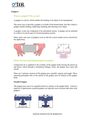
- 1. INDIAN INSTITUTE OF ROBOTICS Grippers What is a gripper? Why use one? A gripper is a device which enables the holding of an object to be manipulated. The easier way to describe a gripper is to think of the human hand. Just like a hand, a gripper enables holding, tightening, handling and releasing of an object. A gripper is just one component of an automated system. A gripper can be attached to a robot or it can be part of a fixed automation system. Many styles and sizes of grippers exist so that the correct model can be selected for the application. What is the basic operating principal of a gripper? Compressed air is supplied to the cylinder of the gripper body forcing the piston up and down, which through a mechanical linkage, forces the gripper jaws open and closed. There are 3 primary motions of the gripper jaws; parallel, angular and toggle. These operating principals refer to the motion of the gripper jaws in relation to the gripper body. Parallel Gripper The gripper jaws move in a parallel motion in relation to the gripper body. Used in a majority of applications, parallel grippers are typically more accurate than other style grippers.
- 2. INDIAN INSTITUTE OF ROBOTICS Angular Gripper The gripper jaws are opened and closed around a central pivot point, moving in a sweeping or arcing motion. Angular grippers are often used when limited space is available or when the jaws need to move up and out of the way. Toggle Gripper The pivot point jaw movement acts as an over-center toggle lock, providing a high grip force to weight ratio. This mechanism will remain locked even if air pressure is lost. Differences between a 2-Jaw and 3-Jaw gripper 2-Jaw Gripper: The most popular style of gripper, all 2 Jaw grippers (angular, parallel and toggle) provide 2 mounting locations for the fingers that come in contact with the part to be grasped. The jaws move in a synchronous motion opening and closing toward the central axis of the gripper body 3-Jaw Gripper: A more specialized style of gripper, all 3 Jaw grippers (parallel and toggle) provide 3 mounting locations for the fingers that come in contact with the part to be grasped. The jaws move in a synchronous motion opening and closing toward the central axis of the gripper body. 3 Jaws provide more contact with the part to be grasped and more accurate centering than 2 jaw models.
- 3. INDIAN INSTITUTE OF ROBOTICS Internal vs External Gripping Grippers are used in two different holding options, External and Internal. The option used is determined by the geometry of the part to be grasped, the process to be performed, orientation of the parts to be grasped and the physical space available. External: External gripping is the most common way to hold parts. The closing force of the gripper is used to hold the part. Internal: Internal gripping is used when the part geometry will allow and when the process to be performed need access to the outside surface of the part grasped. The opening force of the gripper is used to hold the part. Tooling/Finger design considerations Custom gripper tooling/fingers are needed for each application. Fingers are used to actually make contact with the part to be grasped. Careful consideration when designing these fingers can greatly reduced the size and grip force of the gripper needed for the application. The encompassing or retention finger shape is preferred because it increases stability and also reduces the necessary grip force. However, the additional jaw travel required to encompass or retain the part must be taken into consideration.
- 4. INDIAN INSTITUTE OF ROBOTICS Rotary Actuators What is a rotary actuator? What does it do? The rotary actuator is a device use to alternate the rotated position of an object. Just like the human wrist the actuator enables the rotation of an object, except that rotary actuators are available in a wide variety of models with different — Sizes, Torques, Rotation angles. The energy for the rotation is delivered by pneumatic pressure. The rotary actuator converts the air pressure from a linear motion to a rotating motion. What is the basic operating principal of a Rotary Actuator? The rotary actuator converts the air pressure from a linear motion to a rotating motion. This is done by a rack and pinion. Air pressure is supplied pushing the piston in a linear motion, attached to the piston is a straight set of gear teeth called a "rack". The rack is pushed in a linear motion as the piston moves. The gear teeth of the rack are meshed with the circular gear teeth of a "pinion" forcing the pinion to rotate. The pinion can be rotated back into the original position by supplying air pressure to the opposite side of the air cylinder pushing the rack back in the other direction. The pinion is connected to a shaft that protrudes from the body of the rotary actuator. This shaft can be connected to various tools or grippers.