1. with the AgGPS® TrueGuide™ System Quick Reference Card
CONNECTING THE SYSTEM
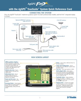
Once the AgGPS® TrueGuide™ implement guidance system has been professionally installed, add the FmX™ integrated display
as shown:
Optional LMR400 65’ extension L1/L2 GPS antenna
cable (P/N 67473)
Coaxial cable
(P/N 68295)
L1/L2
GPS antenna Coaxial cable
FmX integrated
(P/N 67472)
display
Antenna
FmX to NavController II
cable with port replicator
(P/N 75741)
Right-angle cable NavController II
(P/N 50499)
FmX power cable
Power adaptor cable
(P/N 67095)
Basic power cable
(P/N 67258) Main power bus cable
(P/N 67259)
Run Screen layout
Offline guidance display –
When the vehicle is online, the Home – Use to close a field and return to
center indicators are green. When the start window.
the vehicle moves offline, the Setup and Configuration – Tap to
indicators change to red and move change setup and calibration options when
to either side, depending on the the field is open.
direction to the line.
Run icon – Tap to get started in a field.
Vehicle view icon – Tap to
toggle between overhead and Active plug-in tabs – Show status
trailing views. and control functions for the applications
connected to the FmX integrated display
Information icon – Tap to (in this example, TrueGuide). Tap the Tab
display a larger amount of icon to change the tab.
permanent text for operations
relating to the display. TrueGuide status – Status indicates
whether the system is “Waiting” or “On”.
Zoom and Pan icons – Tap Tap Auto (On) button to turn the system
to show zoom and pan function on; tap Off to turn it off
buttons.
Engage panel – Contains the engage
Coverage theme – Panel displays controls for plug-ins such as Autopilot™,
the coverage and variety tracking
settings. You can view height, TrueTracker™ implement steering, and
coverage/overlap, variety, and GPS FieldLevel II automated leveling system.
quality. You can also control for coverage
logging.
1
2. configuring and using the trueguide system
Before starting the configuration, make sure that the Tap Tips for more information on the dimensions
Autopilot automated steering system is installed, and that required for each tab:
both the Autopilot plugin and the TrueGuide plugin are
activated on the FmX integrated display.
Setting up the implement
1. In the Configuration Selection screen, tap Switch to
change to another implement or tap Edit to edit the
current implment:
4. Define the guidance and implement dimensions. Enter
required TrueGuide implement and GPS antenna
measurements in the Geometry tab:
2. In the Configuration screen, tap the required implement
and then tap Setup:
Note: You can update existing (saved) implements with
implement geometry to support the TrueGuide system.
Note: Antenna offsets are provided when the antenna cannot
be placed directly over the working point of the implement.
These offsets should be minimized whenever possible.
Settings on the Geometry tab are required for
3. In turn, enter the required information in the Operations, implement modeling. The antenna offsets are required
Guidance, Geometry, Overlap, and Extras tabs. when using the TrueGuide system:
Tip Usage
D. Hitch to Ground Measured from the tractor hitch pin to the soil
Contact Point engagement point that the implement rotates
about.
E. Antenna Front/ Measured from the implement working point to
Back offset the center of the GPS antenna (if mounted).
F. Antenna Left/ The offset is measured from the center of the
Right Offset and implement to the center of the GPS antenna (if
Antenna Height mounted); the height is the working height of the
GPS antenna.
2
3. 5. Once the dimensions have been entered, tap OK. The Edit Calibrating the TrueGuide system
Implement screen appears.
1. Open a field, set a straight A–B line for calibration in
6. Tap OK. the Run screen and then tap the configuration icon to
return to the Configuration screen without closing the
Setting up the TrueGuide system field:
1. The TrueGuide system requires that the Autopilot system is
installed on the tractor and selected as an active plugin.
Select the TrueGuide plugin and then tap Setup:
2. Select the TrueGuide plugin and then tap Calibrate:
2. Configure the default settings for the TrueGuide system,
including the fixed axle to hitch distance:
3. The TrueGuide Calibration screen appears. Follow the
on-screen instructions to calibrate the system:
Term Usage
Roll compensation On: Applies roll corrections from tractor.
Off: Applies no roll corrections.
CurveGuide Off: System does not anticipate curves.
TrueGuide only: Allows system to anticipate curves
in order to make corrections for TrueGuide only.
Always On: Keeps CurveGuide on at all times.
TrueGuide Sets the default aggressiveness. See the
Aggressiveness recommended setting for application types.
The recommended aggressiveness is 100%.
Rear Axle to Hitch Enter the distance between the fixed axle of the
Point tractor or center of rotation for tracked vehicles
and the draw bar.
3
4. Enabling the TrueGuide system 4. To disable the TrueGuide system, tap OFF.
1. In the Run screen, with the TrueGuide tab showing, press Note: If you disable the TrueGuide system, the Autopilot system
the AUTO button to enable the TrueGuide system. The provides all guidance:
AUTO button changes to ON when the system is engaged
and the status is WAITING:
TrueGuide status indicators
The status of TrueGuide is indicated on the TrueGuide tab
2. Tap the Engage button to start guidance. Autopilot between the OFF / AUTO (On) buttons:
acquires the line before transitioning to TrueGuide:
TrueGuide Description
status
OFF The system is off.
Disengaged The TrueGuide system is ready but not engaged.
Waiting The Autopilot system is engaged and the TrueGuide
system is preparing to engage after a short pause.
ON The system has engaged and the TrueGuide system is on.
Engaging the systems
To engage the AgGPS Autopilot and TrueGuide systems using
The status is WAITING while Autopilot acquires the line the FmX integrated display, you must have a guidance line
and then changes to ON once TrueGuide takes control: defined and the vehicle must be within the engage limits of
the system.
Do one of the following:
• Tap the Engage button on the main guidance screen.
• Press the optional remote engage foot pedal or rocker
switch.
3. To force TrueGuide on at any time the status is WAITING,
tap ON again.
4
5. Disengaging the system Adjusting the aggressiveness setting
To manually disengage the system, do one of the following: Select the TrueGuide plugin tab on the Run screen:
• Tap the Engage button on the main guidance screen.
• Tap the Engage button on the optional remote control.
• Turn the steering wheel.
The system automatically disengages when:
• The vehicle or implement is outside the engage limits.
• GPS positions are lost on either the implement or the
vehicle.
• The Minimum Fix Quality is not maintained and the
system receives low accuracy positions (for example, no
corrections).
Engage status indicators • Tap the + button to increase the aggressiveness.
• Tap the - button to decrease the aggressiveness.
Engage status Engage button color Vehicle icon color
Ready to engage Viewing GPS status
• General GPS and DGPS status is displayed in the upper
Engaged
right section of the screen; Autopilot receiver status is
Cannot engage located in the upper field and TrueGuide in the lower:
TrueGuide aggressiveness settings
Set the default aggressiveness in the TrueGuide set-up screen.
The table shows recommended values.
• Increasing aggressiveness increases the response to move
the implement back to the guidance line.
• Decreasing aggressiveness smooths the response to the
implement moving offline.
For ... Use as default ...
Steep slopes (10% – 30% 150% • To view more details about the GPS status, tap
Slow-speed applications (2–4 MPH) 125%
the satellite icon to display a summary window:
Normal operation 100%
High-speed applications (>8 MPH) 33%
5