Arduino Severino Serial Board TPS-00759 www.onlineTPS.com
•
0 likes•955 views

Arduino Severino Serial Board TPS-00759 www.onlineTPS.com

Recommended
More Related Content
What's hot
What's hot (19)
Viewers also liked
Similar to Arduino Severino Serial Board TPS-00759 www.onlineTPS.com
Similar to Arduino Severino Serial Board TPS-00759 www.onlineTPS.com (20)
Recently uploaded
Recently uploaded (20)
Arduino Severino Serial Board TPS-00759 www.onlineTPS.com
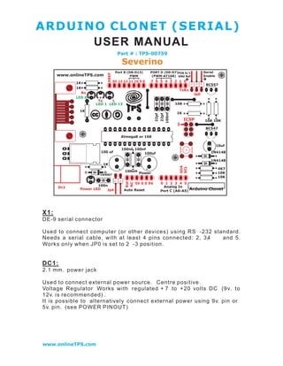
- 1. ARDUINO CLO NET (SERIA L) USER MANUAL Part # : TPS-00759 Severino Port B (D8-D13) PORT D (D0-D7)PIN 0/1 Serial AREF www.onlineTPS.com PWM (PWM-AT168) GNd Ref Enable 0V 13 12 11 10 9 8 7 6 5 4 3 2 1 0 1K BC557 1K TxRx Rx Jp0 LED 0 Tx L LED 1 LED 13 10K 1K 1K 100nf 22pf 22pf ICSP 10K 10K 1 BC547 Atmega8 or 168 10uf 100nf 100nf 100 uf 100uf 1N4148 1N4148 1K SDA SCL 4K7 100uH 10K 1N4007 Power 10K Rst NC 5V 0 0 9V 0 1 2 3 4 5 100n Analog In Dc1 Power LED Jp4 Auto Reset Port C (A0-A5) Arduino Clonet X1: DE-9 serial connector Used to connect computer (or other devices) using RS -232 standard. Needs a serial cable, with at least 4 pins connected: 2, 3, 4 and 5. Works only when JP0 is set to 2 -3 position. DC1: 2.1 mm. power jack Used to connect external power source. Centre positive . Voltage Regulator Works with regulated + 7 to + 20 volts DC (9v. to 12v. is recommended) . It is possible to alternatively connect external power using 9v. pin or 5v. pin. (see POWER PINOUT) www.onlineTPS.com
- 2. ICSP: 2x3 pin header Used to program Atmega with bootloader. The number 1 on both s ides of the board indicates cable pin1 position. Used to upload sketches on Atmega ICs without bootload er (available only in Arduino IDE versions 0011 and 0012). JP0 3 pins jumper When in position 2 -3, this jumper enables serial connection (through X1 connector) to/from computer/devices. Use this as default position. When in position 1 -2, it disables se rial communication, and enables external pull -down resistors on pin0 (RX) and pin1 (TX). Use this only to prevent noise on RX (that seems incoming data to Atmega), that sometimes makes sketch not starting. When removing this jumper, serial communication s disable d, a nd i pin0 and pin1 work as a normal (flo ating) digital pin. Useful when more digital pins are needed, but only when serial communication is not necessary. External pull - down/pull -up resistor is req uired. JP4 2 pins j umper When in position 1 -2, this jumper enables auto reset feature , useful when uploading a sketch to Arduino, resetting Atmega automatically. It makes unnecessary to press reset button (S1) when uploading sketches. Be sure that computer COM Port speed is set to 19200 bp s otherwise auto reset will not work properly. If removed, disables auto reset feature. Very useful to prev ent undesired Atmega reset when using sketches t hat needs serial communication. Auto reset works with DTR pulse on serial pin4. Sometimes Arduino senses a DTR p ulse when connecting X1 (serial connector) and some softwares sends a DTR pulse when it starts or when it closes , that makes Atmega reset when not desired. www.onlineTPS.com
- 3. S1 Tactile button This button resets Atmega, to restart uploaded sketch or to prepare Arduino to r eceive a sketch through serial connector (when auto reset is not active). LEDS Indicative leds POWER led Turns on when Arduino is powered through DC1, +9v. pin or +5v. pin. RX led Blinks when receiving data from computer/device through serial connectio n. TX led Blinks when sending data to computer/device through serial connection. L led This led is connected to digital pin13 with a cu rrent limiter resistor (that doesn !t affect pin13). Useful to test sketches. It is normal to blink when bootloading too . POWER PINOUT 6 pin header RST pin Makes Atmega reset when connected to GND. Useful for Shield Boards, or to connect external reset. NC pin This pin is not connected in Arduino S3v3. Arduino Diecimila has a 3.3 volts pin in the same position. www.onlineTPS.com
- 4. +9v. pin When Arduino DC1 is powered (with battery or DC adaptor), this pin is used as Vout, with the same voltage supplied on DC1 (see DC1), minus 0,7 volts. The total supplied current depends on external power source capacity When Arduino DC1 is not powered, +9v. pin can be used as Vin, connecting it to a external regulated power source (+ 7 to +20 volts) and connecting 0v . pin to external power source GND. In this c ase, +5v. pin can be used as Vout, supplying +5 volts. +5v. pin When Arduino DC1 is powered (wi th battery or DC adaptor), + 5 v. pin supplies +5 volts as a Vout pin. The total s upplied current de pends on Voltage Regulator (7805 supplies up to 1A). This applies onl y to + 5v. pin: Atmega in/out pins only supplies max. 40mA on each pin. When Arduino DC1i s not powered , this pin can be used as Vin, connecting it to a regulated +5v. and connecting 0v . pin to po wer source GND. In this case, +9v. pin is inactive. 0v. pin (GND) Two 0v. pins between +5v. and +9v. / One 0v. pin beside AREF pin . When Arduino DC1 is powered, 0v. pin supplies 0 volts referen ce (GND) for +5v. pin and + 9v. pin. When DC1 is not powered, and Arduino is powered through +5v. p in or +9v. pin, 0v. pin must be used as GND reference , c onnecting it to the external power source GND . DIGITAL IN/OUT PINOUT 8 pin header (x2) 8 digital inputs/outputs: 0 to 7, corresponding to Port D. Pin0 (RX) and pin1 (TX) can be used as communication pins. Pin3, pin5 and pin6 can be used as PWM pins (Atmega168 only). 6 digital inputs/outputs: 8 to 13, corresp onding to Port B. Pin10 (SS), pin11 (MOSI), pin12 (MISO) and pin13 (SCK) can be used as SPI (Serial Peripheral Interface) . Pin9, pin10 and pin11 can be used as PWM pins (Atmega8 and Atmega168). www.onlineTPS.com
- 5. ANALOG IN PINOUT 6 pin header 6 analog inputs: 0 to 5, co rresponding to Port C. Pin4 (SDA) and pin5 (SCL) can be used with I2C (two -w ire serial bus). The analog input pins can be used as digital pins w ith numbers 14 (analog input 0) to 19 (analog input 5). 1 GND pin see 0v. pin (GND). AREF pin The AREF can be set to AVcc (default), internal 2.56 volts (At mega8), internal 1.1 volts (Atmega168), or external AREF. In case of AVcc or internal AREF, AREF pin can be used to attach na external capacitor to decouple the signal, for better noise performance. In case of external AREF, AREF pin is used to attach the extern al reference voltage. Remember that it is necessary to change de fuses (wiring.c file) , an d re -upload sketch, before connecting external voltage to AREF. www.onlineTPS.com
- 6. ARDUINO CLONET (SERIAL) FEATURES • full compatible with Shield Board • AVcc LP filter to reduce noise level on ADC ; • auto reset feature ; • auto reset enable/disable jumper, to avoid not desired rese ting ; • arduino Diecimila compatible reset pin ; • pin13 onboard led, with current limiter resistor ; • TX and RX onboard leds ; • power led with appropriate current limiter resistor (less 20mA of comsumption); • jumper to disable serial communication and to enable RX external pull down resistor, to avoid "RX floating error#. This feature allows to use digital pin0 and pin1 as a normal pin, when serial communication is not need ed; • all similar components (diodes, transistors, leds, capacitors) has the same board orientation (to makes easier to mount with less mistakes) ; • no wires between pads, more space between wires, larger wires, larger pads (better for etching, soldering and drilling, with no short circuits, soldering bridges or open wires in corrosion) ; • only 3 wire bridges ; • electrolitic capacitor (in serial to TTL circuit) changed to bipolar type (to avoid inverted voltage problem when serial cable is not connected); • All jumpers are right angle type, to allow Shield Boards use . www.onlineTPS.com
- 7. ARDUINO CLO NET (SERIA L) Part # : TPS-00759 Severino