1. In many geologic settings, topo-
graphic variations and discontinuities
in the surface of bedrock can influence
the transport and eventual fate of con-
taminants introduced at or near the
ground surface. Determining the
nature and location of anomalous
bedrock can be an essential compo-
nent of hydrologic characterization.
Preliminary analysis of the hydrologic
characteristics of a site in Olathe,
Kansas, U.S., based primarily on bore-
hole data alone, suggested that a clus-
ter of fractures and/or an unmapped
buried stream channel may influence
fluid movement along the drill-
defined bedrock surface. Accurate
mapping of the bedrock surface at
depths ranging from 6 ft to 23 ft and
identification of potential fracture
zones within bedrock were achieved
at this site by integration of the shear-
wave velocity field, calculated using
the multichannel analysis of surface
waves (MASW) method, with a sur-
gical drilling program.
Surface waves appearing on mul-
tichannel seismic data designed to
image environmental, engineering,
and groundwater targets have tradi-
tionally been viewed as noise.Arecent
development incorporating concepts
fromspectralanalysisofsurfacewaves
(SASW) developed for civil engineer-
ing applications with multitrace seis-
mic reflection methods shows great
potential for detecting and in some
cases delineating anomalous subsur-
face materials. Extending the common
use of surface-wave analysis tech-
niques from estimating 1-D shear-
wave velocities to detection and/or
imaging required a laterally continu-
ous approach to data acquisition and
processing. Integrating the MASW
method with CMP-style data acquisi-
tion permits generation of a laterally
continuous 2-D cross-section of the
shear-wave velocity field. The MASW
method, as used here, requires mini-
mal processing and is relatively insen-
sitive to cultural interference. Mating
MASW with the redundant sampling
approach used in CMP data acquisi-
tionprovidesanoninvasivemethodof
detecting horizontal and/or vertical
variations in near-surface material
properties.
Continuous acquisition of multi-
channel surface-wave data along lin-
ear transects has recently shown great
promise in detecting shallow voids
andtunnels,mappingthebedrocksur-
face, locating remnants of under-
ground mines, and delineating frac-
turesystems.Cross-sectionsgenerated
in this manner contain information
about the horizontal and vertical con-
tinuity of materials as shallow as a few
inches down to depths of more than
300 ft in some settings.
Subsidence-prone areas are likely
targets for this type of imaging. De-
creases in the shear-wave velocity
related to decreases in compaction or
localized increases in shear-wave
velocity likely associated with the ten-
sion dome surrounding subsurface
cavities appear to be key indicators of
either active subsidence or areas sus-
ceptible to roof collapse. In situations
where subsidence is active, a dramatic
drop in shear-wave velocity seems
characteristic of areas where earth
materials have begun subsiding into
voids.Thislow-velocityzoneproduces
a unique signature in the shear-wave
velocity field. Since the shear-wave
velocity of earth materials can change
when the strain on those materials
becomes “large,” it is reasonable to
suggest that load-bearing roof rock
above mines or dissolution voids may
1392 THE LEADING EDGE DECEMBER 1999 DECEMBER 1999 THE LEADING EDGE 0000
Multichannel analysis of
surface waves to map bedrock
RICHARD D. MILLER, JIANGHAI XIA, CHOON B. PARK, and JULIAN M. IVANOV, Kansas Geological Survey,
Lawrence, Kansas, U.S.
Figure 2. Shot gathers of geophones with spikes (a), baseplates (b), or base-
plates with weights (c).
a) b) c)
Figure 3. Dispersion curves (a) extracted from Figure 2 and inverted S-wave
velocities (b) based on the dispersion curves.
a) b)
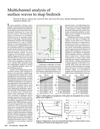
Figure 1. Site map, Olathe,
Kansas, U.S.
2. experience elevated shear-wave veloc-
ities due to loading between pillars, or,
in the case of voids, loading between
supporting sidewalls. The key to
exploiting surface waves as a site
characterization tool resides in their
sensitivity to shear-wave velocity,
compressional-wave velocity, den-
sity, and layering of the half-space.
Several key characteristics of sur-
face waves and surface-wave imaging
make application of this technique
possible in areas and at sites where
other geophysical tools have failed or
provided inadequate or questionable
results. First and probably foremost is
the ease with which surface waves can
be generated. The relative high-ampli-
tude nature of surface waves (in com-
parison to body waves) makes their
application in areas with elevated lev-
els of mechanical/acoustic noise pos-
sible. A half-space is all that is
necessary to propagate surface waves.
Surface-wave propagation does not
require the velocity to increase with
depth and/or a contrast at a bound-
ary (i.e., velocity, density, or combi-
nation [acoustic impedance]).
Conductivity of soils, electrical noise,
conductive structures, and buried
utilities all represent significant chal-
lenges to electrical or EM methods.
These have little or no impact on the
generation or propagation and gener-
ally no influence on the processing or
interpretation of surface-wave data.
This flexibility in acquisition and
insensitivity to environmental noise
allow successful use of shear-wave
velocity profiling in areas where other
geophysical methods are limited.
The Olathe case study discussed
here was designed to target an area
near the southeast corner of a build-
ing used to manufacture electronic
components (Figure 1). Industrial flu-
ids essential to the manufacturing
process were routinely used and
stored in and around this building. If
these fluids were to leak from con-
tainment vessels or plumbing, a
detailed transport and fate model
would be imperative to rapid isola-
tion and extraction of these haz-
ardous fluids. This is a scenario not
unlike thousands currently under
investigation around the country. For
the study described here, two sets of
parallel intersecting profile lines were
located as near the building as prac-
tical and in close proximity to exist-
ing borings. Existing borings and
monitor wells were drilled and com-
pleted to define bedrock and/or to
monitor groundwater. Acquisition
parameters and geometry for MASW
were selected to optimize the imag-
ing of near-surface unconsolidated
materials above bedrock, the bedrock
surface, and several feet into bedrock.
Depths of interest ranged from about
2 ft to 35 ft below the ground surface.
Improving the bedrock surface map
and delineating any potential contam-
inant pathways on or into bedrock
were the primary objective of this
survey.
Data acquisition. Data were acquired
along two pairs of intersecting orthog-
onal lines (Figure 1). Standard CMP
roll-along techniques were used to
record nominal 48-channel shot
records every 4 ft along the entire
0000 THE LEADING EDGE DECEMBER 1999 DECEMBER 1999 THE LEADING EDGE 1393
Figure 4. S-wave velocity contours at the Olathe, Kansas, site, along line (a)
1, (b) 2, (c) 3, and (d) 4.
a)
b)
c)
d)
3. expanse of each line. The asphalt sur-
face covering most of the site necessi-
tated the outfitting of the geophones
with metal baseplates. About half of
line 3 was in a grassy area where tra-
ditional spikes were used to couple
the geophones.A60-channel Geomet-
rics StrataView seismograph recorded
and vertically stacked four impacts of
a 12-lb hammer on a 1 ft2
plate at each
shot station. Single 4.5-Hz Geospace
GS11D geophones spaced 2 ft apart
along the profile lines responded to
frequencies from 8 Hz to 60 Hz (well
within the requirements of this sur-
vey).Source-to-nearest-receiveroffsets
werenominally8ft,makingsource-to-
farthest-receiver offset around 100 ft.
This recording geometry and fre-
quency range provided the optimum
spread and data characteristics for
examining earth materials at this site
between about 3 ft and 50 ft of depth.
Recordingacousticdataonasphalt
or cement surfaces generally comes
with coupling problems, limited
amounts of vertically propagating
body waves, and complex high-fre-
quency trapped and guided waves.
Many studies have shown that
receiver-ground coupling is critical for
high-resolution body-wave surveys.
Maximizing frequency response and
recorded body waves normally
requireslongerspikes,wellseatedinto
competent earth. Coupling experi-
ments at this site suggest that receivers
require only simple ground contact to
record broad-spectrum surface-wave
energy. Little or no improvement is
evident in response (frequency versus
amplitude) when geophones are
“planted” by using spikes, placed on
the ground using plates, or held to the
ground with sandbags (Figure 2). This
observation continues to fuel research
into the use of land streamers, contin-
uous recording techniques, and real-
time data processing.
Data processing. Each 48-trace shot
gather was recorded so all live
receivers were within the optimum
offset window for sampling the sub-
surface materials between 2 ft and 50
ft below ground surface with surface
waves. Multichannel records were
analyzed with SurfSeis (a proprietary
software package of the Kansas
Geological Survey), which facilitates
use of MASW with continuous profil-
ing techniques. Each shot gather gen-
erated one dispersion curve (Figure
3). Care was taken to ensure the spec-
tral properties of the t-x data (shot
gathers) were consistent with the max-
imum and minimum f-vc values (vc is
phase velocities of surface waves) con-
tained in the dispersion curve. Each
dispersion curve was individually
inverted into an x-vs trace. Gathering
all x-vs traces into shot station sequen-
tial order results in a 2-D grid of the
shear-wave velocity field. The shear-
wave velocity field generated in this
fashion does “smear” to a limited
extent velocity anomalies and requires
an understanding of the overall reso-
lution to interpret accurately.
Interpretation. Two-dimensional
cross-sections derived as part of this
study have several striking character-
istics likely influencing the hydrologic
characteristics of this site. Drill data
acquired prior to the seismic survey
helpedoptimizerecordingparameters
and geometries and provided baseline
groundtruthforidentifyingofbedrock
on the shear-wave profiles. The
bedrock surface is characterized by its
high velocity gradient, correlation to
boreholes, and velocity range.
Data quality and characteristics
across line 1 were consistent. Disper-
sive ground roll possessed an opti-
mum bandwidth for investigating
depths from about 4 ft and 30 ft below
ground surface across the entire pro-
file.
Bedrockonthislinewasconfirmed
between 10 ft and 15 ft below ground
surface by drilling. From contoured
shear-wave velocities the surface of
bedrock appears relatively smooth
with a pronounced localized velocity
high in bedrock around station 1065
(Figure 4a). Based on the elevated
shear-wave velocities in this zone, this
anomaly likely signifies an increased
shear modulus, correlating to harder
or less fractured rock. Local outcrop
studies routinely encountered shale
overlaying fractured limestone units
composed of competent blocks that
range from a few feet to hundreds of
feet in horizontal extent separated by
fracture systems. This higher-velocity
zone is likely to be a large block of
limestone bounded by fracture-sepa-
rated smaller blocks. Identification of
individual limestone blocks is pre-
cluded by smearing that is due to the
size of the receiver spread. When we
contrast the southern and northern
halves of this profile, bedrock mater-
ial on the south appears to have the
higher average shear-wave velocity.
This could be related to either changes
inmaterialorfracturingofsubbedrock
materials. The more than 40% drop in
shear-wave velocity of bedrock mate-
rials across this line represents a sig-
nificant change in average “stiffness.”
It is possible that the limestone unit
drill-confirmed to be present beneath
the shale bedrock on the south end
may be missing on the north end, leav-
ing only shale for the first 20 ft or so
below the surface of bedrock on the
north end.
1394 THE LEADING EDGE DECEMBER 1999 DECEMBER 1999 THE LEADING EDGE 0000
Figure 5. Depth-to-bedrock contour map based on (a) drilling alone, (b) seismic data alone, and (c) a combination of
both drilling and seismic data.
a) b) c)
4. There are two features on line 2
with the potential to affect fluid move-
ment along the surface of bedrock
(Figure 4b).An extreme drop in shear-
wave velocity beneath station 2050 is
either a paleochannel infilled with
weathered bedrock material or a frac-
ture/fault zone. On the western flank
of this abrupt low-velocity zone is a
very localized velocity low beneath
station 2040. This feature is pro-
nounced and topographically the low-
est point along this line on the bedrock
surface. Immediately beneath station
2050 a drop in the shear-wave veloc-
ity is evident from the ground surface
to about 5 ft or so. This shallow low-
velocity zone correlates with the
known location of a sewer line buried
along the eastern side of the building.
The second noteworthy feature on this
line is the broad channel feature on
the east end of the line, defined by the
gradual drop in shear-wave velocity
beyond station 2140. This bedrock
channel could be the result of cut-and-
fill, with the infill material having dis-
tinctly different properties than the
low-velocity unconsolidated sedi-
ments above bedrock.
The shear-wave velocity profile of
line 3 is characterized by several geo-
logically significant changes in mate-
rial properties (Figure 4c). These data
correlate quite well with the four bore-
holes in close proximity. This profile
provides insight into the gross texture
and irregular nature of the bedrock
surface. The velocity high at about sta-
tion 3130 may act as a hydrologic bar-
rier, separating fluid introduced south
of station 3140 from any north of sta-
tion 3120. The deepest bedrock
observed on any of the surface-wave
profiles (estimated to be around 25 ft)
is present at the northern end of line 3
near the loading-dock area of the
manufacturing building. Pinnacle-
looking bedrock structures are promi-
nent on the north end of line 3.
Delineating the short-wavelength
undulations (pinnacle features) in the
bedrock surface along the southern
end of this line would not have been
economical with borehole data alone.
We can infer that these localized highs
andlowsinthebedrocksurfacewould
greatly increase the hydrologic com-
plexity of fluids moving along the
bedrock surface. Suggesting that these
severe pinnacle-type features are rep-
resentative of the true bedrock surface
brings up questions of resolution and
accuracy in subsurface sample point
placement. In highly variable areas,
smearing will be more evident and
significant to the accuracy of geologic
models. Some distortion will be pre-
sent in all cases when using this
method to delineate anomalies or to
study changes in material properties.
Two striking features on line 4 are
candidates for breeches in the confin-
ing properties of bedrock (Figure 4d).
The most interesting feature on this
lineislocatedbeneathstation4080and
seems to be directly associated with a
similar feature beneath station 2050 on
line 2. Velocity contrasts associated
with this channel-fault/fracture, its
physicaldimensions,andrelativeloca-
tion are consistent between the two
profiles. A low-velocity zone extend-
ing from very near the surface down
to about 5 ft is the footprint of the
sewer trench seen on line 2 that runs
along the eastern side of the manu-
facturing building. Correlation of the
sewer trench with the extreme veloc-
ity low in the bedrock cannot be
assumed a simple coincidence. There-
fore, a borehole was drilled to confirm
that the lower-velocity channel in
bedrock between stations 4075 and
4088 was real and not an artifact of the
sewer trench and methodology. This
deep channel is probably the most
hydrologically significant feature
related to transport and fate in prox-
imity to the southeast corner of the
building. Consistency in physical
shape and velocity of this feature with
the one interpreted on line 2 is testa-
ment to the consistency in the mea-
surement characteristics for unique
subsurface features. This bedrock low-
velocity zone will influence how fluid
moves along and within shallow
bedrock; it could act either as a barrier
or a conduit.
Bedrock seems to get shallower
toward the eastern end of line 4. This
observation is also consistent with
interpretations of line 2. The anom-
alous feature located beneath station
4140 on line 4 is difficult to correlate
directly to line 2. If this fracture/fault-
channel feature rapidly widens to the
northeast, it would correlate with the
much wider channel-looking feature
on the northeast end of line 2. This fea-
ture may not exist beneath line 2.
Considering the variability commonly
observed in outcrop, abrupt termina-
tionorchangesinfracturesofthismag-
nitude would not be considered
unrealistic. Line 4 possesses several
features that will affect transport and
fate models for this site.
Data resolution is an issue that
must be addressed when using this
technique. It is appropriate to ques-
tion the unlikelihood that bedrock sur-
face on line 3 possesses the extreme
pinnacletopographysuggestedbythis
section.Thegeneraltrendofthesedata
is accurate, as verified by drilling.
Outcrop studies have noted bedrock
blocks scattered beneath weathered
material consistent with the highs
observed on this 4:1 vertically exag-
gerated section. It must be kept in
mind that surface-wave imaging tech-
niques involve the inversion of a wave
that has sampled an area nearly as
wide as deep. As well, the sampling
depth is generally considered to be
half the wavelength. Assuming the
wave is limited to the 2-D plane, the
velocityvalueassignedtoasinglesam-
ple point in the subsurface has been
calculated using a wave that has sam-
pled an area several times the square
of the sample point depth. Therefore,
structures observed on shear-wave
cross-sections are likely smoothed,
subdued, and/or a sculpted version of
what really exists in the subsurface.
Resolution of the drill-defined
bedrock surface map improves signif-
0000 THE LEADING EDGE DECEMBER 1999 DECEMBER 1999 THE LEADING EDGE 1395
Figure 6. This 2.5-D bench representation of lines 1, 2, 3, and 4 allows delin-
eation of bedrock features across this site. Bedrock has been drill-confirmed
to be consistent with the 800 ft/sec contour across this entire site.
5. icantly after incorporation of shear-
wave velocity data (Figure 5). Depth-
to-bedrock contours based on drill
data alone grossly defined the config-
uration of bedrock in proximity to the
boreholes. However, due to the spo-
radic nature and nonuniformity in
drill-hole spacing, drill data alone do
not allow subtle and, in many cases,
extremely significant bedrock features
to be extended, or in some cases even
detected. The bedrock contour map
produced using only shear-wave data
from this site lacks the necessary off-
line control. Incorporating the drill
data and shear-wave data greatly
improved the detail and sitewide res-
olution of the depth-to-bedrock map
as compared to either data set indi-
vidually. Adding a few more seismic
lines could noticeably improve the
3-D aspects of the bedrock contours.
Displayingthedataina2.5-Dfence
diagram allows appraisal of the con-
sistency in measured shear-wave
velocity and helps to interpolate fea-
turesbetweenlines(Figure6).Analysis
of measurement uniqueness for a
given surface location suggests that
bedrock ties are quite good. However,
correlation of shallow features (< 5 ft)
from line to line lacks consistency at
the tie points when spread orientation
is changed. This observation is con-
sistent with the fact that each shear-
wave velocity trace is determined
through simultaneous analysis of all
arrivalswithinthespread.Forthisdata
set each shear-wave velocity value has
beeninfluencedbymaterialalonga94-
ft long spread. The more abrupt and
larger the velocity contrast associated
with a feature, the larger the gradient
on the velocity contours. Subtle
changes and small (one-fourth spread
length) anomalies will be difficult to
confidentlydelineateusingtheMASW
and continuous profiling techniques.
However, abrupt, large gradient
changes in velocity, such as those asso-
ciated with voids or collapse features,
havebeendetectedwithlateraldimen-
sions as small as a few feet.
Summary. High-velocity gradients
within the shear-wave velocity field
consistent with drill-confirmed
bedrock are considered diagnostic of
the bedrock surface and were used to
map the top of bedrock on all four
lines collected at this site. Localized
lateral decreases in the shear-wave
velocity below the bedrock surface
wereclassifiedasfracturezonesorero-
sional channels. Calculating the shear-
wave velocity field from surface-wave
arrivals was accomplished with a high
degree of accuracy regardless of cul-
turalnoise.TheinsensitivityofMASW
to cultural obstacles and noise was
demonstrated at this site (e.g., approx-
imately 220 000 square yards asphalt
parking lot, electrical and mechanical
noise from nearby industrial facilities,
traffic noise from the adjacent high-
way, exploratory drilling on the
asphalt parking lot, and aircraft noise).
Depth-to-bedrock maps produced
using shear-wave velocity and drill
data possesses significantly higher
resolution than maps produced using
drilling or shear-wave velocity data
individually. There is less than 1 ft of
difference in the depth-to-bedrock
interpreted from surface-wave data
compared to the depths determined
through drilling.
Improved resolution on the sur-
face of the bedrock provides insight
intothetextureofbedrockandpermits
identification and appraisal of short-
wavelength variations in the bedrock
surface. The goals and objectives of
this survey were met. Advantages of
mapping the bedrock surface with the
shear-wave velocity field calculated
from surface waves include the insen-
sitivity of MASW to velocity inver-
sions, ease of generating and
propagating surface-wave energy in
comparison to body-wave energy, and
sensitivity to lateral changes in veloc-
ity.
Suggestions for further reading.
“Seismic techniques to delineate disso-
lution features in the upper 1000 ft at a
power plant site,” and “Using MASW to
mapbedrockinOlathe,Kansas,”bothby
Milleretal.,SEG1999ExpandedAbstracts.
“Multichannel analysis of surface waves
using Vibroseis (MASWV)” by Park et
al., SEG 1996 Expanded Abstracts.
“Multichannel analysis of surface
waves,” by Park et al., GEOPHYSICS, v. 64,
n. 3. “Estimation of shear wave velocity
in a compressible Gibson half-space by
inverting Rayleigh wave phase veloc-
ity,” by Xia et al., SEG 1997 Expanded
Abstracts. “Estimation of near-surface
shear-wave velocity by inversion of
Rayleighwave,”byXiaetal.,GEOPHYSICS,
v. 64, n. 3. “Evaluation of the MASW
techniqueinunconsolidatedsediments,”
and “A pitfall in shallow shear-wave
refraction surveying,” both by Xia et al.,
SEG 1999 Expanded Abstracts. LE
Acknowledgments: We appreciate the sup-
portprovidedbyHardingLawsonAssociates
for this applied research project. Technical
assistance by David Laflen, Nathan Geier, as
well as the document preparation work of
Mary Brohammer and Amy Stillwell greatly
contributed to this work.
Corresponding author: R. Miller,
rmiller@kgs.ukans.edu
1396 THE LEADING EDGE DECEMBER 1999 DECEMBER 1999 THE LEADING EDGE 0000
BOOKMARK SEG
SEG search engines
Site search
http://seg.org/search/
Digital Cumulative Index
http://seg.org/search/dci.html
Member search
http://seg.org/search/memsearch.html
http://seg.org/about/
Constitution and Bylaws
http://seg.org/about/constitution.html
Code of Ethics
http://seg.org/about/ethics.html
SEG Foundation Museum
http://seg.org/museum/
Virtual Museum
http://seg.org/museum/VM/
Services
http://seg.org/services/
http://seg.org/business/advertising/
Buyer’s Guide
http://seg.org/business/advertising/
buyersguide
Continuing Education
http://seg.org/services/ce
Consortia information
http://seg.org/consortia/
Employment
http://seg.org/services/employment/
job-list
http://seg.org/services/employment/
resumes
Geophysics meetings and courses
http://seg.org/meetings/seg99/
http://seg.org/meetings/calendar/
http://seg.org/services/ce/disc/
http://seg.org/meetings/
EdgeNET
http://edge-online.org/
GeoArchives
http://seg.org/publications/geoarchive/
Geophysics Online
http://geo-online.org/
Yearbook
http://seg.org/publications/yearbook/
SEG help guide
http://seg.org/about/moreinfo.html
SEG personnel contact information
http://seg.org/about/addresses.html
Send SEG your comments
http://seg.org/services/feedback.html
SEG search engines
Learn more about SEG
Advertise with SEG
Stay current in the field
Attend meetings
Read SEG journals online
Let the SEG help you out

![experience elevated shear-wave veloc-
ities due to loading between pillars, or,
in the case of voids, loading between
supporting sidewalls. The key to
exploiting surface waves as a site
characterization tool resides in their
sensitivity to shear-wave velocity,
compressional-wave velocity, den-
sity, and layering of the half-space.
Several key characteristics of sur-
face waves and surface-wave imaging
make application of this technique
possible in areas and at sites where
other geophysical tools have failed or
provided inadequate or questionable
results. First and probably foremost is
the ease with which surface waves can
be generated. The relative high-ampli-
tude nature of surface waves (in com-
parison to body waves) makes their
application in areas with elevated lev-
els of mechanical/acoustic noise pos-
sible. A half-space is all that is
necessary to propagate surface waves.
Surface-wave propagation does not
require the velocity to increase with
depth and/or a contrast at a bound-
ary (i.e., velocity, density, or combi-
nation [acoustic impedance]).
Conductivity of soils, electrical noise,
conductive structures, and buried
utilities all represent significant chal-
lenges to electrical or EM methods.
These have little or no impact on the
generation or propagation and gener-
ally no influence on the processing or
interpretation of surface-wave data.
This flexibility in acquisition and
insensitivity to environmental noise
allow successful use of shear-wave
velocity profiling in areas where other
geophysical methods are limited.
The Olathe case study discussed
here was designed to target an area
near the southeast corner of a build-
ing used to manufacture electronic
components (Figure 1). Industrial flu-
ids essential to the manufacturing
process were routinely used and
stored in and around this building. If
these fluids were to leak from con-
tainment vessels or plumbing, a
detailed transport and fate model
would be imperative to rapid isola-
tion and extraction of these haz-
ardous fluids. This is a scenario not
unlike thousands currently under
investigation around the country. For
the study described here, two sets of
parallel intersecting profile lines were
located as near the building as prac-
tical and in close proximity to exist-
ing borings. Existing borings and
monitor wells were drilled and com-
pleted to define bedrock and/or to
monitor groundwater. Acquisition
parameters and geometry for MASW
were selected to optimize the imag-
ing of near-surface unconsolidated
materials above bedrock, the bedrock
surface, and several feet into bedrock.
Depths of interest ranged from about
2 ft to 35 ft below the ground surface.
Improving the bedrock surface map
and delineating any potential contam-
inant pathways on or into bedrock
were the primary objective of this
survey.
Data acquisition. Data were acquired
along two pairs of intersecting orthog-
onal lines (Figure 1). Standard CMP
roll-along techniques were used to
record nominal 48-channel shot
records every 4 ft along the entire
0000 THE LEADING EDGE DECEMBER 1999 DECEMBER 1999 THE LEADING EDGE 1393
Figure 4. S-wave velocity contours at the Olathe, Kansas, site, along line (a)
1, (b) 2, (c) 3, and (d) 4.
a)
b)
c)
d)](data:image/gif;base64,R0lGODlhAQABAIAAAAAAAP///yH5BAEAAAAALAAAAAABAAEAAAIBRAA7)