1. 6 Cross-Sectional Properties
of Structural Members
Introduction
Beam design requires the knowledge of material strengths
(allowable stresses), critical shear and moment values, and
information about their cross-section. The shape and pro-
portion of a beam cross-section is critical in keeping bend-
ing and shear stresses within allowable limits and
moderating the amount of deflection that will result from
the loads. Why does a 2– * 8– joist standing on edge de-
flect less when loaded at midspan than the same 2– * 8–
used as a plank? Columns with improperly configured
cross-sections may be highly susceptible to buckling un-
der relatively moderate loads. Are circular pipe columns,
then, better at supporting axial loads than columns with a
cruciform cross-section? (Figure 6.1)
In subsequent chapters, it will be necessary to calculate
two cross-sectional properties crucial to the design of
beams and columns. The two properties are the centroid
and the moment of inertia.
6.1 CENTER OF GRAVITY—CENTROIDS
Center of gravity, or center of mass, refers to masses or
weights and can be thought of as a single point at which
the weight could be held and be in balance in all direc-
tions. If the weight or object were homogeneous, the cen-
ter of gravity and the centroid would coincide. In the case
of a hammer with a wooden handle, its center of gravity
would be close to the heavy steel head, and the centroid,
which is found by ignoring weight and considering only
volume, would be closer to the middle of the handle.
Because of varying densities, the center of gravity and the
centroid do not coincide.
Centroid usually refers to the centers of lines, areas, and
volumes. The centroid of cross-sectional areas (of beams
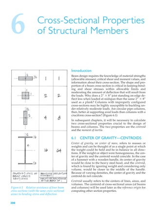
Figure 6.1 Relative resistance of four beam and columns) will be used later as the reference origin for
cross-sections (with the same cross-sectional computing other section properties.
areas) to bending stress and deflection.
300
12. Cross-Sectional Proper ties of Str uctur al Member s 311
6.2 MOMENT OF INERTIA OF AN AREA
The moment of inertia, or second-moment as it is sometimes
called, is a mathematical expression used in the study of
the strength of beams and columns. It measures the effect
of the cross-sectional shape of a beam on the beam’s resis-
tance to bending stress and deflection. Instability or buck-
ling of slender columns is also affected by the moment of
inertia of its cross-section.
The moment of inertia, or I-value, is a shape factor that
quantifies the relative location of material in a cross-section
Area = b * h 1in.2 2
in terms of effectiveness. A beam section with a large mo-
ment of inertia will have smaller stresses and deflections
under a given load than one with a lesser I-value. A long, Perimeter = 2b + 2h 1in.2
slender column will not be as susceptible to buckling later-
ally if the moment of inertia of its cross-section is sufficient. Figure 6.6 Rectangular beam cross-section.
Moment of inertia is a measure of cross-sectional stiffness,
whereas the modulus of elasticity E (studied in Chapter 5)
is a measure of material stiffness.
The concept of moment of inertia is vital to understanding
the behavior of most structures, and it is unfortunate this
concept has no accurate physical analogy or description.
The dimensional unit for moment of inertia I is inches to
the fourth power (in.4).
Assuming the rectangular cross-section shown in Figure 6.6,
a physical description can be given as follows:
area = b * h 1in.2 2
perimeter = 2b + 2h 1in.2
However, the moment of inertia for the cross-section is
bh3 4
I = in.
12
Figure 6.7(a) 2– * 6– joist.
for a rectangular cross-section.
The second moment of an area (area times a distance
squared) is quite abstract and difficult to visualize as a
physical property.
If we consider two prismatic beams made of the same ma-
terial but with different cross-sections, the beam whose
cross-sectional area had the greater moment of inertia
would have the greater resistance to bending. To have a
greater moment of inertia does not necessarily imply,
however, a greater cross-sectional area. Orientation of a
cross-section with respect to its bending axis is crucial in
obtaining a large moment of inertia.
A 2– * 6– rectangular cross-section is used as a joist in
Figure 6.7(a) and as a plank in Figure 6.7(b). From experi-
ence, it is already known that the joist is much more resistant
to bending than the plank. Like many structural elements,
the rectangle has a strong axis (orientation) and a weak axis.
It is far more efficient to load a cross-section so that bending
occurs about its strong axis. Figure 6.7(b) 6– * 2– plank.
13. 312 Chapter 6
It may help to understand the concept of moment of iner-
tia if we draw an analogy based upon real inertia due to
motion and mass. Imagine the two shapes shown in
Figure 6.8 to be cut out of a 1 -inch steel plate and placed
2
and spun about axis x-x. The two shapes have equal areas,
but the one in Figure 6.8(a) has a much higher moment of
inertia Ix-x with respect to the axis of spin. It would be
much harder to start it spinning, and once moving, it
would be much harder to stop. The same principle is in-
Figure 6.8(a) Wide-flange shape. volved when a figure skater spins on ice. With arms held
close in, the skater will rotate rapidly; with arms out-
stretched (creating increased resistance to spin and/or
more inertia), the skater slows down.
In our discussion about the method of finding the center
of gravity for areas, each area was subdivided into small
elemental areas that were multiplied by their respective
perpendicular distances from the reference axis. The pro-
cedure is somewhat similar for determining the moment
of inertia. The moment of inertia about the same axis
would require, however, that each elemental area be
multiplied by the square of the respective perpendicular
distances from the reference axis.
Figure 6.8(b) Cruciform shape. A moment of inertia value can be computed for any shape
with respect to any reference axis (Figure 6.9).
Suppose we wanted to find the moment of inertia of an ir-
regular area, as shown in Figure 6.9, about the x axis. We
would first consider the area to consist of many infinitely
small areas dA (where dA is a much smaller area than ¢A).
Considering the dA shown, its moment of inertia about the
x axis would be y2dA. However, this product is only a
minute portion of the whole moment of inertia. Each dA
making up the area, when multiplied by the square of its
corresponding moment arm y and added together, will
give the moment of inertia of the entire area about the
x axis.
The moment of inertia of an area about a given axis is de-
fined as the sum of the products of all the elemental areas
and the square of their respective distances to that axis.
Therefore, the following two equations from Figure 6.9 are
A
Figure 6.9 Moment of inertia of an irregular
Ix = Ύ
0
y2dA
area. A
Iy = Ύ
0
x2dA
The difficulty of this integration process is largely depen-
dent on the equation of the outline of the area and its lim-
its. When the integration becomes too difficult or a more
16. Cross-Sectional Proper ties of Str uctur al Member s 315
Table 6.2 Moments of inertia for simple geometric shapes.
Shape Moment of Inertia (Ix )
bh3
Ix =
12
bh3
Ix =
36
πr4 πd4
Ix = =
4 64
π1D4 - d4 2
Ix =
64
π
Ix = r4 a b = 0.11r4
8
-
8 9π
17. 316 Chapter 6
6.6 Determine the value of I about the x axis (centroidal).
Solution:
This example will be solved using the negative area method.
Solid Voids
bh3
Isolid =
12
bh3
Iopenings = 2 *
12
16–216–2 3
Isolid = = 108 in.4
12
12–214–2 3
Iopenings = 2 * = 21.3 in.4
12
Ix = 108 in.4 - 21.3 in.4 = 86.7 in.4
Note: Ix is an exact value here, because the computations were
based on an exact equation for rectangles.
18. Cross-Sectional Proper ties of Str uctur al Member s 317
Moment of Inertia by Integration:
Ixc = Ύ y dA
2
where
dA = bdy 1b = base2
y varies from
0 → +2–
0 → –2– }
while b = 2”
and from:
+2– → +3–
–2– → –3– }
while b = 6”
Ixc = Ύ y bdy
A
2
Treat b as a constant within its defined boundary lines.
+2 +3 -2
Ixc = Ύ 122y2dy + Ύ 162y2dy + Ύ 162y2dy
-2 +2 -3
2y3 + 2 6y3 +3 6y3 -2
Ixc = ` + ` + `
3 -2 3 +2 3 -3
= 18 - 3-842 + 2127 - 82 + 21 -8 - 3-2742
2
Ixc
3
Ixc = 10.67 + 38 + 38 = 86.67 in.4
24. Cross-Sectional Proper ties of Str uctur al Member s 323
Problems
Determine Ix and Iy for the cross-sections in Problems 6.6
through 6.8 and Ix for Problems 6.9 through 6.11.
6.6
6.7
6.8
25. 324 Chapter 6
6.9 All members are S4S (surfaced on four sides). See
Table A1 in the Appendix.
2 * 4 S4S; 1.5– * 3.5–; A = 5.25 in.2
2 * 12 S4S; 1.5– * 11.25–; A = 16.88 in.2
6.10
6.11 See the steel tables in the Appendix Table A3.
29. 328 Chapter 6
Problems
Determine the moments of inertia for the composite areas
using the standard rolled sections shown below.
6.12
6.13
6.14
3
A built-up box column is made by welding two 4 – * 16–
plates to the flanges of two C15 × 50. For structural rea-
sons, it is necessary to have Ix equal to Iy. Find the distance
W required to achieve this.
30. Cross-Sectional Proper ties of Str uctur al Member s 329
6.4 RADIUS OF GYRATION
In the study of column behavior, we will be using the term
radius of gyration (r). The radius of gyration expresses the
relationship between the area of a cross-section and a cen-
troidal moment of inertia. It is a shape factor that mea-
sures a column’s resistance to buckling about an axis.
Assume that a W14 × 90 steel column (Figure 6.12) is axi-
ally loaded until it fails in a buckling mode (Figure 6.13).
An examination of the buckled column will reveal that
failure occurs about the y axis. A measure of the column’s
ability to resist buckling is its radius of gyration (r) value.
For the W14 × 90, the radius of gyration values about the x
and y axes are Figure 6.12 Axially loaded wide-flange
column.
W14 * 90: rx = 6.14–
ry = 3.70–
The larger the r value, the more resistance offered against
buckling.
The radius of gyration of a cross-section (area) is defined
as that distance from its moment of inertia axis at which
the entire area could be considered as being concentrated
(like a black hole in space) without changing its moment
of inertia (Figure 6.14).
If
A1 = A2
and
Ix1 = Ix2
then
Ix = Ar 2
Ix
‹ rx2 =
A
and
Ix
rx = Figure 6.13 Column buckling about the weak
CA
(y) axis.
Iy
ry =
DA
For all standard rolled shapes in steel, the radius of gyra- Figure 6.14 Radius of gyration for A1 and A2.
tion values are given in the steel section properties table in
the Appendix (Tables A3 through A6).
31. 330 Chapter 6
Example Problems: Radius of Gyration
6.12 Using the cross-section shown in Example Problem
6.11, we found that
Ix = 1,305 in.4; A = 26.5 in.2
Iy = 389 in.4
The radii of gyration for the two centroidal axes are
computed as
Ix 1,305 in.4
rx = = = 7.02–
AA D 26.5 in.2
Iy 389 in.4
ry = = = 3.83–
DA D 26.5 in.2
6.13 Two identical square cross-sections are oriented as
shown in Figure 6.15. Which of these has the larger I
value? Find the radius of gyration r for each.
Solution:
bh3 a1a2 3 a4
Figure (a): Ix = = =
12 12 12
Figure (b): Made up of four triangles
41bh3 2
‹ Ix = + 41Ady2 2
36
h 0.707a
b = 0.707a; h = 0.707a; dy = =
Figure 6.15(a) Square cross-section (a)x(a). 3 3
410.707a * 30.707a43 2 0.707a 2
+ 4a * 0.707a * 0.707a b a b
1
Ix =
36 2 3
a4 a4 3a4 a4
Ix = + = =
36 18 36 12
Both cross-sections have equal radii of gyration.
a4
Ix a2
12 a 1 a
rx = = = = =
AA Sa2 C 12 2A 3 213
Figure 6.15(b) Square cross-section rotated 45°.