SlideShare a Scribd company logo
1 of 29
Download to read offline
Lecturer;
Dr. Dawood S. Atrushi
Dec. 2014 – Jan. 2015
Bending- and Shearing
Stresses
- y1
2
)
of the beam
Shear Stress in Beam of
Rectangular Cross Section
¢  For a beam subjected to M and V with
rectangular cross section having width
b and height h, the shear stress τ
acts parallel to shear force V.
January, 2015Bending Stresses - DAT2
ular Cross Section
d V with rectangular cross section
e shear stress acts parallel to the
the width of the beam
the a
small
act
lly as
subjected the a
solate a small
stresses act
d horizontally as
urfaces are free,
be vanish, i.e.
2
tion subjected the a
e isolate a small
ear stresses act
nied horizontally as
om surfaces are free,
must be vanish, i.e.
h/2
The top and bottom surfaces are free,
then the shear stress τmust be vanish,
i.e.;
January, 2015Bending Stresses - DAT3
shown
the top and bottom surfaces are fre
then the shear stress must be vanish, i.
= 0 at y = h/2
for two equal rectangular beams o
height h subjected to a concentrate
load P, if no friction between the beam
each beam will be in compression above i
N.A., the lower longitudinal line of th
upper beam will slide w.r.t. the upper lin
mall
act
as
ee,
i.e.
of
ted
ms,
its
the
and bottom surfaces are free,
stress must be vanish, i.e.
y = h/2
qual rectangular beams of
ubjected to a concentrated
o friction between the beams,
be in compression above its
er longitudinal line of the
ll slide w.r.t. the upper line
am
beam of height 2h, shear stress must exist along N.A. to
¢  Consider a small
section of the beam
subjected M and V
in left face and M
+dM and V+dV in
right face.
¢  For the element
mm1p1p, τ acts on
p1p and no stress on
mm1.
January, 2015Bending Stresses - DAT4
onsider a small section of the beam
ected M and V in left face and
dM and V + dV in right face
or the element mm1p1p, acts on
and no stress on mm1
the beam is subjected to pure bending
= constant), x acting on mp and
must be equal, then = 0 on
or nonuniform bending, M acts on mn and M + dM acts on
, consider dA at the distance y form N.A., then on mn
small section of the beam
and V in left face and
V + dV in right face
ment mm1p1p, acts on
ess on mm1
s subjected to pure bending
x acting on mp and
equal, then = 0 on
¢  For non-uniform
bending, M acts on
mn and M + dM acts
on m1n1, consider dA
at the distance y
form N.A., then on
mn
January, 2015Bending Stresses - DAT5
orm bending, M acts on mn and M + dM acts
dA at the distance y form N.A., then on mn
M y
= CC dA
I
tal horizontal force on mp is
M y
CC dA
I
(M + dM) y
p1p and no stress on mm1
if the beam is subjected to pure bending
(M = constant), x acting on mp and
m1p1 must be equal, then = 0 on
pp1
for nonuniform bending, M acts on mn and M +
m1n1, consider dA at the distance y form N.A., then o
M y
x dA = CC dA
I
hence the total horizontal force on mp is
nonuniform bending, M acts on mn and M + dM acts o
consider dA at the distance y form N.A., then on mn
M y
x dA = CC dA
I
nce the total horizontal force on mp is
M y
F1 = CC dA
I
milarly
(M + dM) y
F2 = CCCCC dA
I
Hence the total horizontal force on mp
is;
January, 2015Bending Stresses - DAT6
x dA = CC dA
I
hence the total horizontal force on mp is
M y
F1 = CC dA
I
similarly
(M + dM) y
F2 = CCCCC dA
I
and the horizontal force on pp1 is
F3 = b dx
equation of equilibrium
x dA = CC dA
I
hence the total horizontal force on mp is
M y
F1 = CC dA
I
similarly
(M + dM) y
F2 = CCCCC dA
I
and the horizontal force on pp1 is
F3 = b dx
equation of equilibrium
21
M y
F1 = CC dA
I
similarly
(M + dM) y
F2 = CCCCC dA
I
and the horizontal force on pp1 is
F3 = b dx
equation of equilibrium
F3 = F2 - F1
Similarly
hence the total horizontal force on mp is
M y
F1 = CC dA
I
similarly
(M + dM) y
F2 = CCCCC dA
I
and the horizontal force on pp1 is
F3 = b dx
equation of equilibrium
And the horizontal force on pp1 is;
Equation of equilibrium;
January, 2015Bending Stresses - DAT7
21
F3 = b dx
equation of equilibrium
F3 = F2 - F1
(M + dM) y M y
b dx = CCCCC dA - CC dA
I I
dM 1 V
= CC C y dA = CC y dA
dx Ib I b
denote Q = y dA is the first moment of the cross s
above the level y (area mm1p1p) at which the shear stress act
V Q
= CC shear stress formula
I b
(M + dM) y M y
b dx = CCCCC dA - CC dA
I I
dM 1 V
= CC C y dA = CC y dA
dx Ib I b
denote Q = y dA is the first moment of the cro
above the level y (area mm1p1p) at which the shear stress
V Q
= CC shear stress formula
I b
Denote Q = ∫y dA is the first moment of
the cross section area above the level y
(area mm1p1p) at which the shear stress
τ, then;
Then, the shear stress formula will be;
January, 2015Bending Stresses - DAT8
denote Q = y dA is the first moment of
above the level y (area mm1p1p) at which the shear stre
V Q
= CC shear stress formula
I b
for V, I, b are constants, ~ Q
for a rectangular cross section
h h/2 - y1 b h2
Q = b (C - y1) (y1 + CCC) = C (C
2 2 2 4
V h2
then = CC (C - y1
2
)
2 I 4
For V, I, b are constants,
τ ~ Q for a rectangular
cross section
dx Ib I b
enote Q = y dA is the first moment of the cross section
e the level y (area mm1p1p) at which the shear stress acts, then
V Q
= CC shear stress formula
I b
or V, I, b are constants, ~ Q
or a rectangular cross section
h h/2 - y1 b h2
Q = b (C - y1) (y1 + CCC) = C (C - y1
2
)
2 2 2 4
V h2
2
dM 1 V
= CC C y dA = CC y dA
dx Ib I b
denote Q = y dA is the first moment of the cross section
above the level y (area mm1p1p) at which the shear stress acts, then
V Q
= CC shear stress formula
I b
for V, I, b are constants, ~ Q
for a rectangular cross section
h h/2 - y1 b h2
Q = b (C - y1) (y1 + CCC) = C (C - y1
2
)
2 2 2 4
V h2
then = CC (C - y1
2
)
Then;
January, 2015Bending Stresses - DAT9
1
Q = b (C - y1) (y1 + CCC) = C (C - y1
2
)
2 2 2 4
V h2
then = CC (C - y1
2
)
2 I 4
= 0 at y1 = h/2, max occurs
at y1 = 0 (N.A.)
V h2
V h2
3 V 3
max = CC = CCCC = CC = C ave
8 I 8 b h3
/12 2 A 2
max is 50% larger than ave
V = resultant of shear stress, V and in th
direction
Q = b (C - y1) (y1 + CCC) = C (C
2 2 2 4
V h2
then = CC (C - y1
2
)
2 I 4
= 0 at y1 = h/2, max occurs
at y1 = 0 (N.A.)
V h2
V h2
3 V
max = CC = CCCC = CC =
8 I 8 b h3
/12 2 A
max is 50% larger than ave
V = resultant of shear stress, V
direction
h/2 - y1 b h2
y1) (y1 + CCC) = C (C - y1
2
)
2 2 4
h2
C (C - y1
2
)
I 4
= h/2, max occurs
A.)
V h2
3 V 3
= CCCC = CC = C ave
8 b h3
/12 2 A 2
ger than ave
nt of shear stress, V and in the same
h h/2 - y1 b h2
Q = b (C - y1) (y1 + CCC) = C (C - y1
2
)
2 2 2 4
V h2
then = CC (C - y1
2
)
2 I 4
= 0 at y1 = h/2, max occurs
at y1 = 0 (N.A.)
V h2
V h2
3 V 3
max = CC = CCCC = CC = C
8 I 8 b h3
/12 2 A 2
max is 50% larger than ave
V = resultant of shear stress, V and
h h/2 - y1 b h2
Q = b (C - y1) (y1 + CCC) = C (C - y1
2
)
2 2 2 4
V h2
= CC (C - y1
2
)
2 I 4
0 at y1 = h/2, max occurs
= 0 (N.A.)
V h2
V h2
3 V 3
max = CC = CCCC = CC = C ave
8 I 8 b h3
/12 2 A 2
is 50% larger than ave
V = resultant of shear stress, V and in the sam
for a rectangular cross section
h h/2 - y1 b h2
Q = b (C - y1) (y1 + CCC) = C (C - y1
2
)
2 2 2 4
V h2
then = CC (C - y1
2
)
2 I 4
= 0 at y1 = h/2, max occurs
at y1 = 0 (N.A.)
V h2
V h2
3 V 3
max = CC = CCCC = CC = C ave
8 I 8 b h3
/12 2 A 2
max is 50% larger than ave
V = resultant of shear stress, V and in the
h h/2 - y1 b h
Q = b (C - y1) (y1 + CCC) = C (C - y1
2
)
2 2 2 4
V h2
then = CC (C - y1
2
)
2 I 4
= 0 at y1 = h/2, max occurs
at y1 = 0 (N.A.)
V h2
V h2
3 V 3
max = CC = CCCC = CC = C
8 I 8 b h3
/12 2 A 2
max is 50% larger than ave
V = resultant of shear stress, V and
Example 1
A metal beam with span L = 1m,
q=28kN/m, b=25mm and h=100mm.
Determine bending and shear stresses
at point C.
January, 2015Bending Stresses - DAT10
23
ear force varies continuously along the beam, the warping of cross
due to shear strains does not substantially affect the longitudinal
y more experimental investigation
it is quite justifiable to use the flexure formula in the case of
rm bending, except the region near the concentrate load acts of
ly change of the cross section (stress concentration)
5-11
al beam with span L = 1 m
8 kN/m b = 25 mm h = 100 mm
Example 1
Solution
¢  The shear force VC
and bending
moment MC at the
section through C
are found;
MC = 2.24 kNm
VC = - 8.4 kN
January, 2015Bending Stresses - DAT11
C and C at point C
force VC and bending
C at the section through C
= 2.24 kN-m
= - 8.4 kN
nt of inertia of the section is
The moment of inertia of the section is;
January, 2015Bending Stresses - DAT12
VC = - 8.4 kN
the moment of inertia of the section is
b h3
1
I = CC = C x 25 x 1003
= 2,083 x 10
12 12
normal stress at C is
M y 2.24 x 10⁶ N-mm x 25 mm
C = - CC = - CCCCCCCCCCC =
I 2,083 x 103
mm4
shear stress at C, calculate QC first
AC = 25 x 25 = 625 mm2
yC = 37.5 mm
QC = AC yC = 23,400 mm3
kN-m
kN
ia of the section is
1
= C x 25 x 1003
= 2,083 x 103
mm4
12
is
2.24 x 10⁶ N-mm x 25 mm
= - CCCCCCCCCCC = - 26.9 MPa
2,083 x 103
mm4
calculate QC first
The normal stress at C is;
VC = - 8.4 kN
the moment of inertia of the section is
b h3
1
I = CC = C x 25 x 1003
= 2,083 x 103
m
12 12
normal stress at C is
M y 2.24 x 10⁶ N-mm x 25 mm
C = - CC = - CCCCCCCCCCC = - 2
I 2,083 x 103
mm4
shear stress at C, calculate QC first
AC = 25 x 25 = 625 mm2
yC = 37.5 mm
MC = 2.24 kN-m
VC = - 8.4 kN
e moment of inertia of the section is
b h3
1
I = CC = C x 25 x 1003
= 2,083 x 103
mm4
12 12
ormal stress at C is
M y 2.24 x 10⁶ N-mm x 25 mm
C = - CC = - CCCCCCCCCCC = - 26.9 MPa
I 2,083 x 103
mm4
hear stress at C, calculate QC first
Shear stress at C, calculate Qc first;
January, 2015Bending Stresses - DAT13
I 2,083 x 103
mm4
shear stress at C, calculate QC first
AC = 25 x 25 = 625 mm2
yC = 37.5 mm
QC = AC yC = 23,400 mm3
VC QC 8,400 x 23,400
C = CCC = CCCCCCC = 3.8 MPa
I b 2,083 x 103
x 25
the stress element at point C is shown
Example 5-12
a wood beam AB supporting two
concentrated loads P
b = 100 mm h = 150 mm
M y 2.24 x 10⁶ N-mm x 25 mm
- CC = - CCCCCCCCCCC = - 26.9 MPa
I 2,083 x 103
mm4
s at C, calculate QC first
25 x 25 = 625 mm2
yC = 37.5 mm
= AC yC = 23,400 mm3
VC QC 8,400 x 23,400
= CCC = CCCCCCC = 3.8 MPa
I b 2,083 x 103
x 25
element at point C is shown
2
beam AB supporting two
loads P
0 mm h = 150 mm
M y 2.24 x 10⁶ N-mm x 25 mm
C = - CC = - CCCCCCCCCCC = - 26.9 MP
I 2,083 x 103
mm4
shear stress at C, calculate QC first
AC = 25 x 25 = 625 mm2
yC = 37.5 mm
QC = AC yC = 23,400 mm3
VC QC 8,400 x 23,400
C = CCC = CCCCCCC = 3.8 MPa
I b 2,083 x 103
x 25
the stress element at point C is shown
Example 5-12
a wood beam AB supporting two
concentrated loads P
b = 100 mm h = 150 mm
M y 2.24 x 10⁶ N-mm x 25 mm
C = - CC = - CCCCCCCCCCC = - 26.9 MP
I 2,083 x 103
mm4
shear stress at C, calculate QC first
AC = 25 x 25 = 625 mm2
yC = 37.5 mm
QC = AC yC = 23,400 mm3
VC QC 8,400 x 23,400
C = CCC = CCCCCCC = 3.8 MPa
I b 2,083 x 103
x 25
the stress element at point C is shown
Example 5-12
a wood beam AB supporting two
concentrated loads P
b = 100 mm h = 150 mm
h3
1
C = C x 25 x 1003
= 2,083 x 103
mm4
2 12
t C is
y 2.24 x 10⁶ N-mm x 25 mm
C = - CCCCCCCCCCC = - 26.9 MPa
2,083 x 103
mm4
C, calculate QC first
25 = 625 mm2
yC = 37.5 mm
AC yC = 23,400 mm3
C QC 8,400 x 23,400
The stress
element at point
C is shown
3.8 MPA
3.8 MPA
26.9 MPA26.9 MPA
Example 2
A wood beam AB supporting two
concentrated loads P. Cross sectional
dimentions; b = 100mm, h = 150mm, a =
0.5 m. Given σallow = 11MPa, τallow = 1.2
Mpa, determine Pmax.
January, 2015Bending Stresses - DAT14
ate QC first
m2
yC = 37.5 mm
3,400 mm3
8,400 x 23,400
CCCCCCC = 3.8 MPa
2,083 x 103
x 25
C is shown
pporting two
50 mm
a = 0.5 m allow = 11 MPa allow = 1.2 MPa
determine Pmax
the maximum shear force and bending moment are
Vmax = P Mmax = P a
the section modulus and area are
b h2
S = CC A = b h
6
Example 2
Solution
The maximum shear force and bending
moment are
Vmax = P Mmax = Pa
January, 2015Bending Stresses - DAT15
The section modulus and are are;
a = 0.5 m allow = 11 MPa al
determine Pmax
the maximum shear force and bending momen
Vmax = P Mmax = P a
the section modulus and area are
b h2
S = CC A = b h
6
maximum normal and shear stresses are
Maximum normal and shear stresses
are;
January, 2015Bending Stresses - DAT16
b h2
S = CC A = b h
6
maximum normal and shear stresses are
Mmax 6 P a 3 Vmax 3 P
max = CC = CC max = CCC = CCC
S b h2
2 A 2 b h
allow b h2
11 x 100 x 1502
Pbending = CCCC = CCCCCCC = 8,250 N = 8.25 kN
6 a 6 x 500
2 allow b h 2 x 1.2 x 100 x 150
Pshear = CCCC = CCCCCCCC = 12,000 N = 12 kN
3 3
Pmax = 8.25 kN
8-9 Shear Stresses in Beam of Circular Cross Section
V Q r4
= CC I = CC for solid section
ce and bending moment are
Mmax = P a
d area are
A = b h
shear stresses are
6 P a 3 Vmax 3 P
= CC max = CCC = CCC
b h2
2 A 2 b h
b h2
11 x 100 x 1502
CC = CCCCCCC = 8,250 N = 8.25 kN
6 x 500
h 2 x 1.2 x 100 x 150
C = CCCCCCCC = 12,000 N = 12 kN
3
Vmax = P Mmax = P a
the section modulus and area are
b h2
S = CC A = b h
6
maximum normal and shear stresses are
Mmax 6 P a 3 Vmax 3 P
max = CC = CC max = CCC = CCC
S b h2
2 A 2 b h
allow b h2
11 x 100 x 1502
Pbending = CCCC = CCCCCCC = 8,250 N = 8.25 kN
6 a 6 x 500
2 allow b h 2 x 1.2 x 100 x 150
Pshear = CCCC = CCCCCCCC = 12,000 N = 12 kN
3 3
Pmax = 8.25 kN
Vmax = P Mmax = P a
the section modulus and area are
b h2
S = CC A = b h
6
maximum normal and shear stresses are
Mmax 6 P a 3 Vmax
max = CC = CC max = CCC =
S b h2
2 A
allow b h2
11 x 100 x 1502
Pbending = CCCC = CCCCCCC = 8,250 N
6 a 6 x 500
2 allow b h 2 x 1.2 x 100 x 150
Pshear = CCCC = CCCCCCCC = 12,000
3 3
Pmax = 8.25 kN
Shear Stresses in Beam of
Circular Cross Section
The shear stress at the neutral axis;
January, 2015Bending Stresses - DAT17
Pmax = 8.25 kN
8-9 Shear Stresses in Beam of Circular Cross Section
V Q r4
= CC I = CC for solid section
I b 4
the shear stress at the neutral axis
r2
4 r 2 r3
Q = A y = (CC) (CC) = CC
2 3 3
hear = CCCC = CCCCCCCC = 12,000 N = 1
3 3
max = 8.25 kN
Stresses in Beam of Circular Cross Section
V Q r4
= CC I = CC for solid section
I b 4
ar stress at the neutral axis
r2
4 r 2 r3
= A y = (CC) (CC) = CC b = 2 r
Pshear = CCCC = CCCCCCCC = 1
3 3
Pmax = 8.25 kN
8-9 Shear Stresses in Beam of Circular Cross Section
V Q r4
= CC I = CC for solid section
I b 4
the shear stress at the neutral axis
r2
4 r 2 r3
Q = A y = (CC) (CC) = CC
2 3 3
25
Q r
C I = CC for solid section
4
at the neutral axis
r2
4 r 2 r3
y = (CC) (CC) = CC b = 2 r
2 3 3
January, 2015Bending Stresses - DAT18
V (2 r3
/ 3) 4 V 4 V
max = CCCCCC = CCC = CC
( r4
/ 4) (2 r) 3 r2
3 A
for a hollow circular cross section
2
I = C (r2
4
- r1
4
) Q = C (r2
3
- r1
3
)
4 3
b = 2 (r2 - r1)
then the maximum shear stress at N.A. is
V Q 4 V r2
2
+ r2r1 + r1
2
max = CC = CC (CCCCCC)
I b 3 A r2
2
+ r1
2
V (2 r3
/ 3) 4 V 4 V 4
CCCCCC = CCC = CC = C ave
( r4
/ 4) (2 r) 3 r2
3 A 3
rcular cross section
4 V 4 V 4
C = CCC = CC = C ave
r) 3 r2
3 A 3
ction
2
Q = C (r2
3
- r1
3
)
3
ss at N.A. is
2 2
For a hollow circular cross section;
January, 2015Bending Stresses - DAT19
for a hollow circular cross section
2
I = C (r2
4
- r1
4
) Q = C (r2
3
- r1
3
)
4 3
b = 2 (r2 - r1)
then the maximum shear stress at N.A. is
V Q 4 V r2
2
+ r2r1 + r1
2
max = CC = CC (CCCCCC)
I b 3 A r2
2
+ r1
2
where A = (r2
2
- r1
2
)
Example 5-13
circular cross section
2
C (r2
4
- r1
4
) Q = C (r2
3
- r1
3
)
4 3
2 (r2 - r1)
mum shear stress at N.A. is
V Q 4 V r2
2
+ r2r1 + r1
2
CC = CC (CCCCCC)
I b 3 A r2
2
+ r1
2
A = (r2
2
- r1
2
)
Then the maximum shear
stress at N.A. is;
then the maximum shear stress at N.A.
V Q 4 V r2
2
+
max = CC = CC (CCC
I b 3 A r2
2
where A = (r2
2
- r1
2
)
Example 5-13
a vertical pole of a circular tube
d2 = 100 mm d1 = 80 mm P = 6,675
(a) determine the max in the pole
(b) for same P and same max, calcula
( r / 4) (2 r) 3 r 3 A
for a hollow circular cross section
2
I = C (r2
4
- r1
4
) Q = C (r2
3
- r1
3
)
4 3
b = 2 (r2 - r1)
then the maximum shear stress at N.A. is
V Q 4 V r2
2
+ r2r1 + r1
2
max = CC = CC (CCCCCC)
I b 3 A r2
2
+ r1
2
where A = (r2
2
- r1
2
)
Example 5-13
V (2 r3
/ 3) 4 V 4 V
max = CCCCCC = CCC = CC
( r4
/ 4) (2 r) 3 r2
3 A
for a hollow circular cross section
2
I = C (r2
4
- r1
4
) Q = C (r2
3
- r1
3
)
4 3
b = 2 (r2 - r1)
then the maximum shear stress at N.A. is
V Q 4 V r2
2
+ r2r1 + r1
2
max = CC = CC (CCCCCC)
I b 3 A r2
2
+ r1
2
where A = (r 2
- r 2
)
Example 3
A vertical pole of a
circular tube d2 =100mm,
d1=80mm, P=6,675 N.
(a) determine the σmax in
the pole
(b) for same P and same
τmax, calculate d0 of a
solid circular pole
January, 2015Bending Stresses - DAT20
A = (r2 - r1 )
le of a circular tube
m d1 = 80 mm P = 6,675 N
e the max in the pole
e P and same max, calculate d0
rcular pole
imum shear stress of a circular
Shear Stress in the Webs
of Beams with Flanges
January, 2015Bending Stresses - DAT21
circular pole has a diameter approximately 5/8 that of
ress in the Webs of Beams with Flanges
am of wide-flange shape
shear force V, shear stress
complicated
he shear force is carried by shear
web
he shear stress at ef, the same
in the case in rectangular beam, i.e.
For a beam of wide-
flange shape subjected
to shear force V, shear
stress is much more
complicated. Most of
the shear force is
carried by shear
stresses in the web
mly distributed across t
valid with b = t
of
vided
the
area
n the
January, 2015Bending Stresses - DAT22
Consider the shear stress at ef, the same
assumption as in the case in rectangular
beam, i.e. τ parallel to y-axis and
uniformly distributed across t.
stresses in the web
consider the shear st
assumption as in the case
// y axis and uniform
V Q
= CC is still
I b
the first moment Q
the shaded area is di
into two parts, i.e.
upper flange and the
is much more complicated
most of the shear force is carried
stresses in the web
consider the shear stress at ef,
assumption as in the case in rectangular
// y axis and uniformly distributed
V Q
= CC is still valid with b
I b
the first moment Q of
the shaded area is divided
subjected to shear force V, shear stress
is much more complicated
most of the shear force is carried by shear
stresses in the web
consider the shear stress at ef, the same
assumption as in the case in rectangular beam, i.e.
// y axis and uniformly distributed across t
V Q
= CC is still valid with b = t
I b
the first moment Q of
mption as in the case in rectangular beam, i.e.
/ y axis and uniformly distributed across t
V Q
= CC is still valid with b = t
I b
he first moment Q of
shaded area is divided
two parts, i.e. the
er flange and the area
ween bc and ef in the January, 2015Bending Stresses - DAT23
Then the first moment of A1 and A2 w.r.t.
N.A. is;
A1 = b (C - C) A2 = t (C - y1)
2 2 2
then the first moment of A1 and A2 w.r.t. N.A. is
h1 h/2 - h1/2 h1/2 - y1
Q = A1 (C + CCCC) + A2 (y1 + CCCC)
2 2 2
b t
= C (h2
- h1
2
) + C (h1
2
- 4 y1
2
)
8 8
V Q V b t
= CC = CC [C (h2
- h1
2
) + C (h1
2
- 4 y1
2
)]
I b 8 I t 8 8
b h3
(b - t) h1
3
1
where I = CC - CCCC = C (b h3
- b h1
3
+ t h1
12 12 12
maximum shear stress in the web occurs at N.A., y1 = 0
2 2 2
then the first moment of A1 and A2 w.r.t. N.A. is
h1 h/2 - h1/2 h1/2 - y1
Q = A1 (C + CCCC) + A2 (y1 + CCCC)
2 2 2
b t
= C (h2
- h1
2
) + C (h1
2
- 4 y1
2
)
8 8
V Q V b t
= CC = CC [C (h2
- h1
2
) + C (h1
2
- 4 y1
2
)]
I b 8 I t 8 8
b h3
(b - t) h1
3
1
where I = CC - CCCC = C (b h3
- b h1
3
+ t h1
12 12 12
maximum shear stress in the web occurs at N.A., y1 = 0
V
then the first moment of A1 and A2 w.r.t. N.A. is
h1 h/2 - h1/2 h1/2 - y1
Q = A1 (C + CCCC) + A2 (y1 + CCCC)
2 2 2
b t
= C (h2
- h1
2
) + C (h1
2
- 4 y1
2
)
8 8
V Q V b t
= CC = CC [C (h2
- h1
2
) + C (h1
2
- 4 y1
2
)]
I b 8 I t 8 8
b h3
(b - t) h1
3
1
where I = CC - CCCC = C (b h3
- b h1
3
+ t h1
3
)
12 12 12
maximum shear stress in the web occurs at N.A., y1 = 0
V 2 2 2
h h1 h1
A1 = b (C - C) A2 = t (C - y1)
2 2 2
he first moment of A1 and A2 w.r.t. N.A. is
h1 h/2 - h1/2 h1/2 - y1
Q = A1 (C + CCCC) + A2 (y1 + CCCC)
2 2 2
b t
= C (h2
- h1
2
) + C (h1
2
- 4 y1
2
)
8 8
V Q V b t
= CC = CC [C (h2
- h1
2
) + C (h1
2
- 4 y1
2
)]
I b 8 I t 8 8
b h3
(b - t) h1
3
1
I = CC - CCCC = C (b h3
- b h1
3
+ t h1
3
)
12 12 12
h1
) A2 = t (C - y1)
2
A1 and A2 w.r.t. N.A. is
/2 - h1/2 h1/2 - y1
CCCC) + A2 (y1 + CCCC)
2 2
t
+ C (h1
2
- 4 y1
2
)
8
b t
C [C (h2
- h1
2
) + C (h1
2
- 4 y1
2
)]
t 8 8
3
January, 2015Bending Stresses - DAT24
¢  Maximum shear stress in the web occurs
at N.A., y1 = 0
I b 8 I t 8 8
b h3
(b - t) h1
3
1
where I = CC - CCCC = C
12 12 12
maximum shear stress in the web occurs at N.A.,
V
max = CC (b h2
- b h1
2
+ t h1
2
)
8 I t
minimum shear stress occurs where the web mee
h1/2
V b
min = CC (h2
- h1
2
)
= CC = CC [C (h2
- h1
2
) + C (h1
2
- 4 y1
2
)]
I b 8 I t 8 8
b h3
(b - t) h1
3
1
where I = CC - CCCC = C (b h3
- b h1
3
+ t h1
3
)
12 12 12
maximum shear stress in the web occurs at N.A., y1 = 0
V
max = CC (b h2
- b h1
2
+ t h1
2
)
8 I t
minimum shear stress occurs where the web meets the flange, y1 =
h1/2
V b
min = CC (h2
- h1
2
)
8 I t
the maximum stress in the web is from 10% to 60% greater than the
I b 8 I t 8 8
b h3
(b - t) h1
3
1
where I = CC - CCCC = C (b h3
12 12 12
maximum shear stress in the web occurs at N.A., y1
V
max = CC (b h2
- b h1
2
+ t h1
2
)
8 I t
minimum shear stress occurs where the web meets th
h1/2
V b
min = CC (h2
- h1
2
)
8 I t
¢  Minimum shear stress occurs where the
web meets the flange, y = ±h1/2;
Where
with b = t
f
d
e
a
e
Shear stress distribution on the web;
January, 2015Bending Stresses - DAT25
January, 2015Bending Stresses - DAT26
¢  The shear force carried by the web
consists two parts, a rectangle of area h1
τmin and a parabolic segment of area
2/3 h1 (τmax - τmin)
28
the maximum stress in the web is from 10% to
minimum stress
the shear force carried by the web consists two pa
h1 min and a parabolic segment of area b h1 ( max
Vweb = h1 min + b h1 ( max - min)
t h1
= CC (2 max + min)
3
Vweb = 90% ~ 98% of total V
for design work, the approximation to calculate
V <= total shear force
¢  For design work, the approximation to
calculate τmax is
t h1
= CC (2 max + min)
3
Vweb = 90% ~ 98% of total V
for design work, the approximation to calculate
V <= total shear force
max = CC
t h1 <= web area
Example 4
January, 2015Bending Stresses - DAT27
a beam of wide-flange shape wit
and h1 = 290 mm, vertical shear forc
determine max, min and total
the moment of inertia of the cros
A beam of wide-flange
shape with b = 165 mm,
t = 7.5mm, h = 320 mm,
and h1 = 290 mm,
vertical shear force
V = 45 kN.
Determine τmax, τmin
and total shear force in
the web.
V
CC = 20.7 MPa
h1
a T-shaped cross section
= 24 mm h = 200 mm
(top of the web) and max
6 x 24 x 12 + 200 x 24 x 100
CCCCCCCCCCC = 75.77 mm
Example 5
A beam having a T-
shaped cross section
b=100mm, t=24mm,
h=200mm,
V = 45kN. Determine
τmin (top of the web)
and τmax.
January, 2015Bending Stresses - DAT28
Thank You
January, 2015Bending Stresses - DAT29

More Related Content

What's hot

CE72.52 - Lecture 3b - Section Behavior - Shear and Torsion
CE72.52 - Lecture 3b - Section Behavior - Shear and TorsionCE72.52 - Lecture 3b - Section Behavior - Shear and Torsion
CE72.52 - Lecture 3b - Section Behavior - Shear and TorsionFawad Najam
 
Simple stresses and strains
Simple stresses and strains Simple stresses and strains
Simple stresses and strains JISHNU V
 
Padeye design calculation
Padeye design calculationPadeye design calculation
Padeye design calculationadiq1901
 
Lec5-Torsion of thin walled beams
Lec5-Torsion of thin walled beamsLec5-Torsion of thin walled beams
Lec5-Torsion of thin walled beamsMahdi Damghani
 
Simpale stress and simple strain
Simpale stress and simple strainSimpale stress and simple strain
Simpale stress and simple strainKeval Patel
 
Structural Mechanics: Shear stress in Beams (1st-Year)
Structural Mechanics: Shear stress in Beams (1st-Year)Structural Mechanics: Shear stress in Beams (1st-Year)
Structural Mechanics: Shear stress in Beams (1st-Year)Alessandro Palmeri
 
Lec5 torsion of thin walled beams
Lec5 torsion of thin walled beamsLec5 torsion of thin walled beams
Lec5 torsion of thin walled beamsMahdi Damghani
 
Shear stresses on beam (MECHANICS OF SOLIDS)
Shear stresses on beam (MECHANICS OF SOLIDS)Shear stresses on beam (MECHANICS OF SOLIDS)
Shear stresses on beam (MECHANICS OF SOLIDS)Er.Navazhushen Patel
 
CE 72.52 Lecture 4 - Ductility of Cross-sections
CE 72.52 Lecture 4 - Ductility of Cross-sectionsCE 72.52 Lecture 4 - Ductility of Cross-sections
CE 72.52 Lecture 4 - Ductility of Cross-sectionsFawad Najam
 
37467305 torsion-design-of-beam
37467305 torsion-design-of-beam37467305 torsion-design-of-beam
37467305 torsion-design-of-beamSopheak Thap
 
11 energy methods- Mechanics of Materials - 4th - Beer
11 energy methods- Mechanics of Materials - 4th - Beer11 energy methods- Mechanics of Materials - 4th - Beer
11 energy methods- Mechanics of Materials - 4th - BeerNhan Tran
 
Lecture 2 principal stress and strain
Lecture 2 principal stress and strainLecture 2 principal stress and strain
Lecture 2 principal stress and strainDeepak Agarwal
 
Wind load calculation
Wind load calculationWind load calculation
Wind load calculationGodfrey James
 
Unsymmetrical bending (2nd year)
Unsymmetrical bending (2nd year)Unsymmetrical bending (2nd year)
Unsymmetrical bending (2nd year)Alessandro Palmeri
 
Lecture 1 stresses and strains
Lecture 1 stresses and strainsLecture 1 stresses and strains
Lecture 1 stresses and strainsDeepak Agarwal
 
Theory of Plates and Shells
Theory of Plates and ShellsTheory of Plates and Shells
Theory of Plates and ShellsDrASSayyad
 
Calulation of deflection and crack width according to is 456 2000
Calulation of deflection and crack width according to is 456 2000Calulation of deflection and crack width according to is 456 2000
Calulation of deflection and crack width according to is 456 2000Vikas Mehta
 
Torsional Stress
Torsional StressTorsional Stress
Torsional Stresslimon1705
 

What's hot (20)

First moment of area
First moment of areaFirst moment of area
First moment of area
 
CE72.52 - Lecture 3b - Section Behavior - Shear and Torsion
CE72.52 - Lecture 3b - Section Behavior - Shear and TorsionCE72.52 - Lecture 3b - Section Behavior - Shear and Torsion
CE72.52 - Lecture 3b - Section Behavior - Shear and Torsion
 
Simple stresses and strains
Simple stresses and strains Simple stresses and strains
Simple stresses and strains
 
Padeye design calculation
Padeye design calculationPadeye design calculation
Padeye design calculation
 
Lec5-Torsion of thin walled beams
Lec5-Torsion of thin walled beamsLec5-Torsion of thin walled beams
Lec5-Torsion of thin walled beams
 
Simpale stress and simple strain
Simpale stress and simple strainSimpale stress and simple strain
Simpale stress and simple strain
 
Structural Mechanics: Shear stress in Beams (1st-Year)
Structural Mechanics: Shear stress in Beams (1st-Year)Structural Mechanics: Shear stress in Beams (1st-Year)
Structural Mechanics: Shear stress in Beams (1st-Year)
 
Lec5 torsion of thin walled beams
Lec5 torsion of thin walled beamsLec5 torsion of thin walled beams
Lec5 torsion of thin walled beams
 
Shear stresses on beam (MECHANICS OF SOLIDS)
Shear stresses on beam (MECHANICS OF SOLIDS)Shear stresses on beam (MECHANICS OF SOLIDS)
Shear stresses on beam (MECHANICS OF SOLIDS)
 
CE 72.52 Lecture 4 - Ductility of Cross-sections
CE 72.52 Lecture 4 - Ductility of Cross-sectionsCE 72.52 Lecture 4 - Ductility of Cross-sections
CE 72.52 Lecture 4 - Ductility of Cross-sections
 
37467305 torsion-design-of-beam
37467305 torsion-design-of-beam37467305 torsion-design-of-beam
37467305 torsion-design-of-beam
 
11 energy methods- Mechanics of Materials - 4th - Beer
11 energy methods- Mechanics of Materials - 4th - Beer11 energy methods- Mechanics of Materials - 4th - Beer
11 energy methods- Mechanics of Materials - 4th - Beer
 
Design notes for seismic design of building accordance to Eurocode 8
Design notes for seismic design of building accordance to Eurocode 8 Design notes for seismic design of building accordance to Eurocode 8
Design notes for seismic design of building accordance to Eurocode 8
 
Lecture 2 principal stress and strain
Lecture 2 principal stress and strainLecture 2 principal stress and strain
Lecture 2 principal stress and strain
 
Wind load calculation
Wind load calculationWind load calculation
Wind load calculation
 
Unsymmetrical bending (2nd year)
Unsymmetrical bending (2nd year)Unsymmetrical bending (2nd year)
Unsymmetrical bending (2nd year)
 
Lecture 1 stresses and strains
Lecture 1 stresses and strainsLecture 1 stresses and strains
Lecture 1 stresses and strains
 
Theory of Plates and Shells
Theory of Plates and ShellsTheory of Plates and Shells
Theory of Plates and Shells
 
Calulation of deflection and crack width according to is 456 2000
Calulation of deflection and crack width according to is 456 2000Calulation of deflection and crack width according to is 456 2000
Calulation of deflection and crack width according to is 456 2000
 
Torsional Stress
Torsional StressTorsional Stress
Torsional Stress
 

Similar to Lesson 06, shearing stresses

3 bending stress-asgn
3 bending stress-asgn3 bending stress-asgn
3 bending stress-asgnKingJyeWong
 
Stress Resultants
Stress Resultants Stress Resultants
Stress Resultants Deepu Rajan
 
4 transvere shear-asgn
4 transvere shear-asgn4 transvere shear-asgn
4 transvere shear-asgnKingJyeWong
 
EE301 Lesson 15 Phasors Complex Numbers and Impedance (2).ppt
EE301 Lesson 15 Phasors Complex Numbers and Impedance (2).pptEE301 Lesson 15 Phasors Complex Numbers and Impedance (2).ppt
EE301 Lesson 15 Phasors Complex Numbers and Impedance (2).pptRyanAnderson41811
 
Lesson 05, bending and shearing stresses
Lesson 05, bending  and shearing stressesLesson 05, bending  and shearing stresses
Lesson 05, bending and shearing stressesMsheer Bargaray
 
Solution to-2nd-semester-soil-mechanics-2015-2016
Solution to-2nd-semester-soil-mechanics-2015-2016Solution to-2nd-semester-soil-mechanics-2015-2016
Solution to-2nd-semester-soil-mechanics-2015-2016chener Qadr
 
Rectangular Tapered Footing ITI 15.12.22 F1.pdf
Rectangular Tapered Footing ITI 15.12.22 F1.pdfRectangular Tapered Footing ITI 15.12.22 F1.pdf
Rectangular Tapered Footing ITI 15.12.22 F1.pdfPrantik Adhar Samanta
 
Mechanics Of Solids- Stress Transformation in 3D
Mechanics Of Solids- Stress Transformation in 3DMechanics Of Solids- Stress Transformation in 3D
Mechanics Of Solids- Stress Transformation in 3DShaheryar Ahmad
 

Similar to Lesson 06, shearing stresses (19)

3 bending stress-asgn
3 bending stress-asgn3 bending stress-asgn
3 bending stress-asgn
 
Stress Resultants
Stress Resultants Stress Resultants
Stress Resultants
 
Lecture 6.pdf
Lecture 6.pdfLecture 6.pdf
Lecture 6.pdf
 
4 transvere shear-asgn
4 transvere shear-asgn4 transvere shear-asgn
4 transvere shear-asgn
 
EE301 Lesson 15 Phasors Complex Numbers and Impedance (2).ppt
EE301 Lesson 15 Phasors Complex Numbers and Impedance (2).pptEE301 Lesson 15 Phasors Complex Numbers and Impedance (2).ppt
EE301 Lesson 15 Phasors Complex Numbers and Impedance (2).ppt
 
Lesson 05, bending and shearing stresses
Lesson 05, bending  and shearing stressesLesson 05, bending  and shearing stresses
Lesson 05, bending and shearing stresses
 
IARE_SOM_II_PPT.pdf
IARE_SOM_II_PPT.pdfIARE_SOM_II_PPT.pdf
IARE_SOM_II_PPT.pdf
 
Bending stress
Bending stressBending stress
Bending stress
 
Mos unit v
Mos unit vMos unit v
Mos unit v
 
Transverse shear stress
Transverse shear stressTransverse shear stress
Transverse shear stress
 
Transverse shear stress
Transverse shear stressTransverse shear stress
Transverse shear stress
 
Solution to-2nd-semester-soil-mechanics-2015-2016
Solution to-2nd-semester-soil-mechanics-2015-2016Solution to-2nd-semester-soil-mechanics-2015-2016
Solution to-2nd-semester-soil-mechanics-2015-2016
 
Types of beam
Types of beamTypes of beam
Types of beam
 
311 C H12
311 C H12311 C H12
311 C H12
 
Rectangular Tapered Footing ITI 15.12.22 F1.pdf
Rectangular Tapered Footing ITI 15.12.22 F1.pdfRectangular Tapered Footing ITI 15.12.22 F1.pdf
Rectangular Tapered Footing ITI 15.12.22 F1.pdf
 
10.01.03.029
10.01.03.02910.01.03.029
10.01.03.029
 
Formula Book.pdf
Formula Book.pdfFormula Book.pdf
Formula Book.pdf
 
mcq.pptx
mcq.pptxmcq.pptx
mcq.pptx
 
Mechanics Of Solids- Stress Transformation in 3D
Mechanics Of Solids- Stress Transformation in 3DMechanics Of Solids- Stress Transformation in 3D
Mechanics Of Solids- Stress Transformation in 3D
 

More from Msheer Bargaray

Lesson 06, shearing stresses (Updated)
Lesson 06, shearing stresses (Updated)Lesson 06, shearing stresses (Updated)
Lesson 06, shearing stresses (Updated)Msheer Bargaray
 
Lesson 05,bending and shearing stresses
Lesson 05,bending and shearing stressesLesson 05,bending and shearing stresses
Lesson 05,bending and shearing stressesMsheer Bargaray
 
Lesson 04, shearing force and bending moment 01
Lesson 04, shearing force and bending moment 01Lesson 04, shearing force and bending moment 01
Lesson 04, shearing force and bending moment 01Msheer Bargaray
 
Lesson 03, simple stress and strain
Lesson 03, simple stress and strainLesson 03, simple stress and strain
Lesson 03, simple stress and strainMsheer Bargaray
 
Simple Stress and Strain
Simple Stress and StrainSimple Stress and Strain
Simple Stress and StrainMsheer Bargaray
 
Introduction to Strength of Materials
Introduction to Strength of MaterialsIntroduction to Strength of Materials
Introduction to Strength of MaterialsMsheer Bargaray
 

More from Msheer Bargaray (10)

Mohr circle
Mohr circleMohr circle
Mohr circle
 
Lesson 07, torsion
Lesson 07, torsionLesson 07, torsion
Lesson 07, torsion
 
Lesson 06, shearing stresses (Updated)
Lesson 06, shearing stresses (Updated)Lesson 06, shearing stresses (Updated)
Lesson 06, shearing stresses (Updated)
 
Bending stress in beams
Bending stress in beamsBending stress in beams
Bending stress in beams
 
Lesson 05,bending and shearing stresses
Lesson 05,bending and shearing stressesLesson 05,bending and shearing stresses
Lesson 05,bending and shearing stresses
 
Lesson 04, shearing force and bending moment 01
Lesson 04, shearing force and bending moment 01Lesson 04, shearing force and bending moment 01
Lesson 04, shearing force and bending moment 01
 
Tutorial 2
Tutorial 2Tutorial 2
Tutorial 2
 
Lesson 03, simple stress and strain
Lesson 03, simple stress and strainLesson 03, simple stress and strain
Lesson 03, simple stress and strain
 
Simple Stress and Strain
Simple Stress and StrainSimple Stress and Strain
Simple Stress and Strain
 
Introduction to Strength of Materials
Introduction to Strength of MaterialsIntroduction to Strength of Materials
Introduction to Strength of Materials
 

Recently uploaded

11. Properties of Liquid Fuels in Energy Engineering.pdf
11. Properties of Liquid Fuels in Energy Engineering.pdf11. Properties of Liquid Fuels in Energy Engineering.pdf
11. Properties of Liquid Fuels in Energy Engineering.pdfHafizMudaserAhmad
 
"Exploring the Essential Functions and Design Considerations of Spillways in ...
"Exploring the Essential Functions and Design Considerations of Spillways in ..."Exploring the Essential Functions and Design Considerations of Spillways in ...
"Exploring the Essential Functions and Design Considerations of Spillways in ...Erbil Polytechnic University
 
Energy Awareness training ppt for manufacturing process.pptx
Energy Awareness training ppt for manufacturing process.pptxEnergy Awareness training ppt for manufacturing process.pptx
Energy Awareness training ppt for manufacturing process.pptxsiddharthjain2303
 
Arduino_CSE ece ppt for working and principal of arduino.ppt
Arduino_CSE ece ppt for working and principal of arduino.pptArduino_CSE ece ppt for working and principal of arduino.ppt
Arduino_CSE ece ppt for working and principal of arduino.pptSAURABHKUMAR892774
 
UNIT III ANALOG ELECTRONICS (BASIC ELECTRONICS)
UNIT III ANALOG ELECTRONICS (BASIC ELECTRONICS)UNIT III ANALOG ELECTRONICS (BASIC ELECTRONICS)
UNIT III ANALOG ELECTRONICS (BASIC ELECTRONICS)Dr SOUNDIRARAJ N
 
Past, Present and Future of Generative AI
Past, Present and Future of Generative AIPast, Present and Future of Generative AI
Past, Present and Future of Generative AIabhishek36461
 
Software and Systems Engineering Standards: Verification and Validation of Sy...
Software and Systems Engineering Standards: Verification and Validation of Sy...Software and Systems Engineering Standards: Verification and Validation of Sy...
Software and Systems Engineering Standards: Verification and Validation of Sy...VICTOR MAESTRE RAMIREZ
 
Input Output Management in Operating System
Input Output Management in Operating SystemInput Output Management in Operating System
Input Output Management in Operating SystemRashmi Bhat
 
TechTAC® CFD Report Summary: A Comparison of Two Types of Tubing Anchor Catchers
TechTAC® CFD Report Summary: A Comparison of Two Types of Tubing Anchor CatchersTechTAC® CFD Report Summary: A Comparison of Two Types of Tubing Anchor Catchers
TechTAC® CFD Report Summary: A Comparison of Two Types of Tubing Anchor Catcherssdickerson1
 
Comparative study of High-rise Building Using ETABS,SAP200 and SAFE., SAFE an...
Comparative study of High-rise Building Using ETABS,SAP200 and SAFE., SAFE an...Comparative study of High-rise Building Using ETABS,SAP200 and SAFE., SAFE an...
Comparative study of High-rise Building Using ETABS,SAP200 and SAFE., SAFE an...Erbil Polytechnic University
 
Instrumentation, measurement and control of bio process parameters ( Temperat...
Instrumentation, measurement and control of bio process parameters ( Temperat...Instrumentation, measurement and control of bio process parameters ( Temperat...
Instrumentation, measurement and control of bio process parameters ( Temperat...121011101441
 
IVE Industry Focused Event - Defence Sector 2024
IVE Industry Focused Event - Defence Sector 2024IVE Industry Focused Event - Defence Sector 2024
IVE Industry Focused Event - Defence Sector 2024Mark Billinghurst
 
Crystal Structure analysis and detailed information pptx
Crystal Structure analysis and detailed information pptxCrystal Structure analysis and detailed information pptx
Crystal Structure analysis and detailed information pptxachiever3003
 
Transport layer issues and challenges - Guide
Transport layer issues and challenges - GuideTransport layer issues and challenges - Guide
Transport layer issues and challenges - GuideGOPINATHS437943
 
welding defects observed during the welding
welding defects observed during the weldingwelding defects observed during the welding
welding defects observed during the weldingMuhammadUzairLiaqat
 
Risk Management in Engineering Construction Project
Risk Management in Engineering Construction ProjectRisk Management in Engineering Construction Project
Risk Management in Engineering Construction ProjectErbil Polytechnic University
 
complete construction, environmental and economics information of biomass com...
complete construction, environmental and economics information of biomass com...complete construction, environmental and economics information of biomass com...
complete construction, environmental and economics information of biomass com...asadnawaz62
 
Internet of things -Arshdeep Bahga .pptx
Internet of things -Arshdeep Bahga .pptxInternet of things -Arshdeep Bahga .pptx
Internet of things -Arshdeep Bahga .pptxVelmuruganTECE
 

Recently uploaded (20)

11. Properties of Liquid Fuels in Energy Engineering.pdf
11. Properties of Liquid Fuels in Energy Engineering.pdf11. Properties of Liquid Fuels in Energy Engineering.pdf
11. Properties of Liquid Fuels in Energy Engineering.pdf
 
"Exploring the Essential Functions and Design Considerations of Spillways in ...
"Exploring the Essential Functions and Design Considerations of Spillways in ..."Exploring the Essential Functions and Design Considerations of Spillways in ...
"Exploring the Essential Functions and Design Considerations of Spillways in ...
 
Energy Awareness training ppt for manufacturing process.pptx
Energy Awareness training ppt for manufacturing process.pptxEnergy Awareness training ppt for manufacturing process.pptx
Energy Awareness training ppt for manufacturing process.pptx
 
Arduino_CSE ece ppt for working and principal of arduino.ppt
Arduino_CSE ece ppt for working and principal of arduino.pptArduino_CSE ece ppt for working and principal of arduino.ppt
Arduino_CSE ece ppt for working and principal of arduino.ppt
 
UNIT III ANALOG ELECTRONICS (BASIC ELECTRONICS)
UNIT III ANALOG ELECTRONICS (BASIC ELECTRONICS)UNIT III ANALOG ELECTRONICS (BASIC ELECTRONICS)
UNIT III ANALOG ELECTRONICS (BASIC ELECTRONICS)
 
Past, Present and Future of Generative AI
Past, Present and Future of Generative AIPast, Present and Future of Generative AI
Past, Present and Future of Generative AI
 
Software and Systems Engineering Standards: Verification and Validation of Sy...
Software and Systems Engineering Standards: Verification and Validation of Sy...Software and Systems Engineering Standards: Verification and Validation of Sy...
Software and Systems Engineering Standards: Verification and Validation of Sy...
 
Input Output Management in Operating System
Input Output Management in Operating SystemInput Output Management in Operating System
Input Output Management in Operating System
 
TechTAC® CFD Report Summary: A Comparison of Two Types of Tubing Anchor Catchers
TechTAC® CFD Report Summary: A Comparison of Two Types of Tubing Anchor CatchersTechTAC® CFD Report Summary: A Comparison of Two Types of Tubing Anchor Catchers
TechTAC® CFD Report Summary: A Comparison of Two Types of Tubing Anchor Catchers
 
Comparative study of High-rise Building Using ETABS,SAP200 and SAFE., SAFE an...
Comparative study of High-rise Building Using ETABS,SAP200 and SAFE., SAFE an...Comparative study of High-rise Building Using ETABS,SAP200 and SAFE., SAFE an...
Comparative study of High-rise Building Using ETABS,SAP200 and SAFE., SAFE an...
 
Instrumentation, measurement and control of bio process parameters ( Temperat...
Instrumentation, measurement and control of bio process parameters ( Temperat...Instrumentation, measurement and control of bio process parameters ( Temperat...
Instrumentation, measurement and control of bio process parameters ( Temperat...
 
IVE Industry Focused Event - Defence Sector 2024
IVE Industry Focused Event - Defence Sector 2024IVE Industry Focused Event - Defence Sector 2024
IVE Industry Focused Event - Defence Sector 2024
 
Crystal Structure analysis and detailed information pptx
Crystal Structure analysis and detailed information pptxCrystal Structure analysis and detailed information pptx
Crystal Structure analysis and detailed information pptx
 
Transport layer issues and challenges - Guide
Transport layer issues and challenges - GuideTransport layer issues and challenges - Guide
Transport layer issues and challenges - Guide
 
welding defects observed during the welding
welding defects observed during the weldingwelding defects observed during the welding
welding defects observed during the welding
 
Risk Management in Engineering Construction Project
Risk Management in Engineering Construction ProjectRisk Management in Engineering Construction Project
Risk Management in Engineering Construction Project
 
Design and analysis of solar grass cutter.pdf
Design and analysis of solar grass cutter.pdfDesign and analysis of solar grass cutter.pdf
Design and analysis of solar grass cutter.pdf
 
complete construction, environmental and economics information of biomass com...
complete construction, environmental and economics information of biomass com...complete construction, environmental and economics information of biomass com...
complete construction, environmental and economics information of biomass com...
 
POWER SYSTEMS-1 Complete notes examples
POWER SYSTEMS-1 Complete notes  examplesPOWER SYSTEMS-1 Complete notes  examples
POWER SYSTEMS-1 Complete notes examples
 
Internet of things -Arshdeep Bahga .pptx
Internet of things -Arshdeep Bahga .pptxInternet of things -Arshdeep Bahga .pptx
Internet of things -Arshdeep Bahga .pptx
 

Lesson 06, shearing stresses

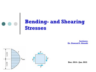
  • 1. Lecturer; Dr. Dawood S. Atrushi Dec. 2014 – Jan. 2015 Bending- and Shearing Stresses - y1 2 ) of the beam
  • 2. Shear Stress in Beam of Rectangular Cross Section ¢  For a beam subjected to M and V with rectangular cross section having width b and height h, the shear stress τ acts parallel to shear force V. January, 2015Bending Stresses - DAT2 ular Cross Section d V with rectangular cross section e shear stress acts parallel to the the width of the beam the a small act lly as subjected the a solate a small stresses act d horizontally as urfaces are free, be vanish, i.e. 2 tion subjected the a e isolate a small ear stresses act nied horizontally as om surfaces are free, must be vanish, i.e. h/2
  • 3. The top and bottom surfaces are free, then the shear stress τmust be vanish, i.e.; January, 2015Bending Stresses - DAT3 shown the top and bottom surfaces are fre then the shear stress must be vanish, i. = 0 at y = h/2 for two equal rectangular beams o height h subjected to a concentrate load P, if no friction between the beam each beam will be in compression above i N.A., the lower longitudinal line of th upper beam will slide w.r.t. the upper lin mall act as ee, i.e. of ted ms, its the and bottom surfaces are free, stress must be vanish, i.e. y = h/2 qual rectangular beams of ubjected to a concentrated o friction between the beams, be in compression above its er longitudinal line of the ll slide w.r.t. the upper line am beam of height 2h, shear stress must exist along N.A. to
  • 4. ¢  Consider a small section of the beam subjected M and V in left face and M +dM and V+dV in right face. ¢  For the element mm1p1p, τ acts on p1p and no stress on mm1. January, 2015Bending Stresses - DAT4 onsider a small section of the beam ected M and V in left face and dM and V + dV in right face or the element mm1p1p, acts on and no stress on mm1 the beam is subjected to pure bending = constant), x acting on mp and must be equal, then = 0 on or nonuniform bending, M acts on mn and M + dM acts on , consider dA at the distance y form N.A., then on mn small section of the beam and V in left face and V + dV in right face ment mm1p1p, acts on ess on mm1 s subjected to pure bending x acting on mp and equal, then = 0 on
  • 5. ¢  For non-uniform bending, M acts on mn and M + dM acts on m1n1, consider dA at the distance y form N.A., then on mn January, 2015Bending Stresses - DAT5 orm bending, M acts on mn and M + dM acts dA at the distance y form N.A., then on mn M y = CC dA I tal horizontal force on mp is M y CC dA I (M + dM) y p1p and no stress on mm1 if the beam is subjected to pure bending (M = constant), x acting on mp and m1p1 must be equal, then = 0 on pp1 for nonuniform bending, M acts on mn and M + m1n1, consider dA at the distance y form N.A., then o M y x dA = CC dA I hence the total horizontal force on mp is nonuniform bending, M acts on mn and M + dM acts o consider dA at the distance y form N.A., then on mn M y x dA = CC dA I nce the total horizontal force on mp is M y F1 = CC dA I milarly (M + dM) y F2 = CCCCC dA I
  • 6. Hence the total horizontal force on mp is; January, 2015Bending Stresses - DAT6 x dA = CC dA I hence the total horizontal force on mp is M y F1 = CC dA I similarly (M + dM) y F2 = CCCCC dA I and the horizontal force on pp1 is F3 = b dx equation of equilibrium x dA = CC dA I hence the total horizontal force on mp is M y F1 = CC dA I similarly (M + dM) y F2 = CCCCC dA I and the horizontal force on pp1 is F3 = b dx equation of equilibrium 21 M y F1 = CC dA I similarly (M + dM) y F2 = CCCCC dA I and the horizontal force on pp1 is F3 = b dx equation of equilibrium F3 = F2 - F1 Similarly hence the total horizontal force on mp is M y F1 = CC dA I similarly (M + dM) y F2 = CCCCC dA I and the horizontal force on pp1 is F3 = b dx equation of equilibrium And the horizontal force on pp1 is;
  • 7. Equation of equilibrium; January, 2015Bending Stresses - DAT7 21 F3 = b dx equation of equilibrium F3 = F2 - F1 (M + dM) y M y b dx = CCCCC dA - CC dA I I dM 1 V = CC C y dA = CC y dA dx Ib I b denote Q = y dA is the first moment of the cross s above the level y (area mm1p1p) at which the shear stress act V Q = CC shear stress formula I b (M + dM) y M y b dx = CCCCC dA - CC dA I I dM 1 V = CC C y dA = CC y dA dx Ib I b denote Q = y dA is the first moment of the cro above the level y (area mm1p1p) at which the shear stress V Q = CC shear stress formula I b Denote Q = ∫y dA is the first moment of the cross section area above the level y (area mm1p1p) at which the shear stress τ, then;
  • 8. Then, the shear stress formula will be; January, 2015Bending Stresses - DAT8 denote Q = y dA is the first moment of above the level y (area mm1p1p) at which the shear stre V Q = CC shear stress formula I b for V, I, b are constants, ~ Q for a rectangular cross section h h/2 - y1 b h2 Q = b (C - y1) (y1 + CCC) = C (C 2 2 2 4 V h2 then = CC (C - y1 2 ) 2 I 4 For V, I, b are constants, τ ~ Q for a rectangular cross section dx Ib I b enote Q = y dA is the first moment of the cross section e the level y (area mm1p1p) at which the shear stress acts, then V Q = CC shear stress formula I b or V, I, b are constants, ~ Q or a rectangular cross section h h/2 - y1 b h2 Q = b (C - y1) (y1 + CCC) = C (C - y1 2 ) 2 2 2 4 V h2 2 dM 1 V = CC C y dA = CC y dA dx Ib I b denote Q = y dA is the first moment of the cross section above the level y (area mm1p1p) at which the shear stress acts, then V Q = CC shear stress formula I b for V, I, b are constants, ~ Q for a rectangular cross section h h/2 - y1 b h2 Q = b (C - y1) (y1 + CCC) = C (C - y1 2 ) 2 2 2 4 V h2 then = CC (C - y1 2 )
  • 9. Then; January, 2015Bending Stresses - DAT9 1 Q = b (C - y1) (y1 + CCC) = C (C - y1 2 ) 2 2 2 4 V h2 then = CC (C - y1 2 ) 2 I 4 = 0 at y1 = h/2, max occurs at y1 = 0 (N.A.) V h2 V h2 3 V 3 max = CC = CCCC = CC = C ave 8 I 8 b h3 /12 2 A 2 max is 50% larger than ave V = resultant of shear stress, V and in th direction Q = b (C - y1) (y1 + CCC) = C (C 2 2 2 4 V h2 then = CC (C - y1 2 ) 2 I 4 = 0 at y1 = h/2, max occurs at y1 = 0 (N.A.) V h2 V h2 3 V max = CC = CCCC = CC = 8 I 8 b h3 /12 2 A max is 50% larger than ave V = resultant of shear stress, V direction h/2 - y1 b h2 y1) (y1 + CCC) = C (C - y1 2 ) 2 2 4 h2 C (C - y1 2 ) I 4 = h/2, max occurs A.) V h2 3 V 3 = CCCC = CC = C ave 8 b h3 /12 2 A 2 ger than ave nt of shear stress, V and in the same h h/2 - y1 b h2 Q = b (C - y1) (y1 + CCC) = C (C - y1 2 ) 2 2 2 4 V h2 then = CC (C - y1 2 ) 2 I 4 = 0 at y1 = h/2, max occurs at y1 = 0 (N.A.) V h2 V h2 3 V 3 max = CC = CCCC = CC = C 8 I 8 b h3 /12 2 A 2 max is 50% larger than ave V = resultant of shear stress, V and h h/2 - y1 b h2 Q = b (C - y1) (y1 + CCC) = C (C - y1 2 ) 2 2 2 4 V h2 = CC (C - y1 2 ) 2 I 4 0 at y1 = h/2, max occurs = 0 (N.A.) V h2 V h2 3 V 3 max = CC = CCCC = CC = C ave 8 I 8 b h3 /12 2 A 2 is 50% larger than ave V = resultant of shear stress, V and in the sam for a rectangular cross section h h/2 - y1 b h2 Q = b (C - y1) (y1 + CCC) = C (C - y1 2 ) 2 2 2 4 V h2 then = CC (C - y1 2 ) 2 I 4 = 0 at y1 = h/2, max occurs at y1 = 0 (N.A.) V h2 V h2 3 V 3 max = CC = CCCC = CC = C ave 8 I 8 b h3 /12 2 A 2 max is 50% larger than ave V = resultant of shear stress, V and in the h h/2 - y1 b h Q = b (C - y1) (y1 + CCC) = C (C - y1 2 ) 2 2 2 4 V h2 then = CC (C - y1 2 ) 2 I 4 = 0 at y1 = h/2, max occurs at y1 = 0 (N.A.) V h2 V h2 3 V 3 max = CC = CCCC = CC = C 8 I 8 b h3 /12 2 A 2 max is 50% larger than ave V = resultant of shear stress, V and
  • 10. Example 1 A metal beam with span L = 1m, q=28kN/m, b=25mm and h=100mm. Determine bending and shear stresses at point C. January, 2015Bending Stresses - DAT10 23 ear force varies continuously along the beam, the warping of cross due to shear strains does not substantially affect the longitudinal y more experimental investigation it is quite justifiable to use the flexure formula in the case of rm bending, except the region near the concentrate load acts of ly change of the cross section (stress concentration) 5-11 al beam with span L = 1 m 8 kN/m b = 25 mm h = 100 mm
  • 11. Example 1 Solution ¢  The shear force VC and bending moment MC at the section through C are found; MC = 2.24 kNm VC = - 8.4 kN January, 2015Bending Stresses - DAT11 C and C at point C force VC and bending C at the section through C = 2.24 kN-m = - 8.4 kN nt of inertia of the section is
  • 12. The moment of inertia of the section is; January, 2015Bending Stresses - DAT12 VC = - 8.4 kN the moment of inertia of the section is b h3 1 I = CC = C x 25 x 1003 = 2,083 x 10 12 12 normal stress at C is M y 2.24 x 10⁶ N-mm x 25 mm C = - CC = - CCCCCCCCCCC = I 2,083 x 103 mm4 shear stress at C, calculate QC first AC = 25 x 25 = 625 mm2 yC = 37.5 mm QC = AC yC = 23,400 mm3 kN-m kN ia of the section is 1 = C x 25 x 1003 = 2,083 x 103 mm4 12 is 2.24 x 10⁶ N-mm x 25 mm = - CCCCCCCCCCC = - 26.9 MPa 2,083 x 103 mm4 calculate QC first The normal stress at C is; VC = - 8.4 kN the moment of inertia of the section is b h3 1 I = CC = C x 25 x 1003 = 2,083 x 103 m 12 12 normal stress at C is M y 2.24 x 10⁶ N-mm x 25 mm C = - CC = - CCCCCCCCCCC = - 2 I 2,083 x 103 mm4 shear stress at C, calculate QC first AC = 25 x 25 = 625 mm2 yC = 37.5 mm MC = 2.24 kN-m VC = - 8.4 kN e moment of inertia of the section is b h3 1 I = CC = C x 25 x 1003 = 2,083 x 103 mm4 12 12 ormal stress at C is M y 2.24 x 10⁶ N-mm x 25 mm C = - CC = - CCCCCCCCCCC = - 26.9 MPa I 2,083 x 103 mm4 hear stress at C, calculate QC first
  • 13. Shear stress at C, calculate Qc first; January, 2015Bending Stresses - DAT13 I 2,083 x 103 mm4 shear stress at C, calculate QC first AC = 25 x 25 = 625 mm2 yC = 37.5 mm QC = AC yC = 23,400 mm3 VC QC 8,400 x 23,400 C = CCC = CCCCCCC = 3.8 MPa I b 2,083 x 103 x 25 the stress element at point C is shown Example 5-12 a wood beam AB supporting two concentrated loads P b = 100 mm h = 150 mm M y 2.24 x 10⁶ N-mm x 25 mm - CC = - CCCCCCCCCCC = - 26.9 MPa I 2,083 x 103 mm4 s at C, calculate QC first 25 x 25 = 625 mm2 yC = 37.5 mm = AC yC = 23,400 mm3 VC QC 8,400 x 23,400 = CCC = CCCCCCC = 3.8 MPa I b 2,083 x 103 x 25 element at point C is shown 2 beam AB supporting two loads P 0 mm h = 150 mm M y 2.24 x 10⁶ N-mm x 25 mm C = - CC = - CCCCCCCCCCC = - 26.9 MP I 2,083 x 103 mm4 shear stress at C, calculate QC first AC = 25 x 25 = 625 mm2 yC = 37.5 mm QC = AC yC = 23,400 mm3 VC QC 8,400 x 23,400 C = CCC = CCCCCCC = 3.8 MPa I b 2,083 x 103 x 25 the stress element at point C is shown Example 5-12 a wood beam AB supporting two concentrated loads P b = 100 mm h = 150 mm M y 2.24 x 10⁶ N-mm x 25 mm C = - CC = - CCCCCCCCCCC = - 26.9 MP I 2,083 x 103 mm4 shear stress at C, calculate QC first AC = 25 x 25 = 625 mm2 yC = 37.5 mm QC = AC yC = 23,400 mm3 VC QC 8,400 x 23,400 C = CCC = CCCCCCC = 3.8 MPa I b 2,083 x 103 x 25 the stress element at point C is shown Example 5-12 a wood beam AB supporting two concentrated loads P b = 100 mm h = 150 mm h3 1 C = C x 25 x 1003 = 2,083 x 103 mm4 2 12 t C is y 2.24 x 10⁶ N-mm x 25 mm C = - CCCCCCCCCCC = - 26.9 MPa 2,083 x 103 mm4 C, calculate QC first 25 = 625 mm2 yC = 37.5 mm AC yC = 23,400 mm3 C QC 8,400 x 23,400 The stress element at point C is shown 3.8 MPA 3.8 MPA 26.9 MPA26.9 MPA
  • 14. Example 2 A wood beam AB supporting two concentrated loads P. Cross sectional dimentions; b = 100mm, h = 150mm, a = 0.5 m. Given σallow = 11MPa, τallow = 1.2 Mpa, determine Pmax. January, 2015Bending Stresses - DAT14 ate QC first m2 yC = 37.5 mm 3,400 mm3 8,400 x 23,400 CCCCCCC = 3.8 MPa 2,083 x 103 x 25 C is shown pporting two 50 mm a = 0.5 m allow = 11 MPa allow = 1.2 MPa determine Pmax the maximum shear force and bending moment are Vmax = P Mmax = P a the section modulus and area are b h2 S = CC A = b h 6
  • 15. Example 2 Solution The maximum shear force and bending moment are Vmax = P Mmax = Pa January, 2015Bending Stresses - DAT15 The section modulus and are are; a = 0.5 m allow = 11 MPa al determine Pmax the maximum shear force and bending momen Vmax = P Mmax = P a the section modulus and area are b h2 S = CC A = b h 6 maximum normal and shear stresses are
  • 16. Maximum normal and shear stresses are; January, 2015Bending Stresses - DAT16 b h2 S = CC A = b h 6 maximum normal and shear stresses are Mmax 6 P a 3 Vmax 3 P max = CC = CC max = CCC = CCC S b h2 2 A 2 b h allow b h2 11 x 100 x 1502 Pbending = CCCC = CCCCCCC = 8,250 N = 8.25 kN 6 a 6 x 500 2 allow b h 2 x 1.2 x 100 x 150 Pshear = CCCC = CCCCCCCC = 12,000 N = 12 kN 3 3 Pmax = 8.25 kN 8-9 Shear Stresses in Beam of Circular Cross Section V Q r4 b h2 S = CC A = b h 6 maximum normal and shear stresses are Mmax 6 P a 3 Vmax 3 P max = CC = CC max = CCC = CCC S b h2 2 A 2 b h allow b h2 11 x 100 x 1502 Pbending = CCCC = CCCCCCC = 8,250 N = 8.25 kN 6 a 6 x 500 2 allow b h 2 x 1.2 x 100 x 150 Pshear = CCCC = CCCCCCCC = 12,000 N = 12 kN 3 3 Pmax = 8.25 kN 8-9 Shear Stresses in Beam of Circular Cross Section V Q r4 = CC I = CC for solid section ce and bending moment are Mmax = P a d area are A = b h shear stresses are 6 P a 3 Vmax 3 P = CC max = CCC = CCC b h2 2 A 2 b h b h2 11 x 100 x 1502 CC = CCCCCCC = 8,250 N = 8.25 kN 6 x 500 h 2 x 1.2 x 100 x 150 C = CCCCCCCC = 12,000 N = 12 kN 3 Vmax = P Mmax = P a the section modulus and area are b h2 S = CC A = b h 6 maximum normal and shear stresses are Mmax 6 P a 3 Vmax 3 P max = CC = CC max = CCC = CCC S b h2 2 A 2 b h allow b h2 11 x 100 x 1502 Pbending = CCCC = CCCCCCC = 8,250 N = 8.25 kN 6 a 6 x 500 2 allow b h 2 x 1.2 x 100 x 150 Pshear = CCCC = CCCCCCCC = 12,000 N = 12 kN 3 3 Pmax = 8.25 kN Vmax = P Mmax = P a the section modulus and area are b h2 S = CC A = b h 6 maximum normal and shear stresses are Mmax 6 P a 3 Vmax max = CC = CC max = CCC = S b h2 2 A allow b h2 11 x 100 x 1502 Pbending = CCCC = CCCCCCC = 8,250 N 6 a 6 x 500 2 allow b h 2 x 1.2 x 100 x 150 Pshear = CCCC = CCCCCCCC = 12,000 3 3 Pmax = 8.25 kN
  • 17. Shear Stresses in Beam of Circular Cross Section The shear stress at the neutral axis; January, 2015Bending Stresses - DAT17 Pmax = 8.25 kN 8-9 Shear Stresses in Beam of Circular Cross Section V Q r4 = CC I = CC for solid section I b 4 the shear stress at the neutral axis r2 4 r 2 r3 Q = A y = (CC) (CC) = CC 2 3 3 hear = CCCC = CCCCCCCC = 12,000 N = 1 3 3 max = 8.25 kN Stresses in Beam of Circular Cross Section V Q r4 = CC I = CC for solid section I b 4 ar stress at the neutral axis r2 4 r 2 r3 = A y = (CC) (CC) = CC b = 2 r Pshear = CCCC = CCCCCCCC = 1 3 3 Pmax = 8.25 kN 8-9 Shear Stresses in Beam of Circular Cross Section V Q r4 = CC I = CC for solid section I b 4 the shear stress at the neutral axis r2 4 r 2 r3 Q = A y = (CC) (CC) = CC 2 3 3 25 Q r C I = CC for solid section 4 at the neutral axis r2 4 r 2 r3 y = (CC) (CC) = CC b = 2 r 2 3 3
  • 18. January, 2015Bending Stresses - DAT18 V (2 r3 / 3) 4 V 4 V max = CCCCCC = CCC = CC ( r4 / 4) (2 r) 3 r2 3 A for a hollow circular cross section 2 I = C (r2 4 - r1 4 ) Q = C (r2 3 - r1 3 ) 4 3 b = 2 (r2 - r1) then the maximum shear stress at N.A. is V Q 4 V r2 2 + r2r1 + r1 2 max = CC = CC (CCCCCC) I b 3 A r2 2 + r1 2 V (2 r3 / 3) 4 V 4 V 4 CCCCCC = CCC = CC = C ave ( r4 / 4) (2 r) 3 r2 3 A 3 rcular cross section 4 V 4 V 4 C = CCC = CC = C ave r) 3 r2 3 A 3 ction 2 Q = C (r2 3 - r1 3 ) 3 ss at N.A. is 2 2
  • 19. For a hollow circular cross section; January, 2015Bending Stresses - DAT19 for a hollow circular cross section 2 I = C (r2 4 - r1 4 ) Q = C (r2 3 - r1 3 ) 4 3 b = 2 (r2 - r1) then the maximum shear stress at N.A. is V Q 4 V r2 2 + r2r1 + r1 2 max = CC = CC (CCCCCC) I b 3 A r2 2 + r1 2 where A = (r2 2 - r1 2 ) Example 5-13 circular cross section 2 C (r2 4 - r1 4 ) Q = C (r2 3 - r1 3 ) 4 3 2 (r2 - r1) mum shear stress at N.A. is V Q 4 V r2 2 + r2r1 + r1 2 CC = CC (CCCCCC) I b 3 A r2 2 + r1 2 A = (r2 2 - r1 2 ) Then the maximum shear stress at N.A. is; then the maximum shear stress at N.A. V Q 4 V r2 2 + max = CC = CC (CCC I b 3 A r2 2 where A = (r2 2 - r1 2 ) Example 5-13 a vertical pole of a circular tube d2 = 100 mm d1 = 80 mm P = 6,675 (a) determine the max in the pole (b) for same P and same max, calcula ( r / 4) (2 r) 3 r 3 A for a hollow circular cross section 2 I = C (r2 4 - r1 4 ) Q = C (r2 3 - r1 3 ) 4 3 b = 2 (r2 - r1) then the maximum shear stress at N.A. is V Q 4 V r2 2 + r2r1 + r1 2 max = CC = CC (CCCCCC) I b 3 A r2 2 + r1 2 where A = (r2 2 - r1 2 ) Example 5-13 V (2 r3 / 3) 4 V 4 V max = CCCCCC = CCC = CC ( r4 / 4) (2 r) 3 r2 3 A for a hollow circular cross section 2 I = C (r2 4 - r1 4 ) Q = C (r2 3 - r1 3 ) 4 3 b = 2 (r2 - r1) then the maximum shear stress at N.A. is V Q 4 V r2 2 + r2r1 + r1 2 max = CC = CC (CCCCCC) I b 3 A r2 2 + r1 2 where A = (r 2 - r 2 )
  • 20. Example 3 A vertical pole of a circular tube d2 =100mm, d1=80mm, P=6,675 N. (a) determine the σmax in the pole (b) for same P and same τmax, calculate d0 of a solid circular pole January, 2015Bending Stresses - DAT20 A = (r2 - r1 ) le of a circular tube m d1 = 80 mm P = 6,675 N e the max in the pole e P and same max, calculate d0 rcular pole imum shear stress of a circular
  • 21. Shear Stress in the Webs of Beams with Flanges January, 2015Bending Stresses - DAT21 circular pole has a diameter approximately 5/8 that of ress in the Webs of Beams with Flanges am of wide-flange shape shear force V, shear stress complicated he shear force is carried by shear web he shear stress at ef, the same in the case in rectangular beam, i.e. For a beam of wide- flange shape subjected to shear force V, shear stress is much more complicated. Most of the shear force is carried by shear stresses in the web
  • 22. mly distributed across t valid with b = t of vided the area n the January, 2015Bending Stresses - DAT22 Consider the shear stress at ef, the same assumption as in the case in rectangular beam, i.e. τ parallel to y-axis and uniformly distributed across t. stresses in the web consider the shear st assumption as in the case // y axis and uniform V Q = CC is still I b the first moment Q the shaded area is di into two parts, i.e. upper flange and the is much more complicated most of the shear force is carried stresses in the web consider the shear stress at ef, assumption as in the case in rectangular // y axis and uniformly distributed V Q = CC is still valid with b I b the first moment Q of the shaded area is divided subjected to shear force V, shear stress is much more complicated most of the shear force is carried by shear stresses in the web consider the shear stress at ef, the same assumption as in the case in rectangular beam, i.e. // y axis and uniformly distributed across t V Q = CC is still valid with b = t I b the first moment Q of
  • 23. mption as in the case in rectangular beam, i.e. / y axis and uniformly distributed across t V Q = CC is still valid with b = t I b he first moment Q of shaded area is divided two parts, i.e. the er flange and the area ween bc and ef in the January, 2015Bending Stresses - DAT23 Then the first moment of A1 and A2 w.r.t. N.A. is; A1 = b (C - C) A2 = t (C - y1) 2 2 2 then the first moment of A1 and A2 w.r.t. N.A. is h1 h/2 - h1/2 h1/2 - y1 Q = A1 (C + CCCC) + A2 (y1 + CCCC) 2 2 2 b t = C (h2 - h1 2 ) + C (h1 2 - 4 y1 2 ) 8 8 V Q V b t = CC = CC [C (h2 - h1 2 ) + C (h1 2 - 4 y1 2 )] I b 8 I t 8 8 b h3 (b - t) h1 3 1 where I = CC - CCCC = C (b h3 - b h1 3 + t h1 12 12 12 maximum shear stress in the web occurs at N.A., y1 = 0 2 2 2 then the first moment of A1 and A2 w.r.t. N.A. is h1 h/2 - h1/2 h1/2 - y1 Q = A1 (C + CCCC) + A2 (y1 + CCCC) 2 2 2 b t = C (h2 - h1 2 ) + C (h1 2 - 4 y1 2 ) 8 8 V Q V b t = CC = CC [C (h2 - h1 2 ) + C (h1 2 - 4 y1 2 )] I b 8 I t 8 8 b h3 (b - t) h1 3 1 where I = CC - CCCC = C (b h3 - b h1 3 + t h1 12 12 12 maximum shear stress in the web occurs at N.A., y1 = 0 V then the first moment of A1 and A2 w.r.t. N.A. is h1 h/2 - h1/2 h1/2 - y1 Q = A1 (C + CCCC) + A2 (y1 + CCCC) 2 2 2 b t = C (h2 - h1 2 ) + C (h1 2 - 4 y1 2 ) 8 8 V Q V b t = CC = CC [C (h2 - h1 2 ) + C (h1 2 - 4 y1 2 )] I b 8 I t 8 8 b h3 (b - t) h1 3 1 where I = CC - CCCC = C (b h3 - b h1 3 + t h1 3 ) 12 12 12 maximum shear stress in the web occurs at N.A., y1 = 0 V 2 2 2 h h1 h1 A1 = b (C - C) A2 = t (C - y1) 2 2 2 he first moment of A1 and A2 w.r.t. N.A. is h1 h/2 - h1/2 h1/2 - y1 Q = A1 (C + CCCC) + A2 (y1 + CCCC) 2 2 2 b t = C (h2 - h1 2 ) + C (h1 2 - 4 y1 2 ) 8 8 V Q V b t = CC = CC [C (h2 - h1 2 ) + C (h1 2 - 4 y1 2 )] I b 8 I t 8 8 b h3 (b - t) h1 3 1 I = CC - CCCC = C (b h3 - b h1 3 + t h1 3 ) 12 12 12 h1 ) A2 = t (C - y1) 2 A1 and A2 w.r.t. N.A. is /2 - h1/2 h1/2 - y1 CCCC) + A2 (y1 + CCCC) 2 2 t + C (h1 2 - 4 y1 2 ) 8 b t C [C (h2 - h1 2 ) + C (h1 2 - 4 y1 2 )] t 8 8 3
  • 24. January, 2015Bending Stresses - DAT24 ¢  Maximum shear stress in the web occurs at N.A., y1 = 0 I b 8 I t 8 8 b h3 (b - t) h1 3 1 where I = CC - CCCC = C 12 12 12 maximum shear stress in the web occurs at N.A., V max = CC (b h2 - b h1 2 + t h1 2 ) 8 I t minimum shear stress occurs where the web mee h1/2 V b min = CC (h2 - h1 2 ) = CC = CC [C (h2 - h1 2 ) + C (h1 2 - 4 y1 2 )] I b 8 I t 8 8 b h3 (b - t) h1 3 1 where I = CC - CCCC = C (b h3 - b h1 3 + t h1 3 ) 12 12 12 maximum shear stress in the web occurs at N.A., y1 = 0 V max = CC (b h2 - b h1 2 + t h1 2 ) 8 I t minimum shear stress occurs where the web meets the flange, y1 = h1/2 V b min = CC (h2 - h1 2 ) 8 I t the maximum stress in the web is from 10% to 60% greater than the I b 8 I t 8 8 b h3 (b - t) h1 3 1 where I = CC - CCCC = C (b h3 12 12 12 maximum shear stress in the web occurs at N.A., y1 V max = CC (b h2 - b h1 2 + t h1 2 ) 8 I t minimum shear stress occurs where the web meets th h1/2 V b min = CC (h2 - h1 2 ) 8 I t ¢  Minimum shear stress occurs where the web meets the flange, y = ±h1/2; Where
  • 25. with b = t f d e a e Shear stress distribution on the web; January, 2015Bending Stresses - DAT25
  • 26. January, 2015Bending Stresses - DAT26 ¢  The shear force carried by the web consists two parts, a rectangle of area h1 τmin and a parabolic segment of area 2/3 h1 (τmax - τmin) 28 the maximum stress in the web is from 10% to minimum stress the shear force carried by the web consists two pa h1 min and a parabolic segment of area b h1 ( max Vweb = h1 min + b h1 ( max - min) t h1 = CC (2 max + min) 3 Vweb = 90% ~ 98% of total V for design work, the approximation to calculate V <= total shear force ¢  For design work, the approximation to calculate τmax is t h1 = CC (2 max + min) 3 Vweb = 90% ~ 98% of total V for design work, the approximation to calculate V <= total shear force max = CC t h1 <= web area
  • 27. Example 4 January, 2015Bending Stresses - DAT27 a beam of wide-flange shape wit and h1 = 290 mm, vertical shear forc determine max, min and total the moment of inertia of the cros A beam of wide-flange shape with b = 165 mm, t = 7.5mm, h = 320 mm, and h1 = 290 mm, vertical shear force V = 45 kN. Determine τmax, τmin and total shear force in the web.
  • 28. V CC = 20.7 MPa h1 a T-shaped cross section = 24 mm h = 200 mm (top of the web) and max 6 x 24 x 12 + 200 x 24 x 100 CCCCCCCCCCC = 75.77 mm Example 5 A beam having a T- shaped cross section b=100mm, t=24mm, h=200mm, V = 45kN. Determine τmin (top of the web) and τmax. January, 2015Bending Stresses - DAT28
  • 29. Thank You January, 2015Bending Stresses - DAT29