1. MULTI-UNIT AIRBORNE DETECTION patterns that are repetitive, detected within a given
AND MAPPING OF LAND MINES area, and which match previous compiled
INCORPORATING MAGNETIC AND characteristics that indicate mine placements. At the
NON-MAGNETIC SENSORS heart of this approach is a pattern recognition
developed for processing large sets of association pairs
of image and texture data.
M. Dudziak (MODIS Corporation (USA) and
Moscow State University)
A. Chervonenkis (MODIS Corporation (USA) and
1. INTRODUCTION
Russian Academy of Sciences, Moscow)
In developing a novel approach to the detection of
We describe an architecture for detecting and
abandoned and unexploded land mines the initial
predicting likely land mine configurations and
impetus was to devise a method to employ high-
locations using two new technology developments, one
sensitivity magneto-optic thin-film devices. These
being an advanced airborne RPV capable of auto-
have shown great promise in other areas and
piloted and manual maneuvers and the other
applications of magnetic-field measurement and the
component being an integrated magneto-optic based
intent has been to integrate this technology with other
sensor and videocamera.
sensor types into a platform that could be readily
adapted and maintained for field applications. MODE
The Hornet RPV and its successors the Ascend-I and
(Magneto-Optic Detection and Encoding) thin film
Falcon are ultra-light helicopter units controlled by RF
sensors 1 are Fe-Ga substrates epitaxially grown with
links to ground-based navigators with capabilities for
Bi and rare earth substitutions and have sensitivities of
onboard Auto-Pilot and Mission Control units.
Currently the Hornet, with a low-end airframe saturation magnetisation µMo = 0 … 1000 G, specific
weighing 12.5 lbs. and capable of carrying a 13 lb. Faraday rotation ΘF = 2.3 grad/µm, absorption
payload, is operable with a stabilization augmentation coefficient α = 0.35 … 0.40 dB/µm, MO figure of
gyro system and is being tested with an AutoPilot merit Ψ = 2ΘF/α > 10 grad/dB, domain wall velocity
enabling semi-autonomous programmable flight. 200 … 2800 m/s, and coercivity < 0.1 Oe. 2 The role of
Bi substitution is critical for a high Faraday effect and
The modular, quick-load payload assembly designed increased transparency, aiding in creation of high-
for the Ascend-I RPV enables deployment of a variety contrast domain structure patterns caused by domain
of sensors including multiple video and also highly wall shifts due to external magnetic fields normal to
sensitive magneto-optic thin-film devices. The latter, the FVF plane. Incorporated into data acquisition
known as MODE (Magneto-Optic Detection and devices that employ polarized light delivered via fiber
Encoding) are Fe-Ga substrates. optic cables to the Fe-Ga sensor for realization of the
Faraday effect and a CCD camera, these compact
The Hornet RPV is capable of fine-tuned movements sensors are, in a synchronized array, capable of
to within a meter or less from the surface and is also registering variations that indicate the presence of
capable of maintaining both the low speed and localized ferromagnetic structures from a few meters
occasional stabilization in situ required for operation of distance. The videocamera units that are directed
the sensors. Ascend-I will operate with the same toward purely optical photography of the terrain over
accuracy but with the option of either manual or which the helicopter operates produce an image stream
automatic control. Falcon is essentially the same as that is then input into a pattern detection engine for
Ascend-I but fitted and programmed for UAV-to-UAV tracking likely mine locations.
communication and coordination.
However, it was recognized that there are many
Data collected from the sensors is fed into an limitations not the least of which is the prevalence of
embedded microprocessor equipped with pattern land mines that do not contain any or sufficient
recognition hardware and software, and the results are ferromagnetic components that can be detected even by
transmitted to the control station which may be very sensitive apparatus such as the MODE sensor.
anywhere from several tens of meters to a kilometer or The challenge was to devise a system whereby multiple
more distant from the RPV. sensors such as possible future ultra-compact versions
1
Non-magnetic, plastic land mine detection is an order Randoshkin, V. V., Chervonenkis, A. Ya., “Applied
of magnitude more difficult and the MODE sensors Magnetooptics”, Energoatomizdat, Moscow , 1990 (in
will not detect such mines. However, an approach is Russian)
2
underway to study the utility of the RPV platform for Chervonenkis, A. Ya., Kirukhin, N. N., Randoshkin,
obtaining terrain mappings using the combination of V. V., Ayrapetov, A. A., “High Speed Magnetooptical
optical and magneto-optic inputs. This method Spatial Light Modulators”, Proc 2nd Int. Symp.
analyzes data for indicators of surface disturbance Magneto-Optics, Fiz. Nizk. Temp., Vol. 18,
Supplement, No. S1 (1992), pp. 435-38
M. Dudziak, A. Chervonenkis: MODIS Corp., 3413 Hawthorne Ave., Richmond, VA 23222-1821 USA
mdudziak@silicond.com, arsen4@orc.ru
2. of Nuclear Quadropole Resonance (NQR) 3 and enables a modular compartment (E-PAC) to be quickly
Microwave Impulse Radar 4 could be incorporated and easily loaded or unloaded.
along with a MODE sensor and video units. However,
there are important benefits to having a detection
system as light and maneuverable as a 20-25 lb. UAV. 2. MODULAR INSTRUMENTATION
Significant issues abound with respect to weight,
power consumption, aerodynamic stability, and real-
time communications, as well as effectiveness in The design of the E-PAC equipment module is integral
correlating the UAV flight patterns (current and to the efficient use of the Hornet/Ascend for such an
recorded in the past) with exact GIS maps. The present operation as mine detection. It enables the Falcon to
study is a very preliminary first step in addressing the be used for multiple tasks with rapid changeover of
major points of these issues. If it is determined that an equipment, thereby eliminating the need for a heavy,
ultra-light UAV solution is feasible for such a multi- bulky, less maneuverable UAV. The use of snap-down
sensor array, then the consideration of using such a velcro strips on both sides of the unit and the cage
system for detecting abandoned mines as well as mines allows for lightweight but strong retention of the pack
that are in use during active combat or other forms of in flight and reduces vibration from other vehicle
low-intensity conflict can be explored further with an substructures.
actual deployment.
The current E-PAC design will measure 22cm x 22cm
A major design concern is how to incorporate multiple by 22cm and each E-PAC module is a same dimension
devices that require electrical, optical, and data of 18cm x 18cm x 18cm, the cage and module shell to
connectivity, particularly additional battery capability, be constructed of molded high-strength plastic. There
and to do so in such a way as to allow rapid and are four tracks, two on the top and one on each side,
efficient changes of inspection equipment, as well as into which the E-PAC slides and over which the velcro
appropriate communications with a ground control strips are placed. The front and rear of the E-PAC is
station. This problem has been addressed through the completely open for freedom of line of sight for
design of a modular equipment case and interfaces to cameras. Figure 5 illustrates the basic E-PAC design.
enable an operator to rapidly exchange one module for
another without a large amount of manual intervention. While the components contained within the E-PAC
may vary, there is a uniform external interface
The Falcon and Ascend-I UAV designs, based on the provided from the E-PAC to all other subsystems that
Hornet, offer the framework for making such an may require onboard real-time communications and
approach feasible. The Hornet is shown in flight this is positioned on the top surface of the E-PAC
within Figure 1 below. A comparable system (the AC- module. There is also a uniform internal interface for
100F Orion) is illustrated in Figure 2 and the subsystems contained within the E-PAC. The
Hummingbird from Aerobotics Corporation in Figure redundancy of these hardware interfaces is offset by
3, 5 also suited for the addition of an equipment module the convenience in designing instrumentation
in the lower forward carriage of the helicopter. By applications to be packaged in the E-PAC. Figure 6
customized replacement and re-machining of the shows the layout of these interfaces.
airframe, the Hornet is significantly lighter and
equipped with a slide-/snap plastic cartridge frame that While most of the interface components are standard
PC industry protocols, four fiber optic connectors are
3
NQR research has been advanced for explosives also included, two for input and two for output. These
detection and is the subject of work sponsored by the are not data lines but strictly for transmission of
U.S. Defense Advanced Research Projects Agency polarized light for use in the MODE sensor or for other
(DARPA), the U.S. Army, and Oak Ridge National devices that may be included in an E-PAC module.
Laboratory (ORNL). Cf. http://www.ic.ornl.gov/rd- The polarized light source is locatable outside the E-
groups/amg/mine_nqr.html which refers to work PAC on the Falcon airframe, powered off the
conducted by the Advanced Methods Group at ORNL alternator.
and Quantum Magnetics, Inc. of San Diego, CA.
4
Cf. http://www.llnl.gov/str/News796.html and also There is a standardized male and female unit for each
http://lasers.llnl.gov/lasers/idp/mir/overview.html interface assembly, so that any E-PAC assembly can be
which describes MIR research at Lawrence Livermore simply and efficiently, even in the dark, snapped into
Labs, and refs. 2 and 3. place with a minimum of handling and manipulation.
5
Hummingbird Unmanned Air Vehicle. Cf. and therefore with a minimum of potential damage by
http://mcwl- mishandling. This is a human factors issue often
www.cwlmain.org/mcwl/pa/facts/hbird.htm. “The overlooked in systems design but very important for an
Hummingbird is a small suitcase portable, helicopter apparatus such as FALCON used in landmine detection
unmanned aerial vehicle (UAV). It has an onboard to be useable in the real world, outside the laboratory
intelligent flight control.” Manufactured by Aerobotics setting.
Corp.
3. 3. A MULTI-SENSOR ARCHITECTURE editing applications can be performed by an operator in
the field when the FALCON is on the ground. In the
air the range of capability is limited, but by having the
Figure 7 illustrates the fundamental system architecture full internet capability onboard, FALCON operations
devised to provide for multi-sensor mapping of regions are simplified and a great deal of custom software
where there are suspected to be land mines dispersed in engineering is eliminated. From a systems engineering
either a regular or random pattern. The primary and management perspective, this is a major advantage
component is a compact Pentium-based computer that and it also affects the performance and analysis of
is a customized version of the ViA Flexible PC, tracking and sensing data including pattern recognition
normally a beltpack wearable PC with an optional programs that can be run on optical and magneto-optic
docking station. This commercial, off-the-shelf design image data streams. Results can be processed and
was chosen because of its lightweight component transmitted from the FALCON, potentially even while
design, low power consumption, and ruggedized in flight (although this feature has not yet been
construction, as well as its ready adaptation for use designed) and certainly while the UAV is on the
with high-density, low-size peripherals and optional ground.
software components such as a complete speech-to-
data and GPS system that can enable a user to With the onboard processing capability, it is possible to
communicate via voice commands with the UAV while handle the dual video stream input from the standard
it is airborne. While the choice of a full-featured PC downward-view videocam and the MODE sensor
model may seem unusual in favor of a strictly videocam. The standard image stream is controllable
embedded architecture, the ViA model give s the by user software parameters, adjustable in real-time
advantage of enabling many future user interface during flight, to enable capturing and sending data
functions and can be adapted, by some modification to either at n frames/sec. where n varies 1:15, MPEG
the E-PAC module, for in-field “docking station” use compressed, or at standard intervals based upon GPS
by a member of the Falcon operations team, in keeping readings that are supplied to the E-PAC computer from
with the “double duty, multi-function” systems design the GPS receiver attached to the UAV in its aft section.
philosophy. Alternative compression besides MPEG is enabled by
the Falcon’s onboard computer. In this latter mode, the
The E-PAC processing unit occupies a volume mission might stipulate one frame every 100’ of
comprised of two sections each approximately 4.5” x motion in a linear direction.
3” x 1” . The main processing element is a Cyrix
MediaGX and 5520 chipset running at 180 MHz, and For purposes of the initial system design the MODE
there is 32MB DRAM upgradeable to 64MB. A 30 sensor was the only other sensor considered besides the
watt-hour battery weighing 11 oz. or a 48 watt-hour standard videocam and the GPS. A BW video stream
battery weighing 16 oz. are the two options for onboard is produced at 15 fps and stored on the hard drive after
power – the maximum duration is approx. 4 hours. passing through a filter function designed to remove
any frames in which there was not an indicated
For onboard hard disk capacity there is a minimal 1.6 presence of a magnetic aberration above a minimal
GB unit but a 3.2GB unit can be accommodated by the threshold. In this was excessive amounts of video
system. There are two PCMCIA expansion slots and frame storage is eliminated. With the availability of
the following I/O and peripheral capabilities: multi-gigabyte disk storage onboard the UAV, it is
more practical to reserve most image processing, such
Input / Output: as edge detection and enhancement, for post-
Full-duplex audio for advanced speech interface processing on a standard workstation.
VGA support for resolutions up to 1280 x 1024
Flat-panel support for resolutions up to 800 x 600 Currently being investigated is the use of wireless
Digital display interface (PanelLink) internet communications in order to transmit from
Two RS-232 serial communication interfaces onboard the UAV image data while sensor data is
Two Universal Serial Bus (USB) interfaces being acquired and stored. The current processor and
Mouse and keyboard ports memory speeds now support this design and will
Peripherals: enable the E-PAC system to operate in effect as an
VGA Display including either onboard internet server. A secondary PC unit co-
flat panel or head-mounted located on the UAV is a preferred solution but the
Keyboard: PS/2 compatible demands of weight and power consumption are
Pointing devices: pen, touch (display) undesirable. A compromise solution that should meet
Audio headsets (mic/speaker) most mission requirements is to allow, by software
control, the transmission to the ground station of every
The advantage of having such a full-featured PC in the nth frame captured. Image clipping prior to
E-PAC unit is that virtually any type of application that transmission can remove unnecessary image portions
can be run on a standard PC including any number of that do not include the actual sensor field of vision.
internet, communications, database, and even text
4. 4. THE UAV PLATFORM
6. MODE DEVELOPMENT AND TESTING
PLATFORM
The Falcon UAV is very similar in basic construction
and design to the Hornet and Ascend-I. The basic
specifications are: It was necessary to design a laboratory workbench
experimental system in order to test the effectiveness
Length: 66 in. of different types of MODE thin films for magnetic
Width: fuselage: 12 in. fields of varying strength and domain structure and to
Rotor diameter: 68 in. simulate physically the performance of different thin
Frame construction: aluminum, graphite, plastic film compositions for airborne use at varying distances
Weight: 12.5 lb. base unit, 23 lbs. full load from ferromagnetic sources and in the (shielded)
Maximum weight: 25 lbs. presence of EM noise produced by the UAV. In order
Cruise Airspeed: 45 - 50 Kts to create a practical apparatus that would allow for a
Maximum Airspeed: 65 Kts relatively high degree of accuracy in measurement as
Range: 24 nautical miles well as comparison between different experiments, the
Maximum Altitude: 5,000 feet MagVision Development Platform was designed and is
Flight Time: 30 – 60 min. (fuel/load dependent) currently in the process of being fabricated. An
illustration of the basic design is provided in Figure 9
Unlike Hornet, Ascend-I and many other models, some below. This is a laboratory workbench which is not a
of which are illustrated in figures 1-3, Falcon’s frame part of the UAV or the E-PAC module.
assembly and all hardware have been refined for
minimum weight. This requires a high level of
precision individual parts machining on a custom basis 6. VIDEO MAPPING
although in a production environment this would be
provided through the parts manufacturers.
Modeled somewhat after the use of video imagery to
The capacity of Falcon to carry a load approximately acquire data on pavement and highway assets and
equal to its base unit weight is one of the remarkable conditions, 6 the video mapping process consists of
strong points of this particular design and enables the acquiring sufficient images to produce a quilt-like
entire E-PAC instrumentation concept to be a realistic panorama of the surveillance area, stored in a relational
undertaking. database structure on a post-processing workstation
after download from the Falcon’s E-PAC computer.
The use of the video map is to provide a second and
5. MODE SENSORS critical stream of data to merge with the MODE image
stream for feature extraction and correlation as part of a
pattern detection operation. The goal is to isolate
The magneto-optic sensor unit consists of a 9cm x 3cm characteristic textural variations in the terrain features
wafer section of the MODE Fe-Ga crystal secured with that are visually detectable which may be correlated to
a retaining clamp in the base of a plexiglas frame. A magnetic readings from the MODE data stream, or
piezo-controlled actuator moves the CCD video unit in which by themselves can stand alone as evidence of
a cycle of snapshots of four areas on the sensor probable disturbance patterns in the earth surface.
surface. The polarized light source is input in-plane
with the sensor. As the video captures a frame of one Creating a full-surface video mapping of the
quadrant, magnified at a user-controllable scale from surveillance area is aided by the tagging of each video
1x to 10x, by software control of the videocam unit, the frame with a GPS identifier that is used by post-
light passes through the sensor and generates output processing software to control the proper fitting and
which, in the presence of a magnetic field of sufficient trimming of images. A smoothness evaluation of each
strength, manifests the Faraday Effect, visible as a frame for which there are redundant areas covered by
modulation of the grayscale image field. other frames is used to aid in selecting which of several
redundant frames should be saved or rejected. In this
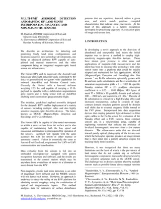
The basic architecture is similar to that of sensors used manner the frames of best resolution are used. Because
in the detection of magnetic fields in currency and of the higher number of variables (UAV speed,
other forms of secure paper, an initial application of the altitude, pitch, roll, raw, etc.) there is a significant
MODE technology and the MagVision sensor/scanner amount of normalization required in order to fit the
product. A laboratory image of an image made with a image stream together in such a way as to have a
MODE sensor (size 12mm x 3mm) scanning a test reasonably uniform scale and “flow” from one image
magnetic strip is shown in Figure 8 below. The image
was produced using a Winnov Videum-AV processor 6
Cf. Roadware Corporation and the ARAN and
card (ISA interface) on a Pentium-200MHz PC. WiseCrax data collection technology for highway
management; web site @ www.roadware.com
5. to the next in both the x and y axes. This critical stage landmines indicated over the background video map
of image processing is necessary in order for both the produced from the Falcon video coverage. Each such
video images and the MODE sensor data synchronized tentative landmine element will act as a “hot” graphical
for post-processing pattern detection. link that an operator can use to bring up in tabular
form, with associated video and MODE image detail,
all the source features pertaining to that region of the
7. PATTERN DETECTION surveyed landscape, using a standard browser-type
graphical user interface.
There are three stages to the pattern detection process
applied to the results of a Falcon flight. The first stage This work has been supported by MODIS Corporation
is mapping and feature detection. A grid is graphically and Silicon Dominion Computing, Inc.
superimposed upon the video data collected and each
crosspoint has a specific spatial coordinate originating
from the GPS record. A sequence of image 8. REFERENCES
transformations is applied to the video map on an
interactive display during which process the operator 1. M. Dudziak and A. Chervonenkis, 1998, “Design of
can identify and mark particular features that are Magneto-Optic Wide-Area Arrays for Deep-Space
recognizable or indicative of possible disturbance. EMF Studies and Power System Control”,
This is a semi-automated, semi-interactive step that International Aerospace and Astronautics Conference,
results in a set of feature elements being recorded in Aosta, IT ‘98
the Access database employed for this purpose.
Currently both ArcView and GeoMedia are being 2. E. M. Johansson and J. E. Mast, 1994, “Three-
evaluated for use in this stage. dimensional ground penetrating radar imaging using
synthetic aperture time-domain focusing”, SPIE JEM
The second stage involves the automated correlation of Conference ’94
the MODE data with the feature database. Each
MODE frame has GPS coordinates and following a 3. J. E. Mast and E. M. Johansson, 1994, “Three-
battery of thresholding and convolution steps to isolate dimensional ground penetrating radar imaging using
potential magnetic features a new feature histogram is multi-frequency diffraction tomography”, SPIE JEM
constructed for each element of interest. This Conference ’94
histogram has the following characteristics:
4. A. Chervonenkis, N. Kiryukhin, and V. Nikerov,
feature diameter 1991, “High-speed coherent optical correlator based on
feature area two MOSLMs”, SPIE Vol. 1614 (1991), 206-209
maximum density
average density 5. V. Nikerov, Yu. Polyakova, and A. Chervonenkis,
characteristic polygon 1991, “Double MOSLM neural-like coherent optical
maximum brightness processor for distorted image recognition”, SPIE Vol.
average brightness 1614 (1991), 210-215
refractivity index
number of near neighbors} multiple 6. V. Nikerov, N. Kiryukhin, Yu. Polyakova, A.
directions of near neighbors} multiple Chervonenkis, and A. Ayrapetov, 1992, “Spatial
distance of near neighbors} multiple filtering on the base of two magnetooptic SLMs”, Adv.
in Magneto-optics II, Proc. 2nd Int. Symp. Magneto-
The third stage consists of creating an association pair Optics, Vol. 18, Supplement, No. S1 (1992), 449-452
database in ascii tabular format that is used as input to
a software-based pattern recognition engine known as 7. M. Dudziak, A. Chervonenkis, and M. Pitkanen,
HAL (Holographic Associative Learning). The 1998, “A family of microinstruments for incorporation
algorithms in HAL are derived in part from into smart materials, energy management, and
[Sutherland, 1990] and related work in applying digital biomedicine for space missions”, NanoSpace ’98
holographic models to statistical clustering techniques (preprint available)
and unsupervised neural networks. The HAL
introduces the role of external pilot training signals to 8. A. Chervonenkis and M. Dudziak, 1998, “High
enhance synchronization among oscillating clusters Sensitivity Magneto-Optic Devices for Weak Magnetic
where each cluster is a grouping of associated feature Field Measurements and Localization”, 2nd Magneto-
elements and categorizations, in this case types of Optics Conference and Workshop, Moscow State
known landmine features, geographic elements, or University (preprint available)
probable image noise. The pattern detection process is
an element of research currently in progress. The 9. J. Sutherland, 1990, “A Holographic Model of
output of the detector software is a modified ArcView Memory, Learning, and Expression”, Intl. J. of Neural
type graphical map with the tentative locations of Systems, Vol. 1, No. 3 (1990), 259-67
6.
7. FIG. 1 --- Hornet UAV in flight (Virginia, 1997) with Canon 8mm videocam and RF control mounted
(courtesy Bert Wagner Air Platforms Unlimited)
FIG. 2 --- ACF-100F Orion (courtesy Orion Systems) FIG. 3 --- Hummingbird UAV (courtesy Aerobotics Corp.)
FIGURE 4 --- Highway accident scene filmed by Hornet UAV (Bert Wagner of Air Platforms Unlimited)
8. Runners attached to Tracks or guardrails
E-PAC module shell and on E-PAC cage
running through tracks built-in to forward
on top and sides of frame of UAV
module
Open equipment area for attaching electronics and sensing
apparatus. All connectivity is via E-PAC interfaces and
communicates with processor onboard or at ground station(s).
Open bay for sensor access. Entire E-
PAC bottom is open, as are front and
rear panels.
FIG. 5 --- Basic schematic of E-PAC module and cage assembly for FALCON modified UAV
PWR GND
PARALLEL
SERIAL2 SERIAL2
MVIDOUT
SVIDOUT
FOPTIN1 FOPTIN2 FOPTOUT1 FOPTOUT2
FIG. 6 --- Basic schematic of E-PAC module and cage assembly for FALCON modified UAV
9. UAV
Main
GPS Polarize Battery
Receiver Voice link Data link from
from groundstation d light
(serial out) source
E-PAC
Module
ViA Pentium PC main system
EM shield housing
3.2GB disk drive
Enhancing
Perm-Magnet
30 watt-
hour Canon Canon MODE Sensor
Battery Videocam Videocam (B/W)
(Color)
FIGURE 7 --- Basic system architecture for MODE + Video Mapping of suspected Minefield areas
FIG. 8 --- Laboratory image (magnified 10x) of test high-coercivity magnetic strip
Scanner Rails
Adjustable Rail
SampleRetainer Scanner Spacers Sample Bed
Drive
Assembly
Motor
Drive Chain
Chain
Sample Retainer
Retainer/Pulley Scanner I/O Cable Drive Control
Cable
FIG. 9 --- MODE Development Workbench Schematic Diagram