SlideShare a Scribd company logo
1 of 30
Download to read offline
Chapter 14
14-1
d =
N
P
=
22
6
= 3.667 in
Table 14-2: Y = 0.331
V =
πdn
12
=
π(3.667)(1200)
12
= 1152 ft/min
Eq. (14-4b): Kv =
1200 + 1152
1200
= 1.96
Wt
=
T
d/2
=
63 025H
nd/2
=
63 025(15)
1200(3.667/2)
= 429.7 lbf
Eq. (14-7):
σ =
KvWt P
FY
=
1.96(429.7)(6)
2(0.331)
= 7633 psi = 7.63 kpsi Ans.
14-2
d =
16
12
= 1.333 in, Y = 0.296
V =
π(1.333)(700)
12
= 244.3 ft/min
Eq. (14-4b): Kv =
1200 + 244.3
1200
= 1.204
Wt
=
63 025H
nd/2
=
63 025(1.5)
700(1.333/2)
= 202.6 lbf
Eq. (14-7):
σ =
KvWt P
FY
=
1.204(202.6)(12)
0.75(0.296)
= 13 185 psi = 13.2 kpsi Ans.
14-3
d = mN = 1.25(18) = 22.5 mm, Y = 0.309
V =
π(22.5)(10−3
)(1800)
60
= 2.121 m/s
Eq. (14-6b): Kv =
6.1 + 2.121
6.1
= 1.348
Wt
=
60H
πdn
=
60(0.5)(103
)
π(22.5)(10−3)(1800)
= 235.8 N
Eq. (14-8): σ =
KvWt
FmY
=
1.348(235.8)
12(1.25)(0.309)
= 68.6 MPa Ans.
shi20396_ch14.qxd 8/20/03 12:43 PM Page 360
Chapter 14 361
14-4
d = 5(15) = 75 mm, Y = 0.290
V =
π(75)(10−3
)(200)
60
= 0.7854 m/s
Assume steel and apply Eq. (14-6b):
Kv =
6.1 + 0.7854
6.1
= 1.129
Wt
=
60H
πdn
=
60(5)(103
)
π(75)(10−3)(200)
= 6366 N
Eq. (14-8): σ =
KvWt
FmY
=
1.129(6366)
60(5)(0.290)
= 82.6 MPa Ans.
14-5
d = 1(16) = 16 mm, Y = 0.296
V =
π(16)(10−3
)(400)
60
= 0.335 m/s
Assume steel and apply Eq. (14-6b):
Kv =
6.1 + 0.335
6.1
= 1.055
Wt
=
60H
πdn
=
60(0.15)(103
)
π(16)(10−3)(400)
= 447.6 N
Eq. (14-8): F =
KvWt
σmY
=
1.055(447.6)
150(1)(0.296)
= 10.6 mm
From Table A-17, use F = 11 mm Ans.
14-6
d = 1.5(17) = 25.5 mm, Y = 0.303
V =
π(25.5)(10−3
)(400)
60
= 0.534 m/s
Eq. (14-6b): Kv =
6.1 + 0.534
6.1
= 1.088
Wt
=
60H
πdn
=
60(0.25)(103
)
π(25.5)(10−3)(400)
= 468 N
Eq. (14-8): F =
KvWt
σmY
=
1.088(468)
75(1.5)(0.303)
= 14.9 mm
Use F = 15 mm Ans.
shi20396_ch14.qxd 8/20/03 12:43 PM Page 361
362 Solutions Manual • Instructor’s Solution Manual to Accompany Mechanical Engineering Design
14-7
d =
24
5
= 4.8 in, Y = 0.337
V =
π(4.8)(50)
12
= 62.83 ft/min
Eq. (14-4b): Kv =
1200 + 62.83
1200
= 1.052
Wt
=
63 025H
nd/2
=
63 025(6)
50(4.8/2)
= 3151 lbf
Eq. (14-7): F =
KvWt P
σY
=
1.052(3151)(5)
20(103)(0.337)
= 2.46 in
Use F = 2.5 in Ans.
14-8
d =
16
5
= 3.2 in, Y = 0.296
V =
π(3.2)(600)
12
= 502.7 ft/min
Eq. (14-4b): Kv =
1200 + 502.7
1200
= 1.419
Wt
=
63 025(15)
600(3.2/2)
= 984.8 lbf
Eq. (14-7): F =
KvWt P
σY
=
1.419(984.8)(5)
10(103)(0.296)
= 2.38 in
Use F = 2.5 in Ans.
14-9 Try P = 8 which gives d = 18/8 = 2.25 in and Y = 0.309.
V =
π(2.25)(600)
12
= 353.4 ft/min
Eq. (14-4b): Kv =
1200 + 353.4
1200
= 1.295
Wt
=
63 025(2.5)
600(2.25/2)
= 233.4 lbf
Eq. (14-7): F =
KvWt P
σY
=
1.295(233.4)(8)
10(103)(0.309)
= 0.783 in
shi20396_ch14.qxd 8/20/03 12:43 PM Page 362
Chapter 14 363
Using coarse integer pitches from Table 13-2, the following table is formed.
P d V Kv Wt
F
2 9.000 1413.717 2.178 58.356 0.082
3 6.000 942.478 1.785 87.535 0.152
4 4.500 706.858 1.589 116.713 0.240
6 3.000 471.239 1.393 175.069 0.473
8 2.250 353.429 1.295 233.426 0.782
10 1.800 282.743 1.236 291.782 1.167
12 1.500 235.619 1.196 350.139 1.627
16 1.125 176.715 1.147 466.852 2.773
Other considerations may dictate the selection. Good candidates are P = 8 (F = 7/8 in)
and P = 10 (F = 1.25 in). Ans.
14-10 Try m = 2 mm which gives d = 2(18) = 36 mm and Y = 0.309.
V =
π(36)(10−3
)(900)
60
= 1.696 m/s
Eq. (14-6b): Kv =
6.1 + 1.696
6.1
= 1.278
Wt
=
60(1.5)(103
)
π(36)(10−3)(900)
= 884 N
Eq. (14-8): F =
1.278(884)
75(2)(0.309)
= 24.4 mm
Using the preferred module sizes from Table 13-2:
m d V Kv Wt
F
1.00 18.0 0.848 1.139 1768.388 86.917
1.25 22.5 1.060 1.174 1414.711 57.324
1.50 27.0 1.272 1.209 1178.926 40.987
2.00 36.0 1.696 1.278 884.194 24.382
3.00 54.0 2.545 1.417 589.463 12.015
4.00 72.0 3.393 1.556 442.097 7.422
5.00 90.0 4.241 1.695 353.678 5.174
6.00 108.0 5.089 1.834 294.731 3.888
8.00 144.0 6.786 2.112 221.049 2.519
10.00 180.0 8.482 2.391 176.839 1.824
12.00 216.0 10.179 2.669 147.366 1.414
16.00 288.0 13.572 3.225 110.524 0.961
20.00 360.0 16.965 3.781 88.419 0.721
25.00 450.0 21.206 4.476 70.736 0.547
32.00 576.0 27.143 5.450 55.262 0.406
40.00 720.0 33.929 6.562 44.210 0.313
50.00 900.0 42.412 7.953 35.368 0.243
Other design considerations may dictate the size selection. For the present design,
m = 2 mm (F = 25 mm) is a good selection. Ans.
shi20396_ch14.qxd 8/20/03 12:43 PM Page 363
364 Solutions Manual • Instructor’s Solution Manual to Accompany Mechanical Engineering Design
14-11
dP =
22
6
= 3.667 in, dG =
60
6
= 10 in
V =
π(3.667)(1200)
12
= 1152 ft/min
Eq. (14-4b): Kv =
1200 + 1152
1200
= 1.96
Wt
=
63 025(15)
1200(3.667/2)
= 429.7 lbf
Table 14-8: Cp = 2100 psi
Eq. (14-12): r1 =
3.667 sin 20°
2
= 0.627 in, r2 =
10 sin 20°
2
= 1.710 in
Eq. (14-14): σC = −Cp
KvWt
F cos φ
1
r1
+
1
r2
1/2
= −2100
1.96(429.7)
2 cos 20°
1
0.627
+
1
1.710
1/2
= −65.6(103
) psi = −65.6 kpsi Ans.
14-12
dP =
16
12
= 1.333 in, dG =
48
12
= 4 in
V =
π(1.333)(700)
12
= 244.3 ft/min
Eq. (14-4b): Kv =
1200 + 244.3
1200
= 1.204
Wt
=
63 025(1.5)
700(1.333/2)
= 202.6 lbf
Table 14-8: Cp = 2100
√
psi
Eq. (14-12): r1 =
1.333 sin 20°
2
= 0.228 in, r2 =
4 sin 20°
2
= 0.684 in
Eq. (14-14):
σC = −2100
1.202(202.6)
F cos 20°
1
0.228
+
1
0.684
1/2
= −100(103
)
F =
2100
100(103)
2
1.202(202.6)
cos 20°
1
0.228
+
1
0.684
= 0.668 in
Use F = 0.75 in Ans.
shi20396_ch14.qxd 8/20/03 12:43 PM Page 364
Chapter 14 365
14-13
dP =
24
5
= 4.8 in, dG =
48
5
= 9.6 in
Eq. (14-4a):
V =
π(4.8)(50)
12
= 62.83 ft/min
Kv =
600 + 62.83
600
= 1.105
Wt
=
63 025H
50(4.8/2)
= 525.2H
Table 14-8: Cp = 1960
√
psi
Eq. (14-12): r1 =
4.8 sin 20◦
2
= 0.821 in, r2 = 2r1 = 1.642 in
Eq. (14-14): −100(103
) = −1960
1.105(525.2H)
2.5 cos 20◦
1
0.821
+
1
1.642
1/2
H = 5.77 hp Ans.
14-14
dP = 4(20) = 80 mm, dG = 4(32) = 128 mm
V =
π(80)(10−3
)(1000)
60
= 4.189 m/s
Kv =
3.05 + 4.189
3.05
= 2.373
Wt
=
60(10)(103
)
π(80)(10−3)(1000)
= 2387 N
Cp = 163
√
MPa
r1 =
80 sin 20°
2
= 13.68 mm, r2 =
128 sin 20°
2
= 21.89 mm
σC = −163
2.373(2387)
50 cos 20°
1
13.68
+
1
21.89
1/2
= −617 MPa Ans.
14-15 The pinion controls the design.
Bending YP = 0.303, YG = 0.359
dP =
17
12
= 1.417 in, dG =
30
12
= 2.500 in
V =
πdPn
12
=
π(1.417)(525)
12
= 194.8 ft/min
Eq. (14-4b): Kv =
1200 + 194.8
1200
= 1.162
Eq. (7-8): Se = 0.504(76) = 38 300 psi
Eq. (7-18): ka = 2.70(76)−0.265
= 0.857
Eq. (14-6a):
Table 14-8:
Eq. (14-12):
Eq. (14-14):
shi20396_ch14.qxd 8/20/03 12:43 PM Page 365
366 Solutions Manual • Instructor’s Solution Manual to Accompany Mechanical Engineering Design
l =
2.25
Pd
=
2.25
12
= 0.1875 in
x =
3YP
2P
=
3(0.303)
2(12)
= 0.0379 in
t = 4(0.1875)(0.0379) = 0.1686 in
de = 0.808 0.875(0.1686) = 0.310 in
kb =
0.310
0.30
−0.107
= 0.996
kc = kd = ke = 1, kf1
= 1.65
rf =
0.300
12
= 0.025 in
r
d
=
rf
t
=
0.025
0.1686
= 0.148
Approximate D/d = ∞ with D/d = 3; from Fig. A-15-6, Kt = 1.68.
Eq. (7-35): Kf =
1.68
1 +
2
√
0.025
1.68 − 1
1.68
4
76
= 1.323
Miscellaneous-Effects Factor:
kf = kf 1kf 2 = 1.65
1
1.323
= 1.247
Se = 0.857(0.996)(1)(1)(1)(1.247)(38 300)
= 40 770 psi
σall =
40 770
2.25
= 18 120 psi
Wt
=
FYPσall
Kv Pd
=
0.875(0.303)(18 120)
1.162(12)
= 345 lbf
H =
345(194.8)
33 000
= 2.04 hp Ans.
Wear
ν1 = ν2 = 0.292, E1 = E2 = 30(106
) psi
Eq. (14-14): Cp = 2300 psi
r1 =
dP
2
sin φ =
1.417
2
sin 20° = 0.242 in
r2 =
dG
2
sin φ =
2.500
2
sin 20° = 0.428
1
r1
+
1
r2
=
1
0.242
+
1
0.428
= 6.469 in−1
Eq. (14-12):
Eq. (7-17):
Eq. (14-3):
Eq. (7-24):
Eq. (7-19):
shi20396_ch14.qxd 8/20/03 12:43 PM Page 366
Chapter 14 367
From Eq. (7-68),
(SC)108 = 0.4HB − 10 kpsi
= [0.4(149) − 10](103
) = 49 600 psi
σC,all =
−49 600
√
2.25
= −33 067 psi
Wt
=
−33 067
2300
2
0.875 cos 20°
1.162(6.469)
= 22.6 lbf
H =
22.6(194.8)
33 000
= 0.133 hp Ans.
Rating power (pinion controls):
H1 = 2.04 hp
H2 = 0.133 hp
Hall = (min 2.04, 0.133) = 0.133 hp Ans.
14-16 Pinion controls: YP = 0.322, YG = 0.447
Bending dP = 20/3 = 6.667 in, dG = 33.333 in
V = πdPn/12 = π(6.667)(870)/12 = 1519 ft/min
Kv = (1200 + 1519)/1200 = 2.266
Se = 0.504(113) = 56.950 kpsi = 56 950 psi
ka = 2.70(113)−0.265
= 0.771
l = 2.25/Pd = 2.25/3 = 0.75 in
x = 3(0.322)/[2(3)] = 0.161 in
t = 4(0.75)(0.161) = 0.695 in
de = 0.808 2.5(0.695) = 1.065 in
kb = (1.065/0.30)−0.107
= 0.873
kc = kd = ke = 1
rf = 0.300/3 = 0.100 in
r
d
=
rf
t
=
0.100
0.695
= 0.144
From Table A-15-6, Kt = 1.75; Eq. (7-35): Kf = 1.597
kf 2 = 1/1.597, kf = kf 1kf 2 = 1.65/1.597 = 1.033
Se = 0.771(0.873)(1)(1)(1)(1.033)(56 950) = 39 600 psi
σall = 39 600/1.5 = 26 400 psi
Wt
=
FYPσall
Kv Pd
=
2.5(0.322)(26 400)
2.266(3)
= 3126 lbf
H = Wt
V/33 000 = 3126(1519)/33 000 = 144 hp Ans.
shi20396_ch14.qxd 8/20/03 12:43 PM Page 367
368 Solutions Manual • Instructor’s Solution Manual to Accompany Mechanical Engineering Design
Wear
Cp = 2300 psi
r1 = (6.667/2) sin 20° = 1.140 in
r2 = (33.333/2) sin 20° = 5.700 in
SC = [0.4(262) − 10](103
) = 94 800 psi
σC,all = −SC/
√
nd = −94.800/
√
1.5 = −77 404 psi
Wt
=
σC,all
Cp
2
F cos φ
Kv
1
1/r1 + 1/r2
=
−77 404
2300
2
2.5 cos 20°
2.266
1
1/1.140 + 1/5.700
= 1115 lbf
H =
Wt V
33 000
=
1115(1519)
33 000
= 51.3 hp Ans.
For 108
cycles (revolutions of the pinion), the power based on wear is 51.3 hp.
Rating power–pinion controls
H1 = 144 hp
H2 = 51.3 hp
Hrated = min(144, 51.3) = 51.3 hp Ans.
14-17 Given: φ = 20°, n = 1145 rev/min, m = 6 mm, F = 75 mm, NP = 16 milled teeth,
NG = 30T, Sut = 900 MPa, HB = 260, nd = 3, YP = 0.296, and YG = 0.359.
Pinion bending
dP = mNP = 6(16) = 96 mm
dG = 6(30) = 180 mm
V =
πdPn
12
=
π(96)(1145)(10−3
)(12)
(12)(60)
= 5.76 m/s
Eq. (14-6b): Kv =
6.1 + 5.76
6.1
= 1.944
Se = 0.504(900) = 453.6 MPa
a = 4.45, b = −0.265
ka = 4.51(900)−0.265
= 0.744
l = 2.25m = 2.25(6) = 13.5 mm
x = 3Ym/2 = 3(0.296)6/2 = 2.664 mm
t =
√
4lx = 4(13.5)(2.664) = 12.0 mm
de = 0.808 75(12.0) = 24.23 mm
Table 14-8:
Eq. (14-12):
Eq. (7-68):
shi20396_ch14.qxd 8/20/03 12:43 PM Page 368
Chapter 14 369
kb =
24.23
7.62
−0.107
= 0.884
kc = kd = ke = 1
rf = 0.300m = 0.300(6) = 1.8 mm
From Fig. A-15-6 for r/d = rf /t = 1.8/12 = 0.15, Kt = 1.68.
Kf =
1.68
1 + 2
√
1.8 [(1.68 − 1)/1.68](139/900)
= 1.537
kf 1 = 1.65 (Gerber failure criterion)
kf 2 = 1/Kf = 1/1.537 = 0.651
kf = kf 1kf 2 = 1.65(0.651) = 1.074
Se = 0.744(0.884)(1)(1)(1)(1.074)(453.6) = 320.4 MPa
σall =
Se
nd
=
320.4
1.3
= 246.5 MPa
Eq. (14-8): Wt
=
FYmσall
Kv
=
75(0.296)(6)(246.5)
1.944
= 16 890 N
H =
Tn
9.55
=
16 890(96/2)(1145)
9.55(106)
= 97.2 kW Ans.
Wear: Pinion and gear
Eq. (14-12): r1 = (96/2) sin 20◦
= 16.42 mm
r2 = (180/2) sin 20◦
= 30.78 mm
Table 14-8: Cp ˙= 191
√
MPa
Eq. (7-68): SC = 6.89[0.4(260) − 10] = 647.7 MPa
σC,all = −
647.7
√
1.3
= −568 MPa
Eq. (14-14): Wt
=
σC,all
Cp
2
F cos φ
Kv
1
1/r1 + 1/r2
=
−568
191
2
75 cos 20◦
1.944
1
1/16.42 + 1/30.78
= 3433 N
T =
WtdP
2
=
3433(96)
2
= 164 784 N · mm = 164.8 N · m
H =
Tn
9.55
=
164.8(1145)
9.55
= 19 758.7 W = 19.8 kW Ans.
Thus, wear controls the gearset power rating; H = 19.8 kW. Ans.
shi20396_ch14.qxd 8/20/03 12:43 PM Page 369
370 Solutions Manual • Instructor’s Solution Manual to Accompany Mechanical Engineering Design
14-18 Preliminaries: NP = 17, NG = 51
dP =
N
Pd
=
17
6
= 2.833 in
dG =
51
6
= 8.500 in
V = πdPn/12 = π(2.833)(1120)/12 = 830.7 ft/min
Eq. (14-4b): Kv = (1200 + 830.7)/1200 = 1.692
σall =
Sy
nd
=
90 000
2
= 45 000 psi
Table 14-2: YP = 0.303, YG = 0.410
Eq. (14-7): Wt
=
FYPσall
Kv Pd
=
2(0.303)(45 000)
1.692(6)
= 2686 lbf
H =
WtV
33 000
=
2686(830.7)
33 000
= 67.6 hp
Based on yielding in bending, the power is 67.6 hp.
(a) Pinion fatigue
Bending
Se = 0.504(232/2) = 58 464 psi
a = 2.70, b = −0.265, ka = 2.70(116)−0.265
= 0.766
Table 13-1: l =
1
Pd
+
1.25
Pd
=
2.25
Pd
=
2.25
6
= 0.375 in
Eq. (14-3): x =
3YP
2Pd
=
3(0.303)
2(6)
= 0.0758
t =
√
4lx = 4(0.375)(0.0758) = 0.337 in
de = 0.808
√
Ft = 0.808 2(0.337) = 0.663 in
kb =
0.663
0.30
−0.107
= 0.919
kc = kd = ke = 1. Assess two components contributing to kf . First, based upon
one-way bending and the Gerber failure criterion, kf 1 = 1.65. Second, due to stress-
concentration,
rf =
0.300
Pd
=
0.300
6
= 0.050 in
Fig. A-15-6:
r
d
=
rf
t
=
0.05
0.338
= 0.148
shi20396_ch14.qxd 8/20/03 12:43 PM Page 370
Chapter 14 371
Estimate D/d = ∞ by setting D/d = 3, Kt = 1.68. From Eq. (7-35) and Table 7-8,
Kf =
1.68
1 + 2
√
0.05 [(1.68 − 1)/1.68](4/116)
= 1.494
kf 2 =
1
Kf
=
1
1.494
= 0.669
kf = kf 1kf 2 = 1.65(0.669) = 1.104
Se = 0.766(0.919)(1)(1)(1)(1.104)(58 464) = 45 436 psi
σall =
Se
nd
=
45 436
2
= 22 718 psi
Wt
=
FYPσall
Kv Pd
=
2(0.303)(22 718)
1.692(6)
= 1356 lbf
H =
Wt V
33 000
=
1356(830.7)
33 000
= 34.1 hp Ans.
(b) Pinion fatigue
Wear
From Table A-5 for steel: ν = 0.292, E = 30(106
) psi
Eq. (14-13) or Table 14-8:
Cp =
1
2π[(1 − 0.2922)/30(106)]
1/2
= 2285 psi
In preparation for Eq. (14-14):
Eq. (14-12): r1 =
dP
2
sin φ =
2.833
2
sin 20◦
= 0.485 in
r2 =
dG
2
sin φ =
8.500
2
sin 20◦
= 1.454 in
1
r1
+
1
r2
=
1
0.485
+
1
1.454
= 2.750 in
Eq. (7-68): (SC)108 = 0.4HB − 10 kpsi
In terms of gear notation
σC = [0.4(232) − 10]103
= 82 800 psi
We will introduce the design factor of nd = 2 and apply it to the load Wt
by dividing
by
√
2.
σC,all = −
σc
√
2
= −
82 800
√
2
= −58 548 psi
shi20396_ch14.qxd 8/20/03 12:43 PM Page 371
372 Solutions Manual • Instructor’s Solution Manual to Accompany Mechanical Engineering Design
Solve Eq. (14-14) for Wt
:
Wt
=
−58 548
2285
2
2 cos 20◦
1.692(2.750)
= 265 lbf
Hall =
265(830.7)
33 000
= 6.67 hp Ans.
For 108
cycles (turns of pinion), the allowable power is 6.67 hp.
(c) Gear fatigue due to bending and wear
Bending
Eq. (14-3): x =
3YG
2Pd
=
3(0.4103)
2(6)
= 0.1026 in
t = 4(0.375)(0.1026) = 0.392 in
de = 0.808 2(0.392) = 0.715 in
kb =
0.715
0.30
−0.107
= 0.911
kc = kd = ke = 1
r
d
=
rf
t
=
0.050
0.392
= 0.128
Approximate D/d = ∞ by setting D/d = 3 for Fig. A-15-6; Kt = 1.80. Use Kf =
1.583.
kf 2 =
1
1.583
= 0.632, kf = 1.65(0.632) = 1.043
Se = 0.766(0.911)(1)(1)(1)(1.043)(58 464) = 42 550 psi
σall =
Se
2
=
42 550
2
= 21 275 psi
Wt
=
2(0.4103)(21 275)
1.692(6)
= 1720 lbf
Hall =
1720(830.7)
33 000
= 43.3 hp Ans.
The gear is thus stronger than the pinion in bending.
Wear Since the material of the pinion and the gear are the same, and the contact
stresses are the same, the allowable power transmission of both is the same. Thus,
Hall = 6.67 hp for 108
revolutions of each. As yet, we have no way to establish SC for
108
/3 revolutions.
shi20396_ch14.qxd 8/20/03 12:43 PM Page 372
Chapter 14 373
(d) Pinion bending: H1 = 34.1 hp
Pinion wear: H2 = 6.67 hp
Gear bending: H3 = 43.3 hp
Gear wear: H4 = 6.67 hp
Power rating of the gear set is thus
Hrated = min(34.1, 6.67, 43.3, 6.67) = 6.67 hp Ans.
14-19 dP = 16/6 = 2.667 in, dG = 48/6 = 8 in
V =
π(2.667)(300)
12
= 209.4 ft/min
Wt
=
33 000(5)
209.4
= 787.8 lbf
Assuming uniform loading, Ko = 1. From Eq. (14-28),
Qv = 6, B = 0.25(12 − 6)2/3
= 0.8255
A = 50 + 56(1 − 0.8255) = 59.77
Eq. (14-27):
Kv =
59.77 +
√
209.4
59.77
0.8255
= 1.196
From Table 14-2,
NP = 16T, YP = 0.296
NG = 48T, YG = 0.4056
From Eq. (a), Sec. 14-10 with F = 2 in
(Ks)P = 1.192
2
√
0.296
6
0.0535
= 1.088
(Ks)G = 1.192
2
√
0.4056
6
0.0535
= 1.097
From Eq. (14-30) with Cmc = 1
Cpf =
2
10(2.667)
− 0.0375 + 0.0125(2) = 0.0625
Cpm = 1, Cma = 0.093 (Fig. 14-11), Ce = 1
Km = 1 + 1[0.0625(1) + 0.093(1)] = 1.156
Assuming constant thickness of the gears → KB = 1
mG = NG/NP = 48/16 = 3
With N (pinion) = 108
cycles and N (gear) = 108
/3, Fig. 14-14 provides the relations:
(YN )P = 1.3558(108
)−0.0178
= 0.977
(YN )G = 1.3558(108
/3)−0.0178
= 0.996
shi20396_ch14.qxd 8/20/03 12:43 PM Page 373
374 Solutions Manual • Instructor’s Solution Manual to Accompany Mechanical Engineering Design
Fig. 14-6: JP = 0.27, JG ˙= 0.38
From Table 14-10 for R = 0.9, KR = 0.85
KT = Cf = 1
Eq. (14-23) with mN = 1 I =
cos 20◦ sin 20◦
2
3
3 + 1
= 0.1205
Table 14-8: Cp = 2300 psi
Strength: Grade 1 steel with HBP = HBG = 200
Fig. 14-2: (St)P = (St)G = 77.3(200) + 12 800 = 28 260 psi
Fig. 14-5: (Sc)P = (Sc)G = 322(200) + 29 100 = 93 500 psi
Fig. 14-15: (ZN )P = 1.4488(108
)−0.023
= 0.948
(ZN )G = 1.4488(108
/3)−0.023
= 0.973
Sec. 14-12: HBP/HBG = 1 ∴ CH = 1
Pinion tooth bending
Eq. (14-15):
(σ)P = Wt
KoKv Ks
Pd
F
Km KB
J
= 787.8(1)(1.196)(1.088)
6
2
(1.156)(1)
0.27
= 13 167 psi Ans.
Factor of safety from Eq. (14-41)
(SF)P =
StYN /(KT KR)
σ
=
28 260(0.977)/[(1)(0.85)]
13 167
= 2.47 Ans.
Gear tooth bending
(σ)G = 787.8(1)(1.196)(1.097)
6
2
(1.156)(1)
0.38
= 9433 psi Ans.
(SF)G =
28 260(0.996)/[(1)(0.85)]
9433
= 3.51 Ans.
Pinion tooth wear
Eq. (14-16): (σc)P = Cp Wt
KoKv Ks
Km
dP F
Cf
I
1/2
P
= 2300 787.8(1)(1.196)(1.088)
1.156
2.667(2)
1
0.1205
1/2
= 98 760 psi Ans.
Eq. (14-42):
(SH )P =
Sc ZN /(KT KR)
σc P
=
93 500(0.948)/[(1)(0.85)]
98 760
= 1.06 Ans.
shi20396_ch14.qxd 8/20/03 12:43 PM Page 374
Chapter 14 375
Gear tooth wear
(σc)G =
(Ks)G
(Ks)P
1/2
(σc)P =
1.097
1.088
1/2
(98 760) = 99 170 psi Ans.
(SH )G =
93 500(0.973)(1)/[(1)(0.85)]
99 170
= 1.08 Ans.
The hardness of the pinion and the gear should be increased.
14-20 dP = 2.5(20) = 50 mm, dG = 2.5(36) = 90 mm
V =
πdPnP
60
=
π(50)(10−3
)(100)
60
= 0.2618 m/s
Wt
=
60(120)
π(50)(10−3)(100)
= 458.4 N
Eq. (14-28): Ko = 1, Qv = 6, B = 0.25(12 − 6)2/3
= 0.8255
A = 50 + 56(1 − 0.8255) = 59.77
Eq. (14-27): Kv =
59.77 +
√
200(0.2618)
59.77
0.8255
= 1.099
Table 14-2: YP = 0.322, YG = 0.3775
Similar to Eq. (a) of Sec. 14-10 but for SI units:
Ks =
1
kb
= 0.8433 mF
√
Y
0.0535
(Ks)P = 0.8433 2.5(18)
√
0.322
0.0535
= 1.003 use 1
(Ks)G = 0.8433 2.5(18)
√
0.3775
0.0535
> 1 use 1
Cmc = 1, F = 18/25.4 = 0.709 in, Cpf =
18
10(50)
− 0.025 = 0.011
Cpm = 1, Cma = 0.247 + 0.0167(0.709) − 0.765(10−4
)(0.7092
) = 0.259
Ce = 1
KH = 1 + 1[0.011(1) + 0.259(1)] = 1.27
Eq. (14-40): KB = 1, mG = NG/NP = 36/20 = 1.8
Fig. 14-14: (YN )P = 1.3558(108
)−0.0178
= 0.977
(YN )G = 1.3558(108
/1.8)−0.0178
= 0.987
Fig. 14-6: (YJ )P = 0.33, (YJ )G = 0.38
Eq. (14-38): YZ = 0.658 − 0.0759 ln(1 − 0.95) = 0.885
Yθ = ZR = 1
shi20396_ch14.qxd 8/20/03 12:43 PM Page 375
376 Solutions Manual • Instructor’s Solution Manual to Accompany Mechanical Engineering Design
Eq. (14-23) with mN = 1:
ZI =
cos 20◦ sin 20◦
2
1.8
1.8 + 1
= 0.103
Table 14-8: ZE = 191
√
MPa
Strength Grade 1 steel, HBP = HBG = 200
Fig. 14-2: (σF P)P = (σF P)G = 0.533(200) + 88.3 = 194.9 MPa
Fig. 14-5: (σH P)P = (σH P)G = 2.22(200) + 200 = 644 MPa
Fig. 14-15: (ZN )P = 1.4488(108
)−0.023
= 0.948
(ZN )G = 1.4488(108
/1.8)−0.023
= 0.961
HBP/HBG = 1 ∴ ZW = 1
Pinion tooth bending
(σ)P = Wt
KoKv Ks
1
bmt
KH KB
YJ P
= 458.4(1)(1.099)(1)
1
18(2.5)
1.27(1)
0.33
= 43.08 MPa Ans.
(SF)P =
σF P
σ
YN
Yθ YZ P
=
194.9
43.08
0.977
1(0.885)
= 4.99 Ans.
Gear tooth bending
(σ)G = 458.4(1)(1.099)(1)
1
18(2.5)
1.27(1)
0.38
= 37.42 MPa Ans.
(SF)G =
194.9
37.42
0.987
1(0.885)
= 5.81 Ans.
Pinion tooth wear
(σc)P = ZE Wt KoKv Ks
KH
dw1b
ZR
ZI
P
= 191 458.4(1)(1.099)(1)
1.27
50(18)
1
0.103
= 501.8 MPa Ans.
(SH )P =
σH P
σc
ZN ZW
Yθ YZ P
=
644
501.8
0.948(1)
1(0.885)
= 1.37 Ans.
Gear tooth wear
(σc)G =
(Ks)G
(Ks)P
1/2
(σc)P =
1
1
1/2
(501.8) = 501.8 MPa Ans.
(SH )G =
644
501.8
0.961(1)
1(0.885)
= 1.39 Ans.
shi20396_ch14.qxd 8/20/03 12:43 PM Page 376
Chapter 14 377
14-21
Pt = Pn cos ψ = 6 cos 30° = 5.196 teeth/in
dP =
16
5.196
= 3.079 in, dG =
48
16
(3.079) = 9.238 in
V =
π(3.079)(300)
12
= 241.8 ft/min
Wt
=
33 000(5)
241.8
= 682.3 lbf, Kv =
59.77 +
√
241.8
59.77
0.8255
= 1.210
From Prob. 14-19:
YP = 0.296, YG = 0.4056
(Ks)P = 1.088, (Ks)G = 1.097, KB = 1
mG = 3, (YN )P = 0.977, (YN )G = 0.996, KR = 0.85
(St)P = (St)G = 28 260 psi, CH = 1, (Sc)P = (Sc)G = 93 500 psi
(ZN )P = 0.948, (ZN )G = 0.973, Cp = 2300
√
psi
The pressure angle is:
φt = tan−1 tan 20°
cos 30°
= 22.80°
(rb)P =
3.079
2
cos 22.8° = 1.419 in, (rb)G = 3(rb)P = 4.258 in
a = 1/Pn = 1/6 = 0.167 in
Eq. (14-26):
Z =
3.079
2
+ 0.167
2
− 1.4192
1/2
+
9.238
2
+ 0.167
2
− 4.2582
1/2
−
3.079
2
+
9.238
2
sin 22.8°
= 0.9479 + 2.1852 − 2.3865 = 0.7466 Conditions O.K. for use
pN = pn cos φn =
π
6
cos 20° = 0.4920 in
Eq. (14-23): mN =
pN
0.95Z
=
0.492
0.95(0.7466)
= 0.6937
Eq. (14-23): I =
sin 22.8° cos 22.8°
2(0.6937)
3
3 + 1
= 0.193
Fig. 14-7: JP ˙= 0.45, JG ˙= 0.54
shi20396_ch14.qxd 8/20/03 12:43 PM Page 377
378 Solutions Manual • Instructor’s Solution Manual to Accompany Mechanical Engineering Design
Fig. 14-8: Corrections are 0.94 and 0.98
JP = 0.45(0.94) = 0.423, JG = 0.54(0.98) = 0.529
Cmc = 1, Cpf =
2
10(3.079)
− 0.0375 + 0.0125(2) = 0.0525
Cpm = 1, Cma = 0.093, Ce = 1
Km = 1 + (1)[0.0525(1) + 0.093(1)] = 1.146
Pinion tooth bending
(σ)P = 682.3(1)(1.21)(1.088)
5.196
2
1.146(1)
0.423
= 6323 psi Ans.
(SF)P =
28 260(0.977)/[1(0.85)]
6323
= 5.14 Ans.
Gear tooth bending
(σ)G = 682.3(1)(1.21)(1.097)
5.196
2
1.146(1)
0.529
= 5097 psi Ans.
(SF)G =
28 260(0.996)/[1(0.85)]
5097
= 6.50 Ans.
Pinion tooth wear
(σc)P = 2300 682.3(1)(1.21)(1.088)
1.146
3.078(2)
1
0.193
1/2
= 67 700 psi Ans.
(SH )P =
93 500(0.948)/[(1)(0.85)]
67 700
= 1.54 Ans.
Gear tooth wear
(σc)G =
1.097
1.088
1/2
(67 700) = 67 980 psi Ans.
(SH )G =
93 500(0.973)/[(1)(0.85)]
67 980
= 1.57 Ans.
14-22 Given: R = 0.99 at 108
cycles, HB = 232 through-hardening Grade 1, core and case, both
gears. NP = 17T, NG = 51T, YP = 0.303, YG = 0.4103, JP = 0.292, JG = 0.396,
dP = 2.833 in, dG = 8.500 in.
Pinion bending
From Fig. 14-2:
0.99(St)107 = 77.3HB + 12 800
= 77.3(232) + 12 800 = 30 734 psi
shi20396_ch14.qxd 8/20/03 12:43 PM Page 378
Chapter 14 379
Fig. 14-14: YN = 1.6831(108
)−0.0323
= 0.928
V = πdPn/12 = π(2.833)(1120/12) = 830.7 ft/min
KT = KR = 1, SF = 2, SH =
√
2
σall =
30 734(0.928)
2(1)(1)
= 14 261 psi
Qv = 5, B = 0.25(12 − 5)2/3
= 0.9148
A = 50 + 56(1 − 0.9148) = 54.77
Kv =
54.77 +
√
830.7
54.77
0.9148
= 1.472
Ks = 1.192
2
√
0.303
6
0.0535
= 1.089 ⇒ use 1
Km = Cm f = 1 + Cmc(Cpf Cpm + CmaCe)
Cmc = 1
Cpf =
F
10d
− 0.0375 + 0.0125F
=
2
10(2.833)
− 0.0375 + 0.0125(2)
= 0.0581
Cpm = 1
Cma = 0.127 + 0.0158(2) − 0.093(10−4
)(22
) = 0.1586
Ce = 1
Km = 1 + 1[0.0581(1) + 0.1586(1)] = 1.2167
Eq. (14-15):
Kβ = 1
Wt
=
F JPσall
KoKv Ks Pd Km Kβ
=
2(0.292)(14 261)
1(1.472)(1)(6)(1.2167)(1)
= 775 lbf
H =
Wt V
33 000
=
775(830.7)
33 000
= 19.5 hp
Pinion wear
Fig. 14-15: ZN = 2.466N−0.056
= 2.466(108
)−0.056
= 0.879
MG = 51/17 = 3
I =
sin 20◦ cos 20◦
2
3
3 + 1
= 1.205, CH = 1
shi20396_ch14.qxd 8/20/03 12:43 PM Page 379
380 Solutions Manual • Instructor’s Solution Manual to Accompany Mechanical Engineering Design
Fig. 14-5: 0.99(Sc)107 = 322HB + 29 100
= 322(232) + 29 100 = 103 804 psi
σc,all =
103 804(0.879)
√
2(1)(1)
= 64 519 psi
Eq. (14-16): Wt
=
σc,all
Cp
2
FdP I
KoKv Ks KmCf
=
64 519
2300
2
2(2.833)(0.1205)
1(1.472)(1)(1.2167)(1)
= 300 lbf
H =
Wt V
33 000
=
300(830.7)
33 000
= 7.55 hp
The pinion controls therefore Hrated = 7.55 hp Ans.
4-23
l = 2.25/Pd, x =
3Y
2Pd
t =
√
4lx = 4
2.25
Pd
3Y
2Pd
=
3.674
Pd
√
Y
de = 0.808
√
Ft = 0.808 F
3.674
Pd
√
Y = 1.5487
F
√
Y
Pd
kb =


1.5487 F
√
Y/Pd
0.30


−0.107
= 0.8389
F
√
Y
Pd
−0.0535
Ks =
1
kb
= 1.192
F
√
Y
Pd
0.0535
Ans.
14-24 YP = 0.331, YG = 0.422, JP = 0.345, JG = 0.410, Ko = 1.25. The service conditions
are adequately described by Ko. Set SF = SH = 1.
dP = 22/4 = 5.500 in
dG = 60/4 = 15.000 in
V =
π(5.5)(1145)
12
= 1649 ft/min
Pinion bending
0.99(St)107 = 77.3HB + 12 800 = 77.3(250) + 12 800 = 32 125 psi
YN = 1.6831[3(109
)]−0.0323
= 0.832
shi20396_ch14.qxd 8/20/03 12:43 PM Page 380
Chapter 14 381
Eq. (14-17): (σall)P =
32 125(0.832)
1(1)(1)
= 26 728 psi
B = 0.25(12 − 6)2/3
= 0.8255
A = 50 + 56(1 − 0.8255) = 59.77
Kv =
59.77 +
√
1649
59.77
0.8255
= 1.534
Ks = 1, Cm = 1
Cmc =
F
10d
− 0.0375 + 0.0125F
=
3.25
10(5.5)
− 0.0375 + 0.0125(3.25) = 0.0622
Cma = 0.127 + 0.0158(3.25) − 0.093(10−4
)(3.252
) = 0.178
Ce = 1
Km = Cm f = 1 + (1)[0.0622(1) + 0.178(1)] = 1.240
Kβ = 1, KT = 1
Eq. (14-15): Wt
1 =
26 728(3.25)(0.345)
1.25(1.534)(1)(4)(1.240)
= 3151 lbf
H1 =
3151(1649)
33 000
= 157.5 hp
Gear bending By similar reasoning, Wt
2 = 3861 lbf and H2 = 192.9 hp
Pinion wear
mG = 60/22 = 2.727
I =
cos 20◦ sin 20◦
2
2.727
1 + 2.727
= 0.1176
0.99(Sc)107 = 322(250) + 29 100 = 109 600 psi
(ZN )P = 2.466[3(109
)]−0.056
= 0.727
(ZN )G = 2.466[3(109
)/2.727]−0.056
= 0.769
(σc,all)P =
109 600(0.727)
1(1)(1)
= 79 679 psi
Wt
3 =
σc,all
Cp
2
FdP I
KoKv Ks KmCf
=
79 679
2300
2
3.25(5.5)(0.1176)
1.25(1.534)(1)(1.24)(1)
= 1061 lbf
H3 =
1061(1649)
33 000
= 53.0 hp
shi20396_ch14.qxd 8/20/03 12:43 PM Page 381
382 Solutions Manual • Instructor’s Solution Manual to Accompany Mechanical Engineering Design
Gear wear
Similarly, Wt
4 = 1182 lbf, H4 = 59.0 hp
Rating
Hrated = min(H1, H2, H3, H4)
= min(157.5, 192.9, 53, 59) = 53 hp Ans.
Note differing capacities. Can these be equalized?
14-25 From Prob. 14-24:
Wt
1 = 3151 lbf, Wt
2 = 3861 lbf,
Wt
3 = 1061 lbf, Wt
4 = 1182 lbf
Wt
=
33 000Ko H
V
=
33 000(1.25)(40)
1649
= 1000 lbf
Pinion bending: The factor of safety, based on load and stress, is
(SF)P =
Wt
1
1000
=
3151
1000
= 3.15
Gear bending based on load and stress
(SF)G =
Wt
2
1000
=
3861
1000
= 3.86
Pinion wear
based on load: n3 =
Wt
3
1000
=
1061
1000
= 1.06
based on stress: (SH )P =
√
1.06 = 1.03
Gear wear
based on load: n4 =
Wt
4
1000
=
1182
1000
= 1.18
based on stress: (SH )G =
√
1.18 = 1.09
Factors of safety are used to assess the relative threat of loss of function 3.15, 3.86, 1.06,
1.18 where the threat is from pinion wear. By comparison, the AGMA safety factors
(SF)P, (SF)G, (SH )P, (SH )G
are
3.15, 3.86, 1.03, 1.09 or 3.15, 3.86, 1.061/2
, 1.181/2
and the threat is again from pinion wear. Depending on the magnitude of the numbers,
using SF and SH as defined by AGMA, does not necessarily lead to the same conclusion
concerning threat. Therefore be cautious.
shi20396_ch14.qxd 8/20/03 12:43 PM Page 382
Chapter 14 383
14-26 Solution summary from Prob. 14-24: n = 1145 rev/min, Ko = 1.25, Grade 1 materials,
NP = 22T, NG = 60T, mG = 2.727, YP = 0.331, YG = 0.422, JP = 0.345,
JG = 0.410, Pd = 4T/in, F = 3.25 in, Qv = 6, (Nc)P = 3(109
), R = 0.99
Pinion HB: 250 core, 390 case
Gear HB: 250 core, 390 case
Km = 1.240, KT = 1, Kβ = 1, dP = 5.500 in, dG = 15.000 in,
V = 1649 ft/min, Kv = 1.534, (Ks)P = (Ks)G = 1, (YN )P = 0.832,
(YN )G = 0.859, KR = 1
Bending
(σall)P = 26 728 psi (St)P = 32 125 psi
(σall)G = 27 546 psi (St)G = 32 125 psi
Wt
1 = 3151 lbf, H1 = 157.5 hp
Wt
2 = 3861 lbf, H2 = 192.9 hp
Wear
φ = 20◦
, I = 0.1176, (ZN )P = 0.727,
(ZN )G = 0.769, CP = 2300 psi
(Sc)P = Sc = 322(390) + 29 100 = 154 680 psi
(σc,all)P =
154 680(0.727)
1(1)(1)
= 112 450 psi
(σc,all)G =
154 680(0.769)
1(1)(1)
= 118 950 psi
Wt
3 =
112 450
79 679
2
(1061) = 2113 lbf, H3 =
2113(1649)
33 000
= 105.6 hp
Wt
4 =
118 950
109 600(0.769)
2
(1182) = 2354 lbf, H4 =
2354(1649)
33 000
= 117.6 hp
Rated power
Hrated = min(157.5, 192.9, 105.6, 117.6) = 105.6 hp Ans.
Prob. 14-24
Hrated = min(157.5, 192.9, 53.0, 59.0) = 53 hp
The rated power approximately doubled.
14-27 The gear and the pinion are 9310 grade 1, carburized and case-hardened to obtain Brinell
285 core and Brinell 580–600 case.
Table 14-3:
0.99(St)107 = 55 000 psi
shi20396_ch14.qxd 8/20/03 12:43 PM Page 383
384 Solutions Manual • Instructor’s Solution Manual to Accompany Mechanical Engineering Design
Modification of St by (YN )P = 0.832 produces
(σall)P = 45 657 psi,
Similarly for (YN )G = 0.859
(σall)G = 47 161 psi, and
Wt
1 = 4569 lbf, H1 = 228 hp
Wt
2 = 5668 lbf, H2 = 283 hp
From Table 14-8, Cp = 2300 psi. Also, from Table 14-6:
0.99(Sc)107 = 180 000 psi
Modification of Sc by (YN ) produces
(σc,all)P = 130 525 psi
(σc,all)G = 138 069 psi
and
Wt
3 = 2489 lbf, H3 = 124.3 hp
Wt
4 = 2767 lbf, H4 = 138.2 hp
Rating
Hrated = min(228, 283, 124, 138) = 124 hp Ans.
14-28 Grade 2 9310 carburized and case-hardened to 285 core and 580 case in Prob. 14-27.
Summary:
Table 14-3: 0.99(St)107 = 65 000 psi
(σall)P = 53 959 psi
(σall)G = 55 736 psi
and it follows that
Wt
1 = 5399.5 lbf, H1 = 270 hp
Wt
2 = 6699 lbf, H2 = 335 hp
From Table 14-8, Cp = 2300 psi. Also, from Table 14-6:
Sc = 225 000 psi
(σc,all)P = 181 285 psi
(σc,all)G = 191 762 psi
Consequently,
Wt
3 = 4801 lbf, H3 = 240 hp
Wt
4 = 5337 lbf, H4 = 267 hp
Rating
Hrated = min(270, 335, 240, 267) = 240 hp. Ans.
shi20396_ch14.qxd 8/20/03 12:43 PM Page 384
Chapter 14 385
14-29 n = 1145 rev/min, Ko = 1.25, NP = 22T, NG = 60T, mG = 2.727, dP = 2.75 in,
dG = 7.5 in, YP = 0.331, YG = 0.422, JP = 0.335, JG = 0.405, P = 8T/in,
F = 1.625 in, HB = 250, case and core, both gears. Cm = 1, F/dP = 0.0591,
Cf = 0.0419, Cpm = 1, Cma = 0.152, Ce = 1, Km = 1.1942, KT = 1,
Kβ = 1, Ks = 1, V = 824 ft/min, (YN )P = 0.8318, (YN )G = 0.859, KR = 1,
I = 0.117 58
0.99(St)107 = 32 125 psi
(σall)P = 26 668 psi
(σall)G = 27 546 psi
and it follows that
Wt
1 = 879.3 lbf, H1 = 21.97 hp
Wt
2 = 1098 lbf, H2 = 27.4 hp
For wear
Wt
3 = 304 lbf, H3 = 7.59 hp
Wt
4 = 340 lbf, H4 = 8.50 hp
Rating
Hrated = min(21.97, 27.4, 7.59, 8.50) = 7.59 hp
In Prob. 14-24, Hrated = 53 hp
Thus
7.59
53.0
= 0.1432 =
1
6.98
, not
1
8
Ans.
The transmitted load rating is
Wt
rated = min(879.3, 1098, 304, 340) = 304 lbf
In Prob. 14-24
Wt
rated = 1061 lbf
Thus
304
1061
= 0.2865 =
1
3.49
, not
1
4
, Ans.
14-30 SP = SH = 1, Pd = 4, JP = 0.345, JG = 0.410, Ko = 1.25
Bending
Table 14-4: 0.99(St)107 = 13 000 psi
(σall)P = (σall)G =
13 000(1)
1(1)(1)
= 13 000 psi
Wt
1 =
σall F JP
KoKv Ks Pd Km Kβ
=
13 000(3.25)(0.345)
1.25(1.534)(1)(4)(1.24)(1)
= 1533 lbf
H1 =
1533(1649)
33 000
= 76.6 hp
Wt
2 = Wt
1 JG/JP = 1533(0.410)/0.345 = 1822 lbf
H2 = H1 JG/JP = 76.6(0.410)/0.345 = 91.0 hp
shi20396_ch14.qxd 8/20/03 12:43 PM Page 385
386 Solutions Manual • Instructor’s Solution Manual to Accompany Mechanical Engineering Design
Wear
Table 14-8: Cp = 1960 psi
Table 14-7: 0.99(Sc)107 = 75 000 psi = (σc,all)P = (σc,all)G
Wt
3 =
(σc,all)P
Cp
2
FdpI
KoKv Ks KmCf
Wt
3 =
75 000
1960
2
3.25(5.5)(0.1176)
1.25(1.534)(1)(1.24)(1)
= 1295 lbf
Wt
4 = Wt
3 = 1295 lbf
H4 = H3 =
1295(1649)
33 000
= 64.7 hp
Rating
Hrated = min(76.7, 94.4, 64.7, 64.7) = 64.7 hp Ans.
Notice that the balance between bending and wear power is improved due to CI’s more
favorable Sc/St ratio. Also note that the life is 107
pinion revolutions which is (1/300) of
3(109
). Longer life goals require power derating.
14-31 From Table A-24a, Eav = 11.8(106
)
For φ = 14.5◦
and HB = 156
SC =
1.4(81)
2 sin 14.5°/[11.8(106)]
= 51 693 psi
For φ = 20◦
SC =
1.4(112)
2 sin 20°/[11.8(106)]
= 52 008 psi
SC = 0.32(156) = 49.9 kpsi
14-32 Programs will vary.
14-33
(YN )P = 0.977, (YN )G = 0.996
(St)P = (St)G = 82.3(250) + 12 150 = 32 725 psi
(σall)P =
32 725(0.977)
1(0.85)
= 37 615 psi
Wt
1 =
37 615(1.5)(0.423)
1(1.404)(1.043)(8.66)(1.208)(1)
= 1558 lbf
H1 =
1558(925)
33 000
= 43.7 hp
shi20396_ch14.qxd 8/20/03 12:43 PM Page 386
Chapter 14 387
(σall)G =
32 725(0.996)
1(0.85)
= 38 346 psi
Wt
2 =
38 346(1.5)(0.5346)
1(1.404)(1.043)(8.66)(1.208)(1)
= 2007 lbf
H2 =
2007(925)
33 000
= 56.3 hp
(ZN )P = 0.948, (ZN )G = 0.973
Table 14-6: 0.99(Sc)107 = 150 000 psi
(σc,allow)P = 150 000
0.948(1)
1(0.85)
= 167 294 psi
Wt
3 =
167 294
2300
2
1.963(1.5)(0.195)
1(1.404)(1.043)
= 2074 lbf
H3 =
2074(925)
33 000
= 58.1 hp
(σc,allow)G =
0.973
0.948
(167 294) = 171 706 psi
Wt
4 =
171 706
2300
2
1.963(1.5)(0.195)
1(1.404)(1.052)
= 2167 lbf
H4 =
2167(925)
33 000
= 60.7 hp
Hrated = min(43.7, 56.3, 58.1, 60.7) = 43.7 hp Ans.
Pinion bending controlling
14-34
(YN )P = 1.6831(108
)−0.0323
= 0.928
(YN )G = 1.6831(108
/3.059)−0.0323
= 0.962
Table 14-3: St = 55 000 psi
(σall)P =
55 000(0.928)
1(0.85)
= 60 047 psi
Wt
1 =
60 047(1.5)(0.423)
1(1.404)(1.043)(8.66)(1.208)(1)
= 2487 lbf
H1 =
2487(925)
33 000
= 69.7 hp
(σall)G =
0.962
0.928
(60 047) = 62 247 psi
Wt
2 =
62 247
60 047
0.5346
0.423
(2487) = 3258 lbf
H2 =
3258
2487
(69.7) = 91.3 hp
shi20396_ch14.qxd 8/20/03 12:43 PM Page 387
388 Solutions Manual • Instructor’s Solution Manual to Accompany Mechanical Engineering Design
Table 14-6: Sc = 180 000 psi
(ZN )P = 2.466(108
)−0.056
= 0.8790
(ZN )G = 2.466(108
/3.059)−0.056
= 0.9358
(σc,all)P =
180 000(0.8790)
1(0.85)
= 186 141 psi
Wt
3 =
186 141
2300
2
1.963(1.5)(0.195)
1(1.404)(1.043)
= 2568 lbf
H3 =
2568(925)
33 000
= 72.0 hp
(σc,all)G =
0.9358
0.8790
(186 141) = 198 169 psi
Wt
4 =
198 169
186 141
2
1.043
1.052
(2568) = 2886 lbf
H4 =
2886(925)
33 000
= 80.9 hp
Hrated = min(69.7, 91.3, 72, 80.9) = 69.7 hp Ans.
Pinion bending controlling
14-35 (YN )P = 0.928, (YN )G = 0.962 (See Prob. 14-34)
Table 14-3: St = 65 000 psi
(σall)P =
65 000(0.928)
1(0.85)
= 70 965 psi
Wt
1 =
70 965(1.5)(0.423)
1(1.404)(1.043)(8.66)(1.208)
= 2939 lbf
H1 =
2939(925)
33 000
= 82.4 hp
(σall)G =
65 000(0.962)
1(0.85)
= 73 565 psi
Wt
2 =
73 565
70 965
0.5346
0.423
(2939) = 3850 lbf
H2 =
3850
2939
(82.4) = 108 hp
shi20396_ch14.qxd 8/20/03 12:43 PM Page 388
Chapter 14 389
Table 14-6: Sc = 225 000 psi
(ZN )P = 0.8790, (ZN )G = 0.9358
(σc,all)P =
225 000(0.879)
1(0.85)
= 232 676 psi
Wt
3 =
232 676
2300
2
1.963(1.5)(0.195)
1(1.404)(1.043)
= 4013 lbf
H3 =
4013(925)
33 000
= 112.5 hp
(σc,all)G =
0.9358
0.8790
(232 676) = 247 711 psi
Wt
4 =
247 711
232 676
2
1.043
1.052
(4013) = 4509 lbf
H4 =
4509(925)
33 000
= 126 hp
Hrated = min(82.4, 108, 112.5, 126) = 82.4 hp Ans.
The bending of the pinion is the controlling factor.
shi20396_ch14.qxd 8/20/03 12:43 PM Page 389

More Related Content

What's hot

Calculation template
Calculation templateCalculation template
Calculation templateYekian Ian
 
Design of machine elements - Helical gears
Design of machine elements - Helical gearsDesign of machine elements - Helical gears
Design of machine elements - Helical gearsAkram Hossain
 
Design of machine elements - Spur gears
Design of machine elements - Spur gearsDesign of machine elements - Spur gears
Design of machine elements - Spur gearsAkram Hossain
 
Design of rc building
Design of rc buildingDesign of rc building
Design of rc buildingNirzzhor
 
Kollmorgen pmb motor_specsheet
Kollmorgen pmb motor_specsheetKollmorgen pmb motor_specsheet
Kollmorgen pmb motor_specsheetElectromate
 
Design of machine elements - V belt, Flat belt, Flexible power transmitting e...
Design of machine elements - V belt, Flat belt, Flexible power transmitting e...Design of machine elements - V belt, Flat belt, Flexible power transmitting e...
Design of machine elements - V belt, Flat belt, Flexible power transmitting e...Akram Hossain
 
Resistencia de los materiales (ejercicios- equilibrio estático, diagrama de c...
Resistencia de los materiales (ejercicios- equilibrio estático, diagrama de c...Resistencia de los materiales (ejercicios- equilibrio estático, diagrama de c...
Resistencia de los materiales (ejercicios- equilibrio estático, diagrama de c...josekat_17
 
Ch08 10 combined loads & transformations
Ch08 10 combined loads & transformationsCh08 10 combined loads & transformations
Ch08 10 combined loads & transformationsDario Ch
 
Chapter 15 solutions
Chapter 15 solutionsChapter 15 solutions
Chapter 15 solutionsLK Education
 
Sachpazis_PILE Analysis_Design to EC2
Sachpazis_PILE Analysis_Design to EC2Sachpazis_PILE Analysis_Design to EC2
Sachpazis_PILE Analysis_Design to EC2Dr.Costas Sachpazis
 
Design of machine elements - DESIGN FOR SIMPLE STRESSES
Design of machine elements - DESIGN FOR SIMPLE STRESSESDesign of machine elements - DESIGN FOR SIMPLE STRESSES
Design of machine elements - DESIGN FOR SIMPLE STRESSESAkram Hossain
 

What's hot (18)

Calculation template
Calculation templateCalculation template
Calculation template
 
Homework 1 solutions set 1 of 2
Homework 1 solutions set 1 of 2Homework 1 solutions set 1 of 2
Homework 1 solutions set 1 of 2
 
Design of machine elements - Helical gears
Design of machine elements - Helical gearsDesign of machine elements - Helical gears
Design of machine elements - Helical gears
 
Capítulo 16 embreagens
Capítulo 16   embreagensCapítulo 16   embreagens
Capítulo 16 embreagens
 
Design of machine elements - Spur gears
Design of machine elements - Spur gearsDesign of machine elements - Spur gears
Design of machine elements - Spur gears
 
Design of rc building
Design of rc buildingDesign of rc building
Design of rc building
 
Precast driven pile 450 x450
Precast driven pile 450 x450Precast driven pile 450 x450
Precast driven pile 450 x450
 
Kollmorgen pmb motor_specsheet
Kollmorgen pmb motor_specsheetKollmorgen pmb motor_specsheet
Kollmorgen pmb motor_specsheet
 
Design of machine elements - V belt, Flat belt, Flexible power transmitting e...
Design of machine elements - V belt, Flat belt, Flexible power transmitting e...Design of machine elements - V belt, Flat belt, Flexible power transmitting e...
Design of machine elements - V belt, Flat belt, Flexible power transmitting e...
 
Resistencia de los materiales (ejercicios- equilibrio estático, diagrama de c...
Resistencia de los materiales (ejercicios- equilibrio estático, diagrama de c...Resistencia de los materiales (ejercicios- equilibrio estático, diagrama de c...
Resistencia de los materiales (ejercicios- equilibrio estático, diagrama de c...
 
Ch08 10 combined loads & transformations
Ch08 10 combined loads & transformationsCh08 10 combined loads & transformations
Ch08 10 combined loads & transformations
 
Chapter 15 solutions
Chapter 15 solutionsChapter 15 solutions
Chapter 15 solutions
 
Sachpazis_PILE Analysis_Design to EC2
Sachpazis_PILE Analysis_Design to EC2Sachpazis_PILE Analysis_Design to EC2
Sachpazis_PILE Analysis_Design to EC2
 
đồ áN chi tiết máy tính toán động học
đồ áN chi tiết máy tính toán động họcđồ áN chi tiết máy tính toán động học
đồ áN chi tiết máy tính toán động học
 
Muro voladizo gian
Muro voladizo gianMuro voladizo gian
Muro voladizo gian
 
A012530106
A012530106A012530106
A012530106
 
Design of machine elements - DESIGN FOR SIMPLE STRESSES
Design of machine elements - DESIGN FOR SIMPLE STRESSESDesign of machine elements - DESIGN FOR SIMPLE STRESSES
Design of machine elements - DESIGN FOR SIMPLE STRESSES
 
134877079 manual-gtz
134877079 manual-gtz134877079 manual-gtz
134877079 manual-gtz
 

Similar to Capítulo 14 engrenagens cilíndricas

Solutions completo elementos de maquinas de shigley 8th edition
Solutions completo elementos de maquinas de shigley 8th editionSolutions completo elementos de maquinas de shigley 8th edition
Solutions completo elementos de maquinas de shigley 8th editionfercrotti
 
Chapter 16 solutions
Chapter 16 solutionsChapter 16 solutions
Chapter 16 solutionsLK Education
 
Capítulo 07 falha por fadiga resultante de carregamento variável
Capítulo 07   falha por fadiga resultante de carregamento variávelCapítulo 07   falha por fadiga resultante de carregamento variável
Capítulo 07 falha por fadiga resultante de carregamento variávelJhayson Carvalho
 
Solucionario_Diseno_en_Ingenieria_Mecani (1).pdf
Solucionario_Diseno_en_Ingenieria_Mecani (1).pdfSolucionario_Diseno_en_Ingenieria_Mecani (1).pdf
Solucionario_Diseno_en_Ingenieria_Mecani (1).pdfDannyCoronel5
 
Solucionario_Diseno_en_Ingenieria_Mecani.pdf
Solucionario_Diseno_en_Ingenieria_Mecani.pdfSolucionario_Diseno_en_Ingenieria_Mecani.pdf
Solucionario_Diseno_en_Ingenieria_Mecani.pdffranciscoantoniomonr1
 
Capítulo 02 considerações estatísticas
Capítulo 02   considerações estatísticasCapítulo 02   considerações estatísticas
Capítulo 02 considerações estatísticasJhayson Carvalho
 
Capítulo 17 elementos mecânicos flexíveis
Capítulo 17   elementos mecânicos flexíveisCapítulo 17   elementos mecânicos flexíveis
Capítulo 17 elementos mecânicos flexíveisJhayson Carvalho
 
Modern power system analysis. By D.P. and Nagrath, I.J., 2003. Tata McGraw-Hi...
Modern power system analysis. By D.P. and Nagrath, I.J., 2003. Tata McGraw-Hi...Modern power system analysis. By D.P. and Nagrath, I.J., 2003. Tata McGraw-Hi...
Modern power system analysis. By D.P. and Nagrath, I.J., 2003. Tata McGraw-Hi...4bh7qsqvyb
 
Capítulo 11 mancais de contato rolante
Capítulo 11   mancais de contato rolanteCapítulo 11   mancais de contato rolante
Capítulo 11 mancais de contato rolanteJhayson Carvalho
 

Similar to Capítulo 14 engrenagens cilíndricas (20)

Shi20396 ch14
Shi20396 ch14Shi20396 ch14
Shi20396 ch14
 
Shi20396 ch16
Shi20396 ch16Shi20396 ch16
Shi20396 ch16
 
Solutions completo elementos de maquinas de shigley 8th edition
Solutions completo elementos de maquinas de shigley 8th editionSolutions completo elementos de maquinas de shigley 8th edition
Solutions completo elementos de maquinas de shigley 8th edition
 
Shi20396 ch13
Shi20396 ch13Shi20396 ch13
Shi20396 ch13
 
Shi20396 ch15
Shi20396 ch15Shi20396 ch15
Shi20396 ch15
 
Shi20396 ch08
Shi20396 ch08Shi20396 ch08
Shi20396 ch08
 
project designa.docx
project designa.docxproject designa.docx
project designa.docx
 
Chapter 16 solutions
Chapter 16 solutionsChapter 16 solutions
Chapter 16 solutions
 
Shi20396 ch07
Shi20396 ch07Shi20396 ch07
Shi20396 ch07
 
Capítulo 13 engrenagens
Capítulo 13   engrenagensCapítulo 13   engrenagens
Capítulo 13 engrenagens
 
Shi20396 ch03
Shi20396 ch03Shi20396 ch03
Shi20396 ch03
 
Capítulo 07 falha por fadiga resultante de carregamento variável
Capítulo 07   falha por fadiga resultante de carregamento variávelCapítulo 07   falha por fadiga resultante de carregamento variável
Capítulo 07 falha por fadiga resultante de carregamento variável
 
Solucionario_Diseno_en_Ingenieria_Mecani (1).pdf
Solucionario_Diseno_en_Ingenieria_Mecani (1).pdfSolucionario_Diseno_en_Ingenieria_Mecani (1).pdf
Solucionario_Diseno_en_Ingenieria_Mecani (1).pdf
 
Solucionario_Diseno_en_Ingenieria_Mecani.pdf
Solucionario_Diseno_en_Ingenieria_Mecani.pdfSolucionario_Diseno_en_Ingenieria_Mecani.pdf
Solucionario_Diseno_en_Ingenieria_Mecani.pdf
 
Shi20396 ch17
Shi20396 ch17Shi20396 ch17
Shi20396 ch17
 
Capítulo 02 considerações estatísticas
Capítulo 02   considerações estatísticasCapítulo 02   considerações estatísticas
Capítulo 02 considerações estatísticas
 
Shi20396 ch10
Shi20396 ch10Shi20396 ch10
Shi20396 ch10
 
Capítulo 17 elementos mecânicos flexíveis
Capítulo 17   elementos mecânicos flexíveisCapítulo 17   elementos mecânicos flexíveis
Capítulo 17 elementos mecânicos flexíveis
 
Modern power system analysis. By D.P. and Nagrath, I.J., 2003. Tata McGraw-Hi...
Modern power system analysis. By D.P. and Nagrath, I.J., 2003. Tata McGraw-Hi...Modern power system analysis. By D.P. and Nagrath, I.J., 2003. Tata McGraw-Hi...
Modern power system analysis. By D.P. and Nagrath, I.J., 2003. Tata McGraw-Hi...
 
Capítulo 11 mancais de contato rolante
Capítulo 11   mancais de contato rolanteCapítulo 11   mancais de contato rolante
Capítulo 11 mancais de contato rolante
 

More from Jhayson Carvalho

Capítulo 12 lubrificação e mancais de munhão
Capítulo 12   lubrificação e mancais de munhãoCapítulo 12   lubrificação e mancais de munhão
Capítulo 12 lubrificação e mancais de munhãoJhayson Carvalho
 
Capítulo 06 falhas resultantes de carregamento estático
Capítulo 06   falhas resultantes de carregamento estáticoCapítulo 06   falhas resultantes de carregamento estático
Capítulo 06 falhas resultantes de carregamento estáticoJhayson Carvalho
 
Capítulo 05 deflexão e rigidez
Capítulo 05   deflexão e rigidezCapítulo 05   deflexão e rigidez
Capítulo 05 deflexão e rigidezJhayson Carvalho
 
Capítulo 04 carga e análise de tensão
Capítulo 04   carga e análise de tensãoCapítulo 04   carga e análise de tensão
Capítulo 04 carga e análise de tensãoJhayson Carvalho
 

More from Jhayson Carvalho (7)

Capítulo 12 lubrificação e mancais de munhão
Capítulo 12   lubrificação e mancais de munhãoCapítulo 12   lubrificação e mancais de munhão
Capítulo 12 lubrificação e mancais de munhão
 
Capítulo 09 solda
Capítulo 09   soldaCapítulo 09   solda
Capítulo 09 solda
 
Capítulo 06 falhas resultantes de carregamento estático
Capítulo 06   falhas resultantes de carregamento estáticoCapítulo 06   falhas resultantes de carregamento estático
Capítulo 06 falhas resultantes de carregamento estático
 
Capítulo 05 deflexão e rigidez
Capítulo 05   deflexão e rigidezCapítulo 05   deflexão e rigidez
Capítulo 05 deflexão e rigidez
 
Capítulo 04 carga e análise de tensão
Capítulo 04   carga e análise de tensãoCapítulo 04   carga e análise de tensão
Capítulo 04 carga e análise de tensão
 
Capítulo 03 materiais
Capítulo 03   materiaisCapítulo 03   materiais
Capítulo 03 materiais
 
Capítulo 01 introdução
Capítulo 01   introduçãoCapítulo 01   introdução
Capítulo 01 introdução
 

Recently uploaded

Piping Basic stress analysis by engineering
Piping Basic stress analysis by engineeringPiping Basic stress analysis by engineering
Piping Basic stress analysis by engineeringJuanCarlosMorales19600
 
Past, Present and Future of Generative AI
Past, Present and Future of Generative AIPast, Present and Future of Generative AI
Past, Present and Future of Generative AIabhishek36461
 
Concrete Mix Design - IS 10262-2019 - .pptx
Concrete Mix Design - IS 10262-2019 - .pptxConcrete Mix Design - IS 10262-2019 - .pptx
Concrete Mix Design - IS 10262-2019 - .pptxKartikeyaDwivedi3
 
Introduction to Machine Learning Unit-3 for II MECH
Introduction to Machine Learning Unit-3 for II MECHIntroduction to Machine Learning Unit-3 for II MECH
Introduction to Machine Learning Unit-3 for II MECHC Sai Kiran
 
computer application and construction management
computer application and construction managementcomputer application and construction management
computer application and construction managementMariconPadriquez1
 
Solving The Right Triangles PowerPoint 2.ppt
Solving The Right Triangles PowerPoint 2.pptSolving The Right Triangles PowerPoint 2.ppt
Solving The Right Triangles PowerPoint 2.pptJasonTagapanGulla
 
Oxy acetylene welding presentation note.
Oxy acetylene welding presentation note.Oxy acetylene welding presentation note.
Oxy acetylene welding presentation note.eptoze12
 
Sachpazis Costas: Geotechnical Engineering: A student's Perspective Introduction
Sachpazis Costas: Geotechnical Engineering: A student's Perspective IntroductionSachpazis Costas: Geotechnical Engineering: A student's Perspective Introduction
Sachpazis Costas: Geotechnical Engineering: A student's Perspective IntroductionDr.Costas Sachpazis
 
Vishratwadi & Ghorpadi Bridge Tender documents
Vishratwadi & Ghorpadi Bridge Tender documentsVishratwadi & Ghorpadi Bridge Tender documents
Vishratwadi & Ghorpadi Bridge Tender documentsSachinPawar510423
 
Call Girls Narol 7397865700 Independent Call Girls
Call Girls Narol 7397865700 Independent Call GirlsCall Girls Narol 7397865700 Independent Call Girls
Call Girls Narol 7397865700 Independent Call Girlsssuser7cb4ff
 
Class 1 | NFPA 72 | Overview Fire Alarm System
Class 1 | NFPA 72 | Overview Fire Alarm SystemClass 1 | NFPA 72 | Overview Fire Alarm System
Class 1 | NFPA 72 | Overview Fire Alarm Systemirfanmechengr
 
Correctly Loading Incremental Data at Scale
Correctly Loading Incremental Data at ScaleCorrectly Loading Incremental Data at Scale
Correctly Loading Incremental Data at ScaleAlluxio, Inc.
 
Call Us ≽ 8377877756 ≼ Call Girls In Shastri Nagar (Delhi)
Call Us ≽ 8377877756 ≼ Call Girls In Shastri Nagar (Delhi)Call Us ≽ 8377877756 ≼ Call Girls In Shastri Nagar (Delhi)
Call Us ≽ 8377877756 ≼ Call Girls In Shastri Nagar (Delhi)dollysharma2066
 
Risk Assessment For Installation of Drainage Pipes.pdf
Risk Assessment For Installation of Drainage Pipes.pdfRisk Assessment For Installation of Drainage Pipes.pdf
Risk Assessment For Installation of Drainage Pipes.pdfROCENODodongVILLACER
 
CCS355 Neural Networks & Deep Learning Unit 1 PDF notes with Question bank .pdf
CCS355 Neural Networks & Deep Learning Unit 1 PDF notes with Question bank .pdfCCS355 Neural Networks & Deep Learning Unit 1 PDF notes with Question bank .pdf
CCS355 Neural Networks & Deep Learning Unit 1 PDF notes with Question bank .pdfAsst.prof M.Gokilavani
 
Arduino_CSE ece ppt for working and principal of arduino.ppt
Arduino_CSE ece ppt for working and principal of arduino.pptArduino_CSE ece ppt for working and principal of arduino.ppt
Arduino_CSE ece ppt for working and principal of arduino.pptSAURABHKUMAR892774
 
Introduction-To-Agricultural-Surveillance-Rover.pptx
Introduction-To-Agricultural-Surveillance-Rover.pptxIntroduction-To-Agricultural-Surveillance-Rover.pptx
Introduction-To-Agricultural-Surveillance-Rover.pptxk795866
 

Recently uploaded (20)

Piping Basic stress analysis by engineering
Piping Basic stress analysis by engineeringPiping Basic stress analysis by engineering
Piping Basic stress analysis by engineering
 
Past, Present and Future of Generative AI
Past, Present and Future of Generative AIPast, Present and Future of Generative AI
Past, Present and Future of Generative AI
 
Concrete Mix Design - IS 10262-2019 - .pptx
Concrete Mix Design - IS 10262-2019 - .pptxConcrete Mix Design - IS 10262-2019 - .pptx
Concrete Mix Design - IS 10262-2019 - .pptx
 
Introduction to Machine Learning Unit-3 for II MECH
Introduction to Machine Learning Unit-3 for II MECHIntroduction to Machine Learning Unit-3 for II MECH
Introduction to Machine Learning Unit-3 for II MECH
 
computer application and construction management
computer application and construction managementcomputer application and construction management
computer application and construction management
 
young call girls in Rajiv Chowk🔝 9953056974 🔝 Delhi escort Service
young call girls in Rajiv Chowk🔝 9953056974 🔝 Delhi escort Serviceyoung call girls in Rajiv Chowk🔝 9953056974 🔝 Delhi escort Service
young call girls in Rajiv Chowk🔝 9953056974 🔝 Delhi escort Service
 
Solving The Right Triangles PowerPoint 2.ppt
Solving The Right Triangles PowerPoint 2.pptSolving The Right Triangles PowerPoint 2.ppt
Solving The Right Triangles PowerPoint 2.ppt
 
Oxy acetylene welding presentation note.
Oxy acetylene welding presentation note.Oxy acetylene welding presentation note.
Oxy acetylene welding presentation note.
 
Sachpazis Costas: Geotechnical Engineering: A student's Perspective Introduction
Sachpazis Costas: Geotechnical Engineering: A student's Perspective IntroductionSachpazis Costas: Geotechnical Engineering: A student's Perspective Introduction
Sachpazis Costas: Geotechnical Engineering: A student's Perspective Introduction
 
🔝9953056974🔝!!-YOUNG call girls in Rajendra Nagar Escort rvice Shot 2000 nigh...
🔝9953056974🔝!!-YOUNG call girls in Rajendra Nagar Escort rvice Shot 2000 nigh...🔝9953056974🔝!!-YOUNG call girls in Rajendra Nagar Escort rvice Shot 2000 nigh...
🔝9953056974🔝!!-YOUNG call girls in Rajendra Nagar Escort rvice Shot 2000 nigh...
 
Vishratwadi & Ghorpadi Bridge Tender documents
Vishratwadi & Ghorpadi Bridge Tender documentsVishratwadi & Ghorpadi Bridge Tender documents
Vishratwadi & Ghorpadi Bridge Tender documents
 
Call Girls Narol 7397865700 Independent Call Girls
Call Girls Narol 7397865700 Independent Call GirlsCall Girls Narol 7397865700 Independent Call Girls
Call Girls Narol 7397865700 Independent Call Girls
 
Class 1 | NFPA 72 | Overview Fire Alarm System
Class 1 | NFPA 72 | Overview Fire Alarm SystemClass 1 | NFPA 72 | Overview Fire Alarm System
Class 1 | NFPA 72 | Overview Fire Alarm System
 
Correctly Loading Incremental Data at Scale
Correctly Loading Incremental Data at ScaleCorrectly Loading Incremental Data at Scale
Correctly Loading Incremental Data at Scale
 
Call Us ≽ 8377877756 ≼ Call Girls In Shastri Nagar (Delhi)
Call Us ≽ 8377877756 ≼ Call Girls In Shastri Nagar (Delhi)Call Us ≽ 8377877756 ≼ Call Girls In Shastri Nagar (Delhi)
Call Us ≽ 8377877756 ≼ Call Girls In Shastri Nagar (Delhi)
 
9953056974 Call Girls In South Ex, Escorts (Delhi) NCR.pdf
9953056974 Call Girls In South Ex, Escorts (Delhi) NCR.pdf9953056974 Call Girls In South Ex, Escorts (Delhi) NCR.pdf
9953056974 Call Girls In South Ex, Escorts (Delhi) NCR.pdf
 
Risk Assessment For Installation of Drainage Pipes.pdf
Risk Assessment For Installation of Drainage Pipes.pdfRisk Assessment For Installation of Drainage Pipes.pdf
Risk Assessment For Installation of Drainage Pipes.pdf
 
CCS355 Neural Networks & Deep Learning Unit 1 PDF notes with Question bank .pdf
CCS355 Neural Networks & Deep Learning Unit 1 PDF notes with Question bank .pdfCCS355 Neural Networks & Deep Learning Unit 1 PDF notes with Question bank .pdf
CCS355 Neural Networks & Deep Learning Unit 1 PDF notes with Question bank .pdf
 
Arduino_CSE ece ppt for working and principal of arduino.ppt
Arduino_CSE ece ppt for working and principal of arduino.pptArduino_CSE ece ppt for working and principal of arduino.ppt
Arduino_CSE ece ppt for working and principal of arduino.ppt
 
Introduction-To-Agricultural-Surveillance-Rover.pptx
Introduction-To-Agricultural-Surveillance-Rover.pptxIntroduction-To-Agricultural-Surveillance-Rover.pptx
Introduction-To-Agricultural-Surveillance-Rover.pptx
 

Capítulo 14 engrenagens cilíndricas

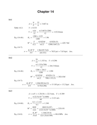
  • 1. Chapter 14 14-1 d = N P = 22 6 = 3.667 in Table 14-2: Y = 0.331 V = πdn 12 = π(3.667)(1200) 12 = 1152 ft/min Eq. (14-4b): Kv = 1200 + 1152 1200 = 1.96 Wt = T d/2 = 63 025H nd/2 = 63 025(15) 1200(3.667/2) = 429.7 lbf Eq. (14-7): σ = KvWt P FY = 1.96(429.7)(6) 2(0.331) = 7633 psi = 7.63 kpsi Ans. 14-2 d = 16 12 = 1.333 in, Y = 0.296 V = π(1.333)(700) 12 = 244.3 ft/min Eq. (14-4b): Kv = 1200 + 244.3 1200 = 1.204 Wt = 63 025H nd/2 = 63 025(1.5) 700(1.333/2) = 202.6 lbf Eq. (14-7): σ = KvWt P FY = 1.204(202.6)(12) 0.75(0.296) = 13 185 psi = 13.2 kpsi Ans. 14-3 d = mN = 1.25(18) = 22.5 mm, Y = 0.309 V = π(22.5)(10−3 )(1800) 60 = 2.121 m/s Eq. (14-6b): Kv = 6.1 + 2.121 6.1 = 1.348 Wt = 60H πdn = 60(0.5)(103 ) π(22.5)(10−3)(1800) = 235.8 N Eq. (14-8): σ = KvWt FmY = 1.348(235.8) 12(1.25)(0.309) = 68.6 MPa Ans. shi20396_ch14.qxd 8/20/03 12:43 PM Page 360
  • 2. Chapter 14 361 14-4 d = 5(15) = 75 mm, Y = 0.290 V = π(75)(10−3 )(200) 60 = 0.7854 m/s Assume steel and apply Eq. (14-6b): Kv = 6.1 + 0.7854 6.1 = 1.129 Wt = 60H πdn = 60(5)(103 ) π(75)(10−3)(200) = 6366 N Eq. (14-8): σ = KvWt FmY = 1.129(6366) 60(5)(0.290) = 82.6 MPa Ans. 14-5 d = 1(16) = 16 mm, Y = 0.296 V = π(16)(10−3 )(400) 60 = 0.335 m/s Assume steel and apply Eq. (14-6b): Kv = 6.1 + 0.335 6.1 = 1.055 Wt = 60H πdn = 60(0.15)(103 ) π(16)(10−3)(400) = 447.6 N Eq. (14-8): F = KvWt σmY = 1.055(447.6) 150(1)(0.296) = 10.6 mm From Table A-17, use F = 11 mm Ans. 14-6 d = 1.5(17) = 25.5 mm, Y = 0.303 V = π(25.5)(10−3 )(400) 60 = 0.534 m/s Eq. (14-6b): Kv = 6.1 + 0.534 6.1 = 1.088 Wt = 60H πdn = 60(0.25)(103 ) π(25.5)(10−3)(400) = 468 N Eq. (14-8): F = KvWt σmY = 1.088(468) 75(1.5)(0.303) = 14.9 mm Use F = 15 mm Ans. shi20396_ch14.qxd 8/20/03 12:43 PM Page 361
  • 3. 362 Solutions Manual • Instructor’s Solution Manual to Accompany Mechanical Engineering Design 14-7 d = 24 5 = 4.8 in, Y = 0.337 V = π(4.8)(50) 12 = 62.83 ft/min Eq. (14-4b): Kv = 1200 + 62.83 1200 = 1.052 Wt = 63 025H nd/2 = 63 025(6) 50(4.8/2) = 3151 lbf Eq. (14-7): F = KvWt P σY = 1.052(3151)(5) 20(103)(0.337) = 2.46 in Use F = 2.5 in Ans. 14-8 d = 16 5 = 3.2 in, Y = 0.296 V = π(3.2)(600) 12 = 502.7 ft/min Eq. (14-4b): Kv = 1200 + 502.7 1200 = 1.419 Wt = 63 025(15) 600(3.2/2) = 984.8 lbf Eq. (14-7): F = KvWt P σY = 1.419(984.8)(5) 10(103)(0.296) = 2.38 in Use F = 2.5 in Ans. 14-9 Try P = 8 which gives d = 18/8 = 2.25 in and Y = 0.309. V = π(2.25)(600) 12 = 353.4 ft/min Eq. (14-4b): Kv = 1200 + 353.4 1200 = 1.295 Wt = 63 025(2.5) 600(2.25/2) = 233.4 lbf Eq. (14-7): F = KvWt P σY = 1.295(233.4)(8) 10(103)(0.309) = 0.783 in shi20396_ch14.qxd 8/20/03 12:43 PM Page 362
  • 4. Chapter 14 363 Using coarse integer pitches from Table 13-2, the following table is formed. P d V Kv Wt F 2 9.000 1413.717 2.178 58.356 0.082 3 6.000 942.478 1.785 87.535 0.152 4 4.500 706.858 1.589 116.713 0.240 6 3.000 471.239 1.393 175.069 0.473 8 2.250 353.429 1.295 233.426 0.782 10 1.800 282.743 1.236 291.782 1.167 12 1.500 235.619 1.196 350.139 1.627 16 1.125 176.715 1.147 466.852 2.773 Other considerations may dictate the selection. Good candidates are P = 8 (F = 7/8 in) and P = 10 (F = 1.25 in). Ans. 14-10 Try m = 2 mm which gives d = 2(18) = 36 mm and Y = 0.309. V = π(36)(10−3 )(900) 60 = 1.696 m/s Eq. (14-6b): Kv = 6.1 + 1.696 6.1 = 1.278 Wt = 60(1.5)(103 ) π(36)(10−3)(900) = 884 N Eq. (14-8): F = 1.278(884) 75(2)(0.309) = 24.4 mm Using the preferred module sizes from Table 13-2: m d V Kv Wt F 1.00 18.0 0.848 1.139 1768.388 86.917 1.25 22.5 1.060 1.174 1414.711 57.324 1.50 27.0 1.272 1.209 1178.926 40.987 2.00 36.0 1.696 1.278 884.194 24.382 3.00 54.0 2.545 1.417 589.463 12.015 4.00 72.0 3.393 1.556 442.097 7.422 5.00 90.0 4.241 1.695 353.678 5.174 6.00 108.0 5.089 1.834 294.731 3.888 8.00 144.0 6.786 2.112 221.049 2.519 10.00 180.0 8.482 2.391 176.839 1.824 12.00 216.0 10.179 2.669 147.366 1.414 16.00 288.0 13.572 3.225 110.524 0.961 20.00 360.0 16.965 3.781 88.419 0.721 25.00 450.0 21.206 4.476 70.736 0.547 32.00 576.0 27.143 5.450 55.262 0.406 40.00 720.0 33.929 6.562 44.210 0.313 50.00 900.0 42.412 7.953 35.368 0.243 Other design considerations may dictate the size selection. For the present design, m = 2 mm (F = 25 mm) is a good selection. Ans. shi20396_ch14.qxd 8/20/03 12:43 PM Page 363
  • 5. 364 Solutions Manual • Instructor’s Solution Manual to Accompany Mechanical Engineering Design 14-11 dP = 22 6 = 3.667 in, dG = 60 6 = 10 in V = π(3.667)(1200) 12 = 1152 ft/min Eq. (14-4b): Kv = 1200 + 1152 1200 = 1.96 Wt = 63 025(15) 1200(3.667/2) = 429.7 lbf Table 14-8: Cp = 2100 psi Eq. (14-12): r1 = 3.667 sin 20° 2 = 0.627 in, r2 = 10 sin 20° 2 = 1.710 in Eq. (14-14): σC = −Cp KvWt F cos φ 1 r1 + 1 r2 1/2 = −2100 1.96(429.7) 2 cos 20° 1 0.627 + 1 1.710 1/2 = −65.6(103 ) psi = −65.6 kpsi Ans. 14-12 dP = 16 12 = 1.333 in, dG = 48 12 = 4 in V = π(1.333)(700) 12 = 244.3 ft/min Eq. (14-4b): Kv = 1200 + 244.3 1200 = 1.204 Wt = 63 025(1.5) 700(1.333/2) = 202.6 lbf Table 14-8: Cp = 2100 √ psi Eq. (14-12): r1 = 1.333 sin 20° 2 = 0.228 in, r2 = 4 sin 20° 2 = 0.684 in Eq. (14-14): σC = −2100 1.202(202.6) F cos 20° 1 0.228 + 1 0.684 1/2 = −100(103 ) F = 2100 100(103) 2 1.202(202.6) cos 20° 1 0.228 + 1 0.684 = 0.668 in Use F = 0.75 in Ans. shi20396_ch14.qxd 8/20/03 12:43 PM Page 364
  • 6. Chapter 14 365 14-13 dP = 24 5 = 4.8 in, dG = 48 5 = 9.6 in Eq. (14-4a): V = π(4.8)(50) 12 = 62.83 ft/min Kv = 600 + 62.83 600 = 1.105 Wt = 63 025H 50(4.8/2) = 525.2H Table 14-8: Cp = 1960 √ psi Eq. (14-12): r1 = 4.8 sin 20◦ 2 = 0.821 in, r2 = 2r1 = 1.642 in Eq. (14-14): −100(103 ) = −1960 1.105(525.2H) 2.5 cos 20◦ 1 0.821 + 1 1.642 1/2 H = 5.77 hp Ans. 14-14 dP = 4(20) = 80 mm, dG = 4(32) = 128 mm V = π(80)(10−3 )(1000) 60 = 4.189 m/s Kv = 3.05 + 4.189 3.05 = 2.373 Wt = 60(10)(103 ) π(80)(10−3)(1000) = 2387 N Cp = 163 √ MPa r1 = 80 sin 20° 2 = 13.68 mm, r2 = 128 sin 20° 2 = 21.89 mm σC = −163 2.373(2387) 50 cos 20° 1 13.68 + 1 21.89 1/2 = −617 MPa Ans. 14-15 The pinion controls the design. Bending YP = 0.303, YG = 0.359 dP = 17 12 = 1.417 in, dG = 30 12 = 2.500 in V = πdPn 12 = π(1.417)(525) 12 = 194.8 ft/min Eq. (14-4b): Kv = 1200 + 194.8 1200 = 1.162 Eq. (7-8): Se = 0.504(76) = 38 300 psi Eq. (7-18): ka = 2.70(76)−0.265 = 0.857 Eq. (14-6a): Table 14-8: Eq. (14-12): Eq. (14-14): shi20396_ch14.qxd 8/20/03 12:43 PM Page 365
  • 7. 366 Solutions Manual • Instructor’s Solution Manual to Accompany Mechanical Engineering Design l = 2.25 Pd = 2.25 12 = 0.1875 in x = 3YP 2P = 3(0.303) 2(12) = 0.0379 in t = 4(0.1875)(0.0379) = 0.1686 in de = 0.808 0.875(0.1686) = 0.310 in kb = 0.310 0.30 −0.107 = 0.996 kc = kd = ke = 1, kf1 = 1.65 rf = 0.300 12 = 0.025 in r d = rf t = 0.025 0.1686 = 0.148 Approximate D/d = ∞ with D/d = 3; from Fig. A-15-6, Kt = 1.68. Eq. (7-35): Kf = 1.68 1 + 2 √ 0.025 1.68 − 1 1.68 4 76 = 1.323 Miscellaneous-Effects Factor: kf = kf 1kf 2 = 1.65 1 1.323 = 1.247 Se = 0.857(0.996)(1)(1)(1)(1.247)(38 300) = 40 770 psi σall = 40 770 2.25 = 18 120 psi Wt = FYPσall Kv Pd = 0.875(0.303)(18 120) 1.162(12) = 345 lbf H = 345(194.8) 33 000 = 2.04 hp Ans. Wear ν1 = ν2 = 0.292, E1 = E2 = 30(106 ) psi Eq. (14-14): Cp = 2300 psi r1 = dP 2 sin φ = 1.417 2 sin 20° = 0.242 in r2 = dG 2 sin φ = 2.500 2 sin 20° = 0.428 1 r1 + 1 r2 = 1 0.242 + 1 0.428 = 6.469 in−1 Eq. (14-12): Eq. (7-17): Eq. (14-3): Eq. (7-24): Eq. (7-19): shi20396_ch14.qxd 8/20/03 12:43 PM Page 366
  • 8. Chapter 14 367 From Eq. (7-68), (SC)108 = 0.4HB − 10 kpsi = [0.4(149) − 10](103 ) = 49 600 psi σC,all = −49 600 √ 2.25 = −33 067 psi Wt = −33 067 2300 2 0.875 cos 20° 1.162(6.469) = 22.6 lbf H = 22.6(194.8) 33 000 = 0.133 hp Ans. Rating power (pinion controls): H1 = 2.04 hp H2 = 0.133 hp Hall = (min 2.04, 0.133) = 0.133 hp Ans. 14-16 Pinion controls: YP = 0.322, YG = 0.447 Bending dP = 20/3 = 6.667 in, dG = 33.333 in V = πdPn/12 = π(6.667)(870)/12 = 1519 ft/min Kv = (1200 + 1519)/1200 = 2.266 Se = 0.504(113) = 56.950 kpsi = 56 950 psi ka = 2.70(113)−0.265 = 0.771 l = 2.25/Pd = 2.25/3 = 0.75 in x = 3(0.322)/[2(3)] = 0.161 in t = 4(0.75)(0.161) = 0.695 in de = 0.808 2.5(0.695) = 1.065 in kb = (1.065/0.30)−0.107 = 0.873 kc = kd = ke = 1 rf = 0.300/3 = 0.100 in r d = rf t = 0.100 0.695 = 0.144 From Table A-15-6, Kt = 1.75; Eq. (7-35): Kf = 1.597 kf 2 = 1/1.597, kf = kf 1kf 2 = 1.65/1.597 = 1.033 Se = 0.771(0.873)(1)(1)(1)(1.033)(56 950) = 39 600 psi σall = 39 600/1.5 = 26 400 psi Wt = FYPσall Kv Pd = 2.5(0.322)(26 400) 2.266(3) = 3126 lbf H = Wt V/33 000 = 3126(1519)/33 000 = 144 hp Ans. shi20396_ch14.qxd 8/20/03 12:43 PM Page 367
  • 9. 368 Solutions Manual • Instructor’s Solution Manual to Accompany Mechanical Engineering Design Wear Cp = 2300 psi r1 = (6.667/2) sin 20° = 1.140 in r2 = (33.333/2) sin 20° = 5.700 in SC = [0.4(262) − 10](103 ) = 94 800 psi σC,all = −SC/ √ nd = −94.800/ √ 1.5 = −77 404 psi Wt = σC,all Cp 2 F cos φ Kv 1 1/r1 + 1/r2 = −77 404 2300 2 2.5 cos 20° 2.266 1 1/1.140 + 1/5.700 = 1115 lbf H = Wt V 33 000 = 1115(1519) 33 000 = 51.3 hp Ans. For 108 cycles (revolutions of the pinion), the power based on wear is 51.3 hp. Rating power–pinion controls H1 = 144 hp H2 = 51.3 hp Hrated = min(144, 51.3) = 51.3 hp Ans. 14-17 Given: φ = 20°, n = 1145 rev/min, m = 6 mm, F = 75 mm, NP = 16 milled teeth, NG = 30T, Sut = 900 MPa, HB = 260, nd = 3, YP = 0.296, and YG = 0.359. Pinion bending dP = mNP = 6(16) = 96 mm dG = 6(30) = 180 mm V = πdPn 12 = π(96)(1145)(10−3 )(12) (12)(60) = 5.76 m/s Eq. (14-6b): Kv = 6.1 + 5.76 6.1 = 1.944 Se = 0.504(900) = 453.6 MPa a = 4.45, b = −0.265 ka = 4.51(900)−0.265 = 0.744 l = 2.25m = 2.25(6) = 13.5 mm x = 3Ym/2 = 3(0.296)6/2 = 2.664 mm t = √ 4lx = 4(13.5)(2.664) = 12.0 mm de = 0.808 75(12.0) = 24.23 mm Table 14-8: Eq. (14-12): Eq. (7-68): shi20396_ch14.qxd 8/20/03 12:43 PM Page 368
  • 10. Chapter 14 369 kb = 24.23 7.62 −0.107 = 0.884 kc = kd = ke = 1 rf = 0.300m = 0.300(6) = 1.8 mm From Fig. A-15-6 for r/d = rf /t = 1.8/12 = 0.15, Kt = 1.68. Kf = 1.68 1 + 2 √ 1.8 [(1.68 − 1)/1.68](139/900) = 1.537 kf 1 = 1.65 (Gerber failure criterion) kf 2 = 1/Kf = 1/1.537 = 0.651 kf = kf 1kf 2 = 1.65(0.651) = 1.074 Se = 0.744(0.884)(1)(1)(1)(1.074)(453.6) = 320.4 MPa σall = Se nd = 320.4 1.3 = 246.5 MPa Eq. (14-8): Wt = FYmσall Kv = 75(0.296)(6)(246.5) 1.944 = 16 890 N H = Tn 9.55 = 16 890(96/2)(1145) 9.55(106) = 97.2 kW Ans. Wear: Pinion and gear Eq. (14-12): r1 = (96/2) sin 20◦ = 16.42 mm r2 = (180/2) sin 20◦ = 30.78 mm Table 14-8: Cp ˙= 191 √ MPa Eq. (7-68): SC = 6.89[0.4(260) − 10] = 647.7 MPa σC,all = − 647.7 √ 1.3 = −568 MPa Eq. (14-14): Wt = σC,all Cp 2 F cos φ Kv 1 1/r1 + 1/r2 = −568 191 2 75 cos 20◦ 1.944 1 1/16.42 + 1/30.78 = 3433 N T = WtdP 2 = 3433(96) 2 = 164 784 N · mm = 164.8 N · m H = Tn 9.55 = 164.8(1145) 9.55 = 19 758.7 W = 19.8 kW Ans. Thus, wear controls the gearset power rating; H = 19.8 kW. Ans. shi20396_ch14.qxd 8/20/03 12:43 PM Page 369
  • 11. 370 Solutions Manual • Instructor’s Solution Manual to Accompany Mechanical Engineering Design 14-18 Preliminaries: NP = 17, NG = 51 dP = N Pd = 17 6 = 2.833 in dG = 51 6 = 8.500 in V = πdPn/12 = π(2.833)(1120)/12 = 830.7 ft/min Eq. (14-4b): Kv = (1200 + 830.7)/1200 = 1.692 σall = Sy nd = 90 000 2 = 45 000 psi Table 14-2: YP = 0.303, YG = 0.410 Eq. (14-7): Wt = FYPσall Kv Pd = 2(0.303)(45 000) 1.692(6) = 2686 lbf H = WtV 33 000 = 2686(830.7) 33 000 = 67.6 hp Based on yielding in bending, the power is 67.6 hp. (a) Pinion fatigue Bending Se = 0.504(232/2) = 58 464 psi a = 2.70, b = −0.265, ka = 2.70(116)−0.265 = 0.766 Table 13-1: l = 1 Pd + 1.25 Pd = 2.25 Pd = 2.25 6 = 0.375 in Eq. (14-3): x = 3YP 2Pd = 3(0.303) 2(6) = 0.0758 t = √ 4lx = 4(0.375)(0.0758) = 0.337 in de = 0.808 √ Ft = 0.808 2(0.337) = 0.663 in kb = 0.663 0.30 −0.107 = 0.919 kc = kd = ke = 1. Assess two components contributing to kf . First, based upon one-way bending and the Gerber failure criterion, kf 1 = 1.65. Second, due to stress- concentration, rf = 0.300 Pd = 0.300 6 = 0.050 in Fig. A-15-6: r d = rf t = 0.05 0.338 = 0.148 shi20396_ch14.qxd 8/20/03 12:43 PM Page 370
  • 12. Chapter 14 371 Estimate D/d = ∞ by setting D/d = 3, Kt = 1.68. From Eq. (7-35) and Table 7-8, Kf = 1.68 1 + 2 √ 0.05 [(1.68 − 1)/1.68](4/116) = 1.494 kf 2 = 1 Kf = 1 1.494 = 0.669 kf = kf 1kf 2 = 1.65(0.669) = 1.104 Se = 0.766(0.919)(1)(1)(1)(1.104)(58 464) = 45 436 psi σall = Se nd = 45 436 2 = 22 718 psi Wt = FYPσall Kv Pd = 2(0.303)(22 718) 1.692(6) = 1356 lbf H = Wt V 33 000 = 1356(830.7) 33 000 = 34.1 hp Ans. (b) Pinion fatigue Wear From Table A-5 for steel: ν = 0.292, E = 30(106 ) psi Eq. (14-13) or Table 14-8: Cp = 1 2π[(1 − 0.2922)/30(106)] 1/2 = 2285 psi In preparation for Eq. (14-14): Eq. (14-12): r1 = dP 2 sin φ = 2.833 2 sin 20◦ = 0.485 in r2 = dG 2 sin φ = 8.500 2 sin 20◦ = 1.454 in 1 r1 + 1 r2 = 1 0.485 + 1 1.454 = 2.750 in Eq. (7-68): (SC)108 = 0.4HB − 10 kpsi In terms of gear notation σC = [0.4(232) − 10]103 = 82 800 psi We will introduce the design factor of nd = 2 and apply it to the load Wt by dividing by √ 2. σC,all = − σc √ 2 = − 82 800 √ 2 = −58 548 psi shi20396_ch14.qxd 8/20/03 12:43 PM Page 371
  • 13. 372 Solutions Manual • Instructor’s Solution Manual to Accompany Mechanical Engineering Design Solve Eq. (14-14) for Wt : Wt = −58 548 2285 2 2 cos 20◦ 1.692(2.750) = 265 lbf Hall = 265(830.7) 33 000 = 6.67 hp Ans. For 108 cycles (turns of pinion), the allowable power is 6.67 hp. (c) Gear fatigue due to bending and wear Bending Eq. (14-3): x = 3YG 2Pd = 3(0.4103) 2(6) = 0.1026 in t = 4(0.375)(0.1026) = 0.392 in de = 0.808 2(0.392) = 0.715 in kb = 0.715 0.30 −0.107 = 0.911 kc = kd = ke = 1 r d = rf t = 0.050 0.392 = 0.128 Approximate D/d = ∞ by setting D/d = 3 for Fig. A-15-6; Kt = 1.80. Use Kf = 1.583. kf 2 = 1 1.583 = 0.632, kf = 1.65(0.632) = 1.043 Se = 0.766(0.911)(1)(1)(1)(1.043)(58 464) = 42 550 psi σall = Se 2 = 42 550 2 = 21 275 psi Wt = 2(0.4103)(21 275) 1.692(6) = 1720 lbf Hall = 1720(830.7) 33 000 = 43.3 hp Ans. The gear is thus stronger than the pinion in bending. Wear Since the material of the pinion and the gear are the same, and the contact stresses are the same, the allowable power transmission of both is the same. Thus, Hall = 6.67 hp for 108 revolutions of each. As yet, we have no way to establish SC for 108 /3 revolutions. shi20396_ch14.qxd 8/20/03 12:43 PM Page 372
  • 14. Chapter 14 373 (d) Pinion bending: H1 = 34.1 hp Pinion wear: H2 = 6.67 hp Gear bending: H3 = 43.3 hp Gear wear: H4 = 6.67 hp Power rating of the gear set is thus Hrated = min(34.1, 6.67, 43.3, 6.67) = 6.67 hp Ans. 14-19 dP = 16/6 = 2.667 in, dG = 48/6 = 8 in V = π(2.667)(300) 12 = 209.4 ft/min Wt = 33 000(5) 209.4 = 787.8 lbf Assuming uniform loading, Ko = 1. From Eq. (14-28), Qv = 6, B = 0.25(12 − 6)2/3 = 0.8255 A = 50 + 56(1 − 0.8255) = 59.77 Eq. (14-27): Kv = 59.77 + √ 209.4 59.77 0.8255 = 1.196 From Table 14-2, NP = 16T, YP = 0.296 NG = 48T, YG = 0.4056 From Eq. (a), Sec. 14-10 with F = 2 in (Ks)P = 1.192 2 √ 0.296 6 0.0535 = 1.088 (Ks)G = 1.192 2 √ 0.4056 6 0.0535 = 1.097 From Eq. (14-30) with Cmc = 1 Cpf = 2 10(2.667) − 0.0375 + 0.0125(2) = 0.0625 Cpm = 1, Cma = 0.093 (Fig. 14-11), Ce = 1 Km = 1 + 1[0.0625(1) + 0.093(1)] = 1.156 Assuming constant thickness of the gears → KB = 1 mG = NG/NP = 48/16 = 3 With N (pinion) = 108 cycles and N (gear) = 108 /3, Fig. 14-14 provides the relations: (YN )P = 1.3558(108 )−0.0178 = 0.977 (YN )G = 1.3558(108 /3)−0.0178 = 0.996 shi20396_ch14.qxd 8/20/03 12:43 PM Page 373
  • 15. 374 Solutions Manual • Instructor’s Solution Manual to Accompany Mechanical Engineering Design Fig. 14-6: JP = 0.27, JG ˙= 0.38 From Table 14-10 for R = 0.9, KR = 0.85 KT = Cf = 1 Eq. (14-23) with mN = 1 I = cos 20◦ sin 20◦ 2 3 3 + 1 = 0.1205 Table 14-8: Cp = 2300 psi Strength: Grade 1 steel with HBP = HBG = 200 Fig. 14-2: (St)P = (St)G = 77.3(200) + 12 800 = 28 260 psi Fig. 14-5: (Sc)P = (Sc)G = 322(200) + 29 100 = 93 500 psi Fig. 14-15: (ZN )P = 1.4488(108 )−0.023 = 0.948 (ZN )G = 1.4488(108 /3)−0.023 = 0.973 Sec. 14-12: HBP/HBG = 1 ∴ CH = 1 Pinion tooth bending Eq. (14-15): (σ)P = Wt KoKv Ks Pd F Km KB J = 787.8(1)(1.196)(1.088) 6 2 (1.156)(1) 0.27 = 13 167 psi Ans. Factor of safety from Eq. (14-41) (SF)P = StYN /(KT KR) σ = 28 260(0.977)/[(1)(0.85)] 13 167 = 2.47 Ans. Gear tooth bending (σ)G = 787.8(1)(1.196)(1.097) 6 2 (1.156)(1) 0.38 = 9433 psi Ans. (SF)G = 28 260(0.996)/[(1)(0.85)] 9433 = 3.51 Ans. Pinion tooth wear Eq. (14-16): (σc)P = Cp Wt KoKv Ks Km dP F Cf I 1/2 P = 2300 787.8(1)(1.196)(1.088) 1.156 2.667(2) 1 0.1205 1/2 = 98 760 psi Ans. Eq. (14-42): (SH )P = Sc ZN /(KT KR) σc P = 93 500(0.948)/[(1)(0.85)] 98 760 = 1.06 Ans. shi20396_ch14.qxd 8/20/03 12:43 PM Page 374
  • 16. Chapter 14 375 Gear tooth wear (σc)G = (Ks)G (Ks)P 1/2 (σc)P = 1.097 1.088 1/2 (98 760) = 99 170 psi Ans. (SH )G = 93 500(0.973)(1)/[(1)(0.85)] 99 170 = 1.08 Ans. The hardness of the pinion and the gear should be increased. 14-20 dP = 2.5(20) = 50 mm, dG = 2.5(36) = 90 mm V = πdPnP 60 = π(50)(10−3 )(100) 60 = 0.2618 m/s Wt = 60(120) π(50)(10−3)(100) = 458.4 N Eq. (14-28): Ko = 1, Qv = 6, B = 0.25(12 − 6)2/3 = 0.8255 A = 50 + 56(1 − 0.8255) = 59.77 Eq. (14-27): Kv = 59.77 + √ 200(0.2618) 59.77 0.8255 = 1.099 Table 14-2: YP = 0.322, YG = 0.3775 Similar to Eq. (a) of Sec. 14-10 but for SI units: Ks = 1 kb = 0.8433 mF √ Y 0.0535 (Ks)P = 0.8433 2.5(18) √ 0.322 0.0535 = 1.003 use 1 (Ks)G = 0.8433 2.5(18) √ 0.3775 0.0535 > 1 use 1 Cmc = 1, F = 18/25.4 = 0.709 in, Cpf = 18 10(50) − 0.025 = 0.011 Cpm = 1, Cma = 0.247 + 0.0167(0.709) − 0.765(10−4 )(0.7092 ) = 0.259 Ce = 1 KH = 1 + 1[0.011(1) + 0.259(1)] = 1.27 Eq. (14-40): KB = 1, mG = NG/NP = 36/20 = 1.8 Fig. 14-14: (YN )P = 1.3558(108 )−0.0178 = 0.977 (YN )G = 1.3558(108 /1.8)−0.0178 = 0.987 Fig. 14-6: (YJ )P = 0.33, (YJ )G = 0.38 Eq. (14-38): YZ = 0.658 − 0.0759 ln(1 − 0.95) = 0.885 Yθ = ZR = 1 shi20396_ch14.qxd 8/20/03 12:43 PM Page 375
  • 17. 376 Solutions Manual • Instructor’s Solution Manual to Accompany Mechanical Engineering Design Eq. (14-23) with mN = 1: ZI = cos 20◦ sin 20◦ 2 1.8 1.8 + 1 = 0.103 Table 14-8: ZE = 191 √ MPa Strength Grade 1 steel, HBP = HBG = 200 Fig. 14-2: (σF P)P = (σF P)G = 0.533(200) + 88.3 = 194.9 MPa Fig. 14-5: (σH P)P = (σH P)G = 2.22(200) + 200 = 644 MPa Fig. 14-15: (ZN )P = 1.4488(108 )−0.023 = 0.948 (ZN )G = 1.4488(108 /1.8)−0.023 = 0.961 HBP/HBG = 1 ∴ ZW = 1 Pinion tooth bending (σ)P = Wt KoKv Ks 1 bmt KH KB YJ P = 458.4(1)(1.099)(1) 1 18(2.5) 1.27(1) 0.33 = 43.08 MPa Ans. (SF)P = σF P σ YN Yθ YZ P = 194.9 43.08 0.977 1(0.885) = 4.99 Ans. Gear tooth bending (σ)G = 458.4(1)(1.099)(1) 1 18(2.5) 1.27(1) 0.38 = 37.42 MPa Ans. (SF)G = 194.9 37.42 0.987 1(0.885) = 5.81 Ans. Pinion tooth wear (σc)P = ZE Wt KoKv Ks KH dw1b ZR ZI P = 191 458.4(1)(1.099)(1) 1.27 50(18) 1 0.103 = 501.8 MPa Ans. (SH )P = σH P σc ZN ZW Yθ YZ P = 644 501.8 0.948(1) 1(0.885) = 1.37 Ans. Gear tooth wear (σc)G = (Ks)G (Ks)P 1/2 (σc)P = 1 1 1/2 (501.8) = 501.8 MPa Ans. (SH )G = 644 501.8 0.961(1) 1(0.885) = 1.39 Ans. shi20396_ch14.qxd 8/20/03 12:43 PM Page 376
  • 18. Chapter 14 377 14-21 Pt = Pn cos ψ = 6 cos 30° = 5.196 teeth/in dP = 16 5.196 = 3.079 in, dG = 48 16 (3.079) = 9.238 in V = π(3.079)(300) 12 = 241.8 ft/min Wt = 33 000(5) 241.8 = 682.3 lbf, Kv = 59.77 + √ 241.8 59.77 0.8255 = 1.210 From Prob. 14-19: YP = 0.296, YG = 0.4056 (Ks)P = 1.088, (Ks)G = 1.097, KB = 1 mG = 3, (YN )P = 0.977, (YN )G = 0.996, KR = 0.85 (St)P = (St)G = 28 260 psi, CH = 1, (Sc)P = (Sc)G = 93 500 psi (ZN )P = 0.948, (ZN )G = 0.973, Cp = 2300 √ psi The pressure angle is: φt = tan−1 tan 20° cos 30° = 22.80° (rb)P = 3.079 2 cos 22.8° = 1.419 in, (rb)G = 3(rb)P = 4.258 in a = 1/Pn = 1/6 = 0.167 in Eq. (14-26): Z = 3.079 2 + 0.167 2 − 1.4192 1/2 + 9.238 2 + 0.167 2 − 4.2582 1/2 − 3.079 2 + 9.238 2 sin 22.8° = 0.9479 + 2.1852 − 2.3865 = 0.7466 Conditions O.K. for use pN = pn cos φn = π 6 cos 20° = 0.4920 in Eq. (14-23): mN = pN 0.95Z = 0.492 0.95(0.7466) = 0.6937 Eq. (14-23): I = sin 22.8° cos 22.8° 2(0.6937) 3 3 + 1 = 0.193 Fig. 14-7: JP ˙= 0.45, JG ˙= 0.54 shi20396_ch14.qxd 8/20/03 12:43 PM Page 377
  • 19. 378 Solutions Manual • Instructor’s Solution Manual to Accompany Mechanical Engineering Design Fig. 14-8: Corrections are 0.94 and 0.98 JP = 0.45(0.94) = 0.423, JG = 0.54(0.98) = 0.529 Cmc = 1, Cpf = 2 10(3.079) − 0.0375 + 0.0125(2) = 0.0525 Cpm = 1, Cma = 0.093, Ce = 1 Km = 1 + (1)[0.0525(1) + 0.093(1)] = 1.146 Pinion tooth bending (σ)P = 682.3(1)(1.21)(1.088) 5.196 2 1.146(1) 0.423 = 6323 psi Ans. (SF)P = 28 260(0.977)/[1(0.85)] 6323 = 5.14 Ans. Gear tooth bending (σ)G = 682.3(1)(1.21)(1.097) 5.196 2 1.146(1) 0.529 = 5097 psi Ans. (SF)G = 28 260(0.996)/[1(0.85)] 5097 = 6.50 Ans. Pinion tooth wear (σc)P = 2300 682.3(1)(1.21)(1.088) 1.146 3.078(2) 1 0.193 1/2 = 67 700 psi Ans. (SH )P = 93 500(0.948)/[(1)(0.85)] 67 700 = 1.54 Ans. Gear tooth wear (σc)G = 1.097 1.088 1/2 (67 700) = 67 980 psi Ans. (SH )G = 93 500(0.973)/[(1)(0.85)] 67 980 = 1.57 Ans. 14-22 Given: R = 0.99 at 108 cycles, HB = 232 through-hardening Grade 1, core and case, both gears. NP = 17T, NG = 51T, YP = 0.303, YG = 0.4103, JP = 0.292, JG = 0.396, dP = 2.833 in, dG = 8.500 in. Pinion bending From Fig. 14-2: 0.99(St)107 = 77.3HB + 12 800 = 77.3(232) + 12 800 = 30 734 psi shi20396_ch14.qxd 8/20/03 12:43 PM Page 378
  • 20. Chapter 14 379 Fig. 14-14: YN = 1.6831(108 )−0.0323 = 0.928 V = πdPn/12 = π(2.833)(1120/12) = 830.7 ft/min KT = KR = 1, SF = 2, SH = √ 2 σall = 30 734(0.928) 2(1)(1) = 14 261 psi Qv = 5, B = 0.25(12 − 5)2/3 = 0.9148 A = 50 + 56(1 − 0.9148) = 54.77 Kv = 54.77 + √ 830.7 54.77 0.9148 = 1.472 Ks = 1.192 2 √ 0.303 6 0.0535 = 1.089 ⇒ use 1 Km = Cm f = 1 + Cmc(Cpf Cpm + CmaCe) Cmc = 1 Cpf = F 10d − 0.0375 + 0.0125F = 2 10(2.833) − 0.0375 + 0.0125(2) = 0.0581 Cpm = 1 Cma = 0.127 + 0.0158(2) − 0.093(10−4 )(22 ) = 0.1586 Ce = 1 Km = 1 + 1[0.0581(1) + 0.1586(1)] = 1.2167 Eq. (14-15): Kβ = 1 Wt = F JPσall KoKv Ks Pd Km Kβ = 2(0.292)(14 261) 1(1.472)(1)(6)(1.2167)(1) = 775 lbf H = Wt V 33 000 = 775(830.7) 33 000 = 19.5 hp Pinion wear Fig. 14-15: ZN = 2.466N−0.056 = 2.466(108 )−0.056 = 0.879 MG = 51/17 = 3 I = sin 20◦ cos 20◦ 2 3 3 + 1 = 1.205, CH = 1 shi20396_ch14.qxd 8/20/03 12:43 PM Page 379
  • 21. 380 Solutions Manual • Instructor’s Solution Manual to Accompany Mechanical Engineering Design Fig. 14-5: 0.99(Sc)107 = 322HB + 29 100 = 322(232) + 29 100 = 103 804 psi σc,all = 103 804(0.879) √ 2(1)(1) = 64 519 psi Eq. (14-16): Wt = σc,all Cp 2 FdP I KoKv Ks KmCf = 64 519 2300 2 2(2.833)(0.1205) 1(1.472)(1)(1.2167)(1) = 300 lbf H = Wt V 33 000 = 300(830.7) 33 000 = 7.55 hp The pinion controls therefore Hrated = 7.55 hp Ans. 4-23 l = 2.25/Pd, x = 3Y 2Pd t = √ 4lx = 4 2.25 Pd 3Y 2Pd = 3.674 Pd √ Y de = 0.808 √ Ft = 0.808 F 3.674 Pd √ Y = 1.5487 F √ Y Pd kb =   1.5487 F √ Y/Pd 0.30   −0.107 = 0.8389 F √ Y Pd −0.0535 Ks = 1 kb = 1.192 F √ Y Pd 0.0535 Ans. 14-24 YP = 0.331, YG = 0.422, JP = 0.345, JG = 0.410, Ko = 1.25. The service conditions are adequately described by Ko. Set SF = SH = 1. dP = 22/4 = 5.500 in dG = 60/4 = 15.000 in V = π(5.5)(1145) 12 = 1649 ft/min Pinion bending 0.99(St)107 = 77.3HB + 12 800 = 77.3(250) + 12 800 = 32 125 psi YN = 1.6831[3(109 )]−0.0323 = 0.832 shi20396_ch14.qxd 8/20/03 12:43 PM Page 380
  • 22. Chapter 14 381 Eq. (14-17): (σall)P = 32 125(0.832) 1(1)(1) = 26 728 psi B = 0.25(12 − 6)2/3 = 0.8255 A = 50 + 56(1 − 0.8255) = 59.77 Kv = 59.77 + √ 1649 59.77 0.8255 = 1.534 Ks = 1, Cm = 1 Cmc = F 10d − 0.0375 + 0.0125F = 3.25 10(5.5) − 0.0375 + 0.0125(3.25) = 0.0622 Cma = 0.127 + 0.0158(3.25) − 0.093(10−4 )(3.252 ) = 0.178 Ce = 1 Km = Cm f = 1 + (1)[0.0622(1) + 0.178(1)] = 1.240 Kβ = 1, KT = 1 Eq. (14-15): Wt 1 = 26 728(3.25)(0.345) 1.25(1.534)(1)(4)(1.240) = 3151 lbf H1 = 3151(1649) 33 000 = 157.5 hp Gear bending By similar reasoning, Wt 2 = 3861 lbf and H2 = 192.9 hp Pinion wear mG = 60/22 = 2.727 I = cos 20◦ sin 20◦ 2 2.727 1 + 2.727 = 0.1176 0.99(Sc)107 = 322(250) + 29 100 = 109 600 psi (ZN )P = 2.466[3(109 )]−0.056 = 0.727 (ZN )G = 2.466[3(109 )/2.727]−0.056 = 0.769 (σc,all)P = 109 600(0.727) 1(1)(1) = 79 679 psi Wt 3 = σc,all Cp 2 FdP I KoKv Ks KmCf = 79 679 2300 2 3.25(5.5)(0.1176) 1.25(1.534)(1)(1.24)(1) = 1061 lbf H3 = 1061(1649) 33 000 = 53.0 hp shi20396_ch14.qxd 8/20/03 12:43 PM Page 381
  • 23. 382 Solutions Manual • Instructor’s Solution Manual to Accompany Mechanical Engineering Design Gear wear Similarly, Wt 4 = 1182 lbf, H4 = 59.0 hp Rating Hrated = min(H1, H2, H3, H4) = min(157.5, 192.9, 53, 59) = 53 hp Ans. Note differing capacities. Can these be equalized? 14-25 From Prob. 14-24: Wt 1 = 3151 lbf, Wt 2 = 3861 lbf, Wt 3 = 1061 lbf, Wt 4 = 1182 lbf Wt = 33 000Ko H V = 33 000(1.25)(40) 1649 = 1000 lbf Pinion bending: The factor of safety, based on load and stress, is (SF)P = Wt 1 1000 = 3151 1000 = 3.15 Gear bending based on load and stress (SF)G = Wt 2 1000 = 3861 1000 = 3.86 Pinion wear based on load: n3 = Wt 3 1000 = 1061 1000 = 1.06 based on stress: (SH )P = √ 1.06 = 1.03 Gear wear based on load: n4 = Wt 4 1000 = 1182 1000 = 1.18 based on stress: (SH )G = √ 1.18 = 1.09 Factors of safety are used to assess the relative threat of loss of function 3.15, 3.86, 1.06, 1.18 where the threat is from pinion wear. By comparison, the AGMA safety factors (SF)P, (SF)G, (SH )P, (SH )G are 3.15, 3.86, 1.03, 1.09 or 3.15, 3.86, 1.061/2 , 1.181/2 and the threat is again from pinion wear. Depending on the magnitude of the numbers, using SF and SH as defined by AGMA, does not necessarily lead to the same conclusion concerning threat. Therefore be cautious. shi20396_ch14.qxd 8/20/03 12:43 PM Page 382
  • 24. Chapter 14 383 14-26 Solution summary from Prob. 14-24: n = 1145 rev/min, Ko = 1.25, Grade 1 materials, NP = 22T, NG = 60T, mG = 2.727, YP = 0.331, YG = 0.422, JP = 0.345, JG = 0.410, Pd = 4T/in, F = 3.25 in, Qv = 6, (Nc)P = 3(109 ), R = 0.99 Pinion HB: 250 core, 390 case Gear HB: 250 core, 390 case Km = 1.240, KT = 1, Kβ = 1, dP = 5.500 in, dG = 15.000 in, V = 1649 ft/min, Kv = 1.534, (Ks)P = (Ks)G = 1, (YN )P = 0.832, (YN )G = 0.859, KR = 1 Bending (σall)P = 26 728 psi (St)P = 32 125 psi (σall)G = 27 546 psi (St)G = 32 125 psi Wt 1 = 3151 lbf, H1 = 157.5 hp Wt 2 = 3861 lbf, H2 = 192.9 hp Wear φ = 20◦ , I = 0.1176, (ZN )P = 0.727, (ZN )G = 0.769, CP = 2300 psi (Sc)P = Sc = 322(390) + 29 100 = 154 680 psi (σc,all)P = 154 680(0.727) 1(1)(1) = 112 450 psi (σc,all)G = 154 680(0.769) 1(1)(1) = 118 950 psi Wt 3 = 112 450 79 679 2 (1061) = 2113 lbf, H3 = 2113(1649) 33 000 = 105.6 hp Wt 4 = 118 950 109 600(0.769) 2 (1182) = 2354 lbf, H4 = 2354(1649) 33 000 = 117.6 hp Rated power Hrated = min(157.5, 192.9, 105.6, 117.6) = 105.6 hp Ans. Prob. 14-24 Hrated = min(157.5, 192.9, 53.0, 59.0) = 53 hp The rated power approximately doubled. 14-27 The gear and the pinion are 9310 grade 1, carburized and case-hardened to obtain Brinell 285 core and Brinell 580–600 case. Table 14-3: 0.99(St)107 = 55 000 psi shi20396_ch14.qxd 8/20/03 12:43 PM Page 383
  • 25. 384 Solutions Manual • Instructor’s Solution Manual to Accompany Mechanical Engineering Design Modification of St by (YN )P = 0.832 produces (σall)P = 45 657 psi, Similarly for (YN )G = 0.859 (σall)G = 47 161 psi, and Wt 1 = 4569 lbf, H1 = 228 hp Wt 2 = 5668 lbf, H2 = 283 hp From Table 14-8, Cp = 2300 psi. Also, from Table 14-6: 0.99(Sc)107 = 180 000 psi Modification of Sc by (YN ) produces (σc,all)P = 130 525 psi (σc,all)G = 138 069 psi and Wt 3 = 2489 lbf, H3 = 124.3 hp Wt 4 = 2767 lbf, H4 = 138.2 hp Rating Hrated = min(228, 283, 124, 138) = 124 hp Ans. 14-28 Grade 2 9310 carburized and case-hardened to 285 core and 580 case in Prob. 14-27. Summary: Table 14-3: 0.99(St)107 = 65 000 psi (σall)P = 53 959 psi (σall)G = 55 736 psi and it follows that Wt 1 = 5399.5 lbf, H1 = 270 hp Wt 2 = 6699 lbf, H2 = 335 hp From Table 14-8, Cp = 2300 psi. Also, from Table 14-6: Sc = 225 000 psi (σc,all)P = 181 285 psi (σc,all)G = 191 762 psi Consequently, Wt 3 = 4801 lbf, H3 = 240 hp Wt 4 = 5337 lbf, H4 = 267 hp Rating Hrated = min(270, 335, 240, 267) = 240 hp. Ans. shi20396_ch14.qxd 8/20/03 12:43 PM Page 384
  • 26. Chapter 14 385 14-29 n = 1145 rev/min, Ko = 1.25, NP = 22T, NG = 60T, mG = 2.727, dP = 2.75 in, dG = 7.5 in, YP = 0.331, YG = 0.422, JP = 0.335, JG = 0.405, P = 8T/in, F = 1.625 in, HB = 250, case and core, both gears. Cm = 1, F/dP = 0.0591, Cf = 0.0419, Cpm = 1, Cma = 0.152, Ce = 1, Km = 1.1942, KT = 1, Kβ = 1, Ks = 1, V = 824 ft/min, (YN )P = 0.8318, (YN )G = 0.859, KR = 1, I = 0.117 58 0.99(St)107 = 32 125 psi (σall)P = 26 668 psi (σall)G = 27 546 psi and it follows that Wt 1 = 879.3 lbf, H1 = 21.97 hp Wt 2 = 1098 lbf, H2 = 27.4 hp For wear Wt 3 = 304 lbf, H3 = 7.59 hp Wt 4 = 340 lbf, H4 = 8.50 hp Rating Hrated = min(21.97, 27.4, 7.59, 8.50) = 7.59 hp In Prob. 14-24, Hrated = 53 hp Thus 7.59 53.0 = 0.1432 = 1 6.98 , not 1 8 Ans. The transmitted load rating is Wt rated = min(879.3, 1098, 304, 340) = 304 lbf In Prob. 14-24 Wt rated = 1061 lbf Thus 304 1061 = 0.2865 = 1 3.49 , not 1 4 , Ans. 14-30 SP = SH = 1, Pd = 4, JP = 0.345, JG = 0.410, Ko = 1.25 Bending Table 14-4: 0.99(St)107 = 13 000 psi (σall)P = (σall)G = 13 000(1) 1(1)(1) = 13 000 psi Wt 1 = σall F JP KoKv Ks Pd Km Kβ = 13 000(3.25)(0.345) 1.25(1.534)(1)(4)(1.24)(1) = 1533 lbf H1 = 1533(1649) 33 000 = 76.6 hp Wt 2 = Wt 1 JG/JP = 1533(0.410)/0.345 = 1822 lbf H2 = H1 JG/JP = 76.6(0.410)/0.345 = 91.0 hp shi20396_ch14.qxd 8/20/03 12:43 PM Page 385
  • 27. 386 Solutions Manual • Instructor’s Solution Manual to Accompany Mechanical Engineering Design Wear Table 14-8: Cp = 1960 psi Table 14-7: 0.99(Sc)107 = 75 000 psi = (σc,all)P = (σc,all)G Wt 3 = (σc,all)P Cp 2 FdpI KoKv Ks KmCf Wt 3 = 75 000 1960 2 3.25(5.5)(0.1176) 1.25(1.534)(1)(1.24)(1) = 1295 lbf Wt 4 = Wt 3 = 1295 lbf H4 = H3 = 1295(1649) 33 000 = 64.7 hp Rating Hrated = min(76.7, 94.4, 64.7, 64.7) = 64.7 hp Ans. Notice that the balance between bending and wear power is improved due to CI’s more favorable Sc/St ratio. Also note that the life is 107 pinion revolutions which is (1/300) of 3(109 ). Longer life goals require power derating. 14-31 From Table A-24a, Eav = 11.8(106 ) For φ = 14.5◦ and HB = 156 SC = 1.4(81) 2 sin 14.5°/[11.8(106)] = 51 693 psi For φ = 20◦ SC = 1.4(112) 2 sin 20°/[11.8(106)] = 52 008 psi SC = 0.32(156) = 49.9 kpsi 14-32 Programs will vary. 14-33 (YN )P = 0.977, (YN )G = 0.996 (St)P = (St)G = 82.3(250) + 12 150 = 32 725 psi (σall)P = 32 725(0.977) 1(0.85) = 37 615 psi Wt 1 = 37 615(1.5)(0.423) 1(1.404)(1.043)(8.66)(1.208)(1) = 1558 lbf H1 = 1558(925) 33 000 = 43.7 hp shi20396_ch14.qxd 8/20/03 12:43 PM Page 386
  • 28. Chapter 14 387 (σall)G = 32 725(0.996) 1(0.85) = 38 346 psi Wt 2 = 38 346(1.5)(0.5346) 1(1.404)(1.043)(8.66)(1.208)(1) = 2007 lbf H2 = 2007(925) 33 000 = 56.3 hp (ZN )P = 0.948, (ZN )G = 0.973 Table 14-6: 0.99(Sc)107 = 150 000 psi (σc,allow)P = 150 000 0.948(1) 1(0.85) = 167 294 psi Wt 3 = 167 294 2300 2 1.963(1.5)(0.195) 1(1.404)(1.043) = 2074 lbf H3 = 2074(925) 33 000 = 58.1 hp (σc,allow)G = 0.973 0.948 (167 294) = 171 706 psi Wt 4 = 171 706 2300 2 1.963(1.5)(0.195) 1(1.404)(1.052) = 2167 lbf H4 = 2167(925) 33 000 = 60.7 hp Hrated = min(43.7, 56.3, 58.1, 60.7) = 43.7 hp Ans. Pinion bending controlling 14-34 (YN )P = 1.6831(108 )−0.0323 = 0.928 (YN )G = 1.6831(108 /3.059)−0.0323 = 0.962 Table 14-3: St = 55 000 psi (σall)P = 55 000(0.928) 1(0.85) = 60 047 psi Wt 1 = 60 047(1.5)(0.423) 1(1.404)(1.043)(8.66)(1.208)(1) = 2487 lbf H1 = 2487(925) 33 000 = 69.7 hp (σall)G = 0.962 0.928 (60 047) = 62 247 psi Wt 2 = 62 247 60 047 0.5346 0.423 (2487) = 3258 lbf H2 = 3258 2487 (69.7) = 91.3 hp shi20396_ch14.qxd 8/20/03 12:43 PM Page 387
  • 29. 388 Solutions Manual • Instructor’s Solution Manual to Accompany Mechanical Engineering Design Table 14-6: Sc = 180 000 psi (ZN )P = 2.466(108 )−0.056 = 0.8790 (ZN )G = 2.466(108 /3.059)−0.056 = 0.9358 (σc,all)P = 180 000(0.8790) 1(0.85) = 186 141 psi Wt 3 = 186 141 2300 2 1.963(1.5)(0.195) 1(1.404)(1.043) = 2568 lbf H3 = 2568(925) 33 000 = 72.0 hp (σc,all)G = 0.9358 0.8790 (186 141) = 198 169 psi Wt 4 = 198 169 186 141 2 1.043 1.052 (2568) = 2886 lbf H4 = 2886(925) 33 000 = 80.9 hp Hrated = min(69.7, 91.3, 72, 80.9) = 69.7 hp Ans. Pinion bending controlling 14-35 (YN )P = 0.928, (YN )G = 0.962 (See Prob. 14-34) Table 14-3: St = 65 000 psi (σall)P = 65 000(0.928) 1(0.85) = 70 965 psi Wt 1 = 70 965(1.5)(0.423) 1(1.404)(1.043)(8.66)(1.208) = 2939 lbf H1 = 2939(925) 33 000 = 82.4 hp (σall)G = 65 000(0.962) 1(0.85) = 73 565 psi Wt 2 = 73 565 70 965 0.5346 0.423 (2939) = 3850 lbf H2 = 3850 2939 (82.4) = 108 hp shi20396_ch14.qxd 8/20/03 12:43 PM Page 388
  • 30. Chapter 14 389 Table 14-6: Sc = 225 000 psi (ZN )P = 0.8790, (ZN )G = 0.9358 (σc,all)P = 225 000(0.879) 1(0.85) = 232 676 psi Wt 3 = 232 676 2300 2 1.963(1.5)(0.195) 1(1.404)(1.043) = 4013 lbf H3 = 4013(925) 33 000 = 112.5 hp (σc,all)G = 0.9358 0.8790 (232 676) = 247 711 psi Wt 4 = 247 711 232 676 2 1.043 1.052 (4013) = 4509 lbf H4 = 4509(925) 33 000 = 126 hp Hrated = min(82.4, 108, 112.5, 126) = 82.4 hp Ans. The bending of the pinion is the controlling factor. shi20396_ch14.qxd 8/20/03 12:43 PM Page 389