So603 b incineration plant
•
1 like•913 views

The brochure showcases Endress+Hauser's competence in Waste to Energy (Incineration) power plants. The brochure reviews the plant layout and covers major instrumentation applications in a Trash Burner power plant.

Recommended
More Related Content
What's hot
What's hot (20)
Viewers also liked
Viewers also liked (11)
Similar to So603 b incineration plant
Similar to So603 b incineration plant (20)
More from Ravi Jethra
Recently uploaded
Recently uploaded (20)
So603 b incineration plant
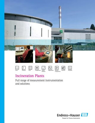
- 1. Incineration Plants Full range of measurement instrumentation and solutions
- 2. Waste storage pit Overhead crane Feed hopper Ram feeder Reciprocating grate Slag discharge Wet deslager Primary air distribution Primary air Secondary air Flue gas recirculation Four-pass steam generator Steam drum Flue gas conveyance Primary air fan Secondary air injection Wet deslagger Incineration plants A waste-to-energy plant is a modern term for contemporary incinerators that burn waste in highly efficient furnaces/boilers to produce steam and/or electricity. Incineration is a waste treatment technology that involves the combustion of organic materials and/or substances. Incineration and other high temperature waste treatment systems are described as thermal treatment“. The incineration of waste materials converts the waste into ashes, flue gases, particulates and heat which can, in turn, be used to generate electricity. Cross section of a waste incineration plant
- 3. Electrostatic precipitator External economizer Gas-to-gasheatexchanger1 Scrubber Gas-to-gasheat exchanger2 Induced draft fan SCRcatalyst Stack Acid flue ash washing Waste scrubber water tank Lime milk station Zinc filter- storage Secondary air fan Muffler Content Level measurement in the steam drum: 4 Traditional dp level measurement: 4 Innovation: Higher plant availability with guided radar measurement: 5 Level measurement using guided radar: 6 Pressure and temperature measurement in water/steam systems 7 Temperature measurement in the boiler: 8 Temperature measurement engineering: 9 Graphic configurator for temperature: 9 Optimizing the water/steam systems Page 1 2 3 Deltatop dp flow measurement in steam/water/air: 10 Differential pressure flow devices: 10 Liquid analyzer in feedwater: 12 4 Page 5 Optimizing further applications Page Level and flow measurement at the scrubber : 14 Limit and continuous level measurement in silos: 16 6 7 Complete supplier Page Comprehensive solutions for power plants: 17 State-of-the-art calibration services 18 Strategic Alliances/Life cycle management 19
- 4. 4 M V L 37.4 % 887 psi 752 °F -.098” LZAHH LZALL 430 °F 1.1 1.1 1.2 1.2 Superheater 2 Superheater 1 Primary air preheater Steam gas drum Steam drum Optimizing the water/steam systems Traditional dp level measurement The key element of the plant is the boiler drum. Its main task is the provision of feedwater, after it has been preheated, to the external economizer, the superheaters and tube nests. Furthermore, saturated steam is withdrawn at this point for primary air and feedwater preheating. Level measurement, the actual key to steam quantity and turbine control, must be highly reliable and consistently available. This main parameter is usually kept constant by a combustion control (multi- component control). However, different parameters of the partly vaporous partly liquid medium to be measured, i.e. water, a boiler pressure of up to 725 psi and temperatures of up to 509 °F place particularly high demands on the instrumentation and its corrective calculations. To achieve a correct measuring signal, the consistencies of the medium in the drum, the condensate reference column, the communicating water column (if externally arranged) and of the superimposed steam in the drum must be taken into consideration. Traditionally, a ∆P measuring point, e.g. Deltabar S PMD75, has been used for this task. The corrective calculation of the medium data can be statically realized for the main operating point of the boiler drum and set as a corrected measuring range in ∆P. Special know-how is indispensable as well as a correct commissioning and calibration procedure, e.g. when filling reference columns or impulse lines. If a sliding corrective calculation is required, correcting components of the DCS/PCS manufacturer can be easily engineered and configured. Level measurement in the steam drum1 dp level measurement of the steam drum with Deltabar S PMD75 1.1 Deltabar S - differential pressure for level measurement Deltabar S differential pressure transmitter is used as a standard for level measurement in the water/steam system. • Very good reproducibility and long-term stability • High reference accuracy • Quick commissioning Deltabar S PMD75
- 5. 1.2 Levelflex M – guided microwave level measurement Levelflex provides level measurement of condensed steam in front of the turbine in the main condenser (hotwell), as well as level measurement at the low pressure preheater, feedwater tank, high pressure preheater and boiler drum. Levelflex provides cyclic automatic gas phase compensation, the ideal solution for precise level measurement in all steam applications. Levelflex is independent of: • Density fluctuations • Changing dielectric numbers • Gas covering of steam • Pressure and temperature changes • Vacuum (e.g. in main condenser hotwell) This results in a better solution than differential pressure for level measurement, providing: • More reliable measurement • Increased safety • Easier installation Innovation: Higher plant availability with guided radar measurement As an alternative to differential pressure, levels can be determined by Levelflex M FMP45 guided wave radar. The instrument may be installed directly from the top using a coaxial tube in the boiler drum or in a bypass chamber next to glass gages. Endress+Hauser can provide the entire bridle/sight glass assembly upon request. Gas phase compensation was developed for these specific applications, in which steam phases occur, to dynamically compensate for the time-of-flight shift which naturally occurs in steam phases. A defined reference section at the probe combined with an electronic software algo-rithm corrects the level value automatically and continually thus offering correct and safe measurement. Furthermore, purging and filling of differential pressure pipes after stoppages is a thing of the past. Level measurement in the steam drum with Levelflex M FMP45 (2 out of 3 installation) Level steam drum Visual steam drum level control through a sight glass Levelflex is ideal as a displacer replacer. It has no mechanical moving parts and, therefore, no wear and tear. Levelflex is suitable for pressures up to 5,800 psig and temperatures up to 752 °F. Levelflex M FMP45 as rod version up to 536 °F Levelflex M FMP45 as coax version up to 752 °F
- 6. 1.2 High pressure preheater Boiler feed pump Feedwater tank Generator Low pressure preheater Condensate pump Additional condensate from full desalination Preheater Intermediate heater Superheater Boiler To flue gas cleaning Vaporizer furnace Steam turbine Condensate Main condenser (hotwell) Steam drum 1.2 1.2 1.2 1.2 Level measurement innovation using guided radar1 Hotwell (main condenser) Low pressure preheater High pressure preheater The boiler feedwater circulates within the water/steam circuit. This is the main component in the power plant. After the steam has condensed in the main condenser, pumps convey the feedwater through subsequent low and high pressure heaters into the boiler. When it arrives at the boiler, the feedwater is vaporized to saturated steam under high pressures (up to 1,595 psig) and high temperatures (up to 605 °F). Passing through several levels of superheater, the steam is then supplied to the turbine to drive the generator. Condensation in the main condenser begins again and the entire procedure is repeated. Monitoring levels in the hotwell, low and high pressure preheater, feedwater tank and boiler drum are of great importance for safe operation of the circuit.
- 7. 0.0 % 0.1 % 12.4 t/h 710 psi 754 °F HP Collector 27 psi 27 psi 25 psi 269.9 °F LP Collector 122 psiA 392 °F 353.4 °F 353.6 °F A 0.0 % 0.1 % 0.2 % 352 °F 352 °F 392 °F A 120 psi 119 psi 352 °F MP Collector R 27 psi 270.5 °F 270.5 °F 285.8 °F 0.0 % A 269.9 °F 268.8 °F 284 °F A A V V V 710 psi A R 2.1 2.2 2.2 Pressure and temperature measurement in water/steam systems 2 2.1 Cerabar S • High pressure impact resistance in the water/ steam circuit • Fast commissioning via quick set-up menu • Unique safety concept for your process application Overheated steam from the superheaters of the boiler enters the steam distributors. This steam is fed to different consumers from the distribution station, turbine, feedwater heater (degasser), process steam for chemical or life sciences plants, warm water heat exchanger for utility-supplied heat, etc. In order to serve all processes, the steam pressure has to be reduced to three levels: • High pressure steam ≈ 710 psi • Medium pressure steam ≈ 120 psi • Low pressure steam ≈ 25 psi A selection of instruments which measure this process with the highest degree of accuracy is: Redundant pressure monitoring at the high and medium pressure distributor and a redundant temperature monitoring in the main pressure pipe by TC15 and the RIT261 display. Cerabar S TC15 2.2 Omnigrad TC15 and TC88 • Predominant use of D4 or D5 solid protecting pipes • Preferred materials: - 16Mo3/1.5415 - 13CrMo4-5/1.7335 • HART®, head or DIN rail transmitter The complete measuring point includes the thermometer and the option of iTemp head, rail or field transmitters.
- 8. Temperature measurement in the boiler3 LAH LAH 1,076 °F 971.7 °F 12392 Nm³/h .08 psi 320.7 °F 406.5 °F PSAL Reciprocating grate Vessel ceiling Superheater Electrostatic precipitator Four-pass steam generator and electrostatic precipitator Temperature measurement at the superheater, horizontal flue Temperature measurement on the boiler ceiling TAF16 3 Omnigrad S TAF16 Thermocouple with a protecting tube of metal • Customized immersion length • Exchangeable measuring insert • Internal ceramic protective sheaths • Thermocouples with different diameters • 2-wire transmitter PC-programmable (4-20 mA), HART® , Profibus® and Foundation Fieldbus™ • Double sensing element • Various materials The waste conveyed to the reciprocating grate is kindled while applying primary and secondary air which also influences and controls the incineration. Temperature measurement in the combustion chamber contributes decisively to the reduction of emissions and pollutants. Temperature measurement arranged directly in the lateral boiler walls at different levels or sensors located in the burn-up zone as well as in the passage of further boiler flues provide information on the combustion temperature.The length and the material of the protecting pipes as well as the mechanical and chemical strain are decisive for the corrosion and useful life of the thermocouples. The aggressiveness of the flue gas must not be dismissed either. The following materials are predominantly used in furnaces: • Burn-up zones: Predominantly 1.4762 / AISI446 or alternatively 1.4841 / AISI310, Type K respectively. The length of the thermocouples is determined by the lining thickness and considerations such as avoidance of mechanical damage by slag or similar materials. • Boiler walls adjacent to the grate: Since the installation is mostly realized with a slight inclination the protecting pipes may bend downwards. The vicinity to auxiliary burners and liquid injections might have a negative influence in this situation. • Boiler combustion chamber ceiling: Since the thermocouples are directly mounted in the flue gas flow we recommend the use of a protective pipe of 1.4876 / Incoloy 800HT with a solidly designed top or alternatively 1.4767 / Kanthal AF® . • Superheater and economizer: The flue gases have now released their high temperatures to the tube nests and other components inside of the steam generator. Thermocouples with protecting pipes of 1.4762 / AISI446 are used at this point.
- 9. Temperature measurement engineering View of the burn-up zone/grate Graphic configurator for temperature Today, the crucial factor of success is cost optimizing across the whole life cycle of a plant. The engineering costs for a temperature measuring point are frequently higher than the purchasing costs of the product itself and engineering, commissioning and maintenance costs together might amount to three times the purchasing costs. For this reason, Endress+Hauser has developed the graphic configurator together with its customers. The same supports engineering in particular with user-friendly navigation. It is thus a useful aid, from sizing, to the operation of a temperature measuring point. Safe sizing of a temperature measuring point with graphic tracing and integrated calculation modules Further information per click: Learn More area, Knowledge data base, Product sheet, Installation instruction, Technical documentation, Certificates, Spare part tracking tool including spare part list The graphic configurator is part of the Endress+Hauser Applicator as described on page 22.
- 10. 10 Deltatop dp flow measurement system in steam, water and air4 Typical dp flow applications Recommended primary elements HP superheated steam into turbine Venturi tube/ venturi nozzle For lowest pressure loss, meets ISO 5167 requirements LP saturated steam/ condensate return Orifice plate Common standard, meets ISO 5167 requirements ISA or venturi nozzle Excellent long term stability, meets ISO 5167 requirements Vortex (Prowirl 73) Calibrated, easiest and cost effective solution up to 6 Primary- and secondary air flow Venturi tube For lowest pressure loss, reduces energy, meets ISO 5167 requirements Differential pressure flow devices - proven in practice. The way to avoid legal disputes on steam measurement. The ISO 5167 standard details the design and volume calculations for orifice plates, venturi tubes and nozzles. This gives significant advantages over other dp types (such as pitot type devices) where no specific standard exists. It is important in contractual or legal agreements to have a common calculation basis to avoid disputes about the volume measured. As an example, it is possible that a new power plant does not produce the thermal efficiency specified in the contract. The boiler supplier and the turbine manufacturer might disagree about the amount of steam actually supplied to the turbine. The use of an agreed standard and a meter of fixed design ensures that third party experts can easily validate the meter, the installation and the design calculations for the steam volume. This will eliminate any potential dispute regarding the energy contained in the steam flow so that thermal efficiency can be accurately quantified. Since the primary element has to be engineered to specific customer or project requirements and sized correctly to provide the required metering accuracy laid down in ISO 5167, the following information must be supplied: • Mass flow or volume flow range • Type of primary element preferred • Range of differential pressures required • Acceptable maximum permanent pressure loss • Nominal pipe diameter • Operating temperature • Operating pressure • Standard base conditions used for reference calculations The choice of the primary element may be important if permanent pressure loss is an issue or is limited by process requirements. Reference texts show the permanent pressure drop as a function of the differential generated as: • Long pattern venturi tube 10-15 % • Short pattern venturi tube 10-20 % • Venturi nozzle 10-20 % • Nozzle 35-60 % • Orifice plates 35-70 % It is not just the primary element selection that is important. The inclusion of condensation chambers, valve manifolds, impulse line length and the location of pressure and temperature sensors is also important in determining the overall system uncertainty as well as assuring a reliable and safe measurement system.
- 11. 11 Typical cost saving case study* What are the savings by using a venturi tube instead of an orifice plate metering the steam into the turbine? Steam parameters: 580 psig, 752 °F, 100 t/h Condensation turbine with exhaust pressure 0.725 psig Power generation: 21.25 MW Annual runtime 8,000 h Savings per MWh produced: $100 Pressure loss of venturi tube = 1.74 psig Pressure loss of orifice plate = 17.4 psig Using a venturi tube instead of an orifice plate increases the power generation output from 21.19 MW to 21.25 MW due to the lower pressure loss at the metering point. This increases the annual energy production by 543 MWh and leads to a savings in excess of $54,000 per year. *Average figures at an incineration power plant Operating instructions for 5-valve manifold Venturi nozzle with condensate pot and shut-off valves Deltabar S Deltatop - steam flow measurement with Deltabar S and annular chamber orifice (710 psi/752 °F) 4 Deltabar S - the heart of any dp flow measuring system • Clear on-site programming with display • Easy and fast commissioning via Quick Setup menu • The HistoROM memory module for fast recommissioning in case the transmitter needs to be replaced • Single-side overload resistance of 6,100 psi (9,140 psi for both sides) provides unsurpassed process safety Our service: www.applicator.com gives you free of charge selection and sizing of your flow measuring system as per ISO 5167 standards. Furthermore, the dp-flow competence team at Endress+Hauser ensures that each custom-made Deltatop dp-flow solution fits correctly. This makes Endress+Hauser the right partner for dp-flow applications.
- 12. 12 High pressure preheater Boiler feed pump Feedwater tank Generator Low pressure preheater Condensate pump Additional condensate from full desalination Preheater Intermediate heater Superheater Boiler To flue gas cleaning Vaporizer furnace Steam turbine Steam drum pH Conductivity Oxygen Condensate pH Conductivity Oxygen pH Conductivity Oxygen Oxygen sensor COS21D Conductivity sensor CLS15D pH sensor CPS41D Liquid analysis in feedwater5 The feedwater of a steam generator must meet certain requirements. It must be free of hardness which would cause the formation of stones and sludge (scale) in the boiler. The formation of scale on the walls of the steam generator increases the sheet metal temperature thus impairing the stability of the boiler sheets. Dissolved gases, e.g. carbonic acid and oxygen, as well as free acids are also not permitted in the water. They would cause corrosion of the boiler sheets and pipes. Finally, the water must be free of mechanic contamination and colloidally dissolved substances like oils and greases to avoid foaming of the boiler content. 5.1 Conductivity sensor CLS15D Why is conductivity measured in the water/ steam circulation system? The conductivity measurement detects the feedwater concentration of ions and measures it in µS/cm. A change in conductivity during operation indicates impurity in feedwater quality. 5.2 pH sensor CPS41D Why is the pH value measured in the water/ steam circulation system? The pH value, (the concentration of hydrogen ions) shows whether a solution is acid, neutral or alkaline. The pH value measurement monitors the feedwater to protect the pipes against corrosion and build-up. 5.3 Oxygen sensor COS21D Why is O2 measured in the water/steam circulation system? The feedwater oxygen concentration is stated in mg/l. High oxygen concentrations promote corrosion of the steel pipes by electrochemical processes and must be continually monitored.
- 13. 13 Liquiline CM42 Memosens technology 5.4 Liquiline M Liquiline is a modular two-wire transmitter for pH, conductivity and oxygen measurement in water- steam circulation systems. Variants are available to connect Liquiline to bus systems like Foundation Fieldbus™, Profibus® and HART® protocol. • Easy commissioning with Quick Setup and Navigator button • Predictive maintenance system recognizes when a sensor has to be cleaned, calibrated or replaced • Combined with Memosens cable breakage is indicated on the display • User-guided commissioning, graphic display and plain text menu • Modular concept: sensor module exchangeable 5.5 Digital sensor for pH value, O2 and conductivity: Memosens Memosens, the first digital sensor worldwide, may be precalibrated at the laboratory. An inductive plug-in connection with bidirectional signal and energy transfer ensures perfect transmission of digital signals between sensor and transmitter. The calibration values are stored in the sensor. The inductive plug-in connection is free of metal and excludes all impairments as they might occur in conventional connections which are not without contact: • Safe, non-contact measurement also in case of humidity • Process data is stored directly in the sensor • Measured data cannot be falsified • Calibration possible at the laboratory • Significantly shorter downtimes of the measuring point • Easier installation without special cable • Predictive diagnostics directly in the sensor system
- 14. 14 A A Flue gas washing level 3 Flue gas washing level 2 Flue gas washing level 1 70.5 % .43 psi .43 psi 7.0 pH 7.1 pH 59.8 % 43.5 psi 29 psi 59.5 % 57.0 % 131 °F 6.1 6.2 6.2 6.2 6 Level and flow measurement at the scrubber Level and flow measurement at the scrubber Flue gas is washed in several stages in the scrubber. A non-contact system is recommended to measure the water circulation of the scrubber sump and the ring jet stage since the medium contains acid flue gas components and a dry content of 0.1-2 %. The pH-value of the scrubber sump usually ranges between pH 0.8-1.5. The installation of ultrasonic transit time clamp-on, non-intrusive sensors is recommended with only one traverse because of this dry content. A single traverse configuration also helps in achieving higher acoustic signal strength values on rubber lined pipes which are typically used in these applications. The response time of this measurement directly influences scrubber protection, i.e. after starting the quench pumps a flow of more than 100 cu. yds./h must be achieved within less that 10 sec. - otherwise the scrubber has to be restarted. Ring jet stage Quench water flow measurement on a rubber lined pipe Prosonic 93P 6.1 Prosonic 93P clamp-on ultrasonic flowmeter Prosonic 93W is an ultrasonic measuring instrument installed directly on pipelines via clamp-on sensors. The transmitter, which is mounted separately, completes the measurement system • External installation allowing easy retrofit with no pipe modifications • Maintenance-free with no moving parts • No obstructions in the pipeline and no pressure loss • Economical alternative for large diameters up to 158” • Portable ultrasonic transmitter for verification and spot checking applications
- 15. 15 To prevent the flue gases from flowing un-washed through the scrubber, several stages within the scrubber are filled with water and their levels are controlled. The acid stage or sump is located at the scrubber inlet, then up to two packed bed stages follow, in which the flue gas is offered a large quantity of packing material, wetted by scrubbing water. The solids stay on the packing material, are washed out and moved downwards. To scrub the remaining suspended solids, the flue gas must pass spraying nozzles on the ring jet stage for the last time and is subsequently made neutral with a pH-value of 7.1. To monitor all differential pressures and gas washing levels, remote seal differential pressure transmitters of the FMD78 type with tantalum as wetted parts are used, partly in a redundant fashion. Deltabar S FMD78 remote seal version 6.2 Deltabar S FMD78 • Very good reproducibility and long-term stability • High reference accuracy: up to ±0.075% • 100:1 turn down, higher upon request • Applications for flow and differential pressure monitoring up to SIL3, certified by TUV SÜD according to IEC 61508 • Memory module HistoROM® /M-DAT • Function controlled from the measuring cell through to electronics
- 16. 16 35 % 0 psi +50 +0 +100 75 °F 7 Limit and continuous level measurement in silos Soliphant M FTM51 7.1 Soliphant M - vibration limit switch for bulk materials Soliphant is a rugged, compact level limit switch for silos containing fine-grained or dusty bulk material. It is used as a high or low level indicator in the lime silo. • Easy commissioning • Maintenance-free with no moving parts • Compact design • Simple and cost-effective Accurate and reliable monitoring of point levels in silos contribute substantially to the safe operation of thermal power plants. Storage tanks supply pulverized lignite coke and quicklime for flue gas cleaning. These substances reduce the flue gas emissions in fabric filters and return flow centrifugal separators. Continuous measurement by Levelflex M and level limit detection by Soliphant M ensure consumption-controlled silo management. Levelflex M FMP40 Separate electronics FHX40 for Levelflex M Level measurement of pulverized lignite coke using Levelflex M FMP40 Residue silos, continuous level measurement of both residue silos by Levelflex M and Soliphant M 7.2 Levelflex M - guided wave radar measurement Levelflex is a compact radar instrument for continuous level measurement, especially for fine-grained bulk material. It provides accurate level indication independent of changing product characteristics. • Suitable for narrow silos or containers • Ideal for fine-grained bulk material such as lime, fly ash and pulverized coal • Maintenance-free, no moving parts • Double safety due to automatic EOP (end of probe) measurement
- 17. 17 Pos. Stk. Hersteller Bezeichnung / Spezifikation Bestell Nr. 1 E+H1 CLM153-A3D00A010Mycom S CLM153 A Zulassung: Ex-freier Bereich 3 Sensoreingang: 2x Konduktiver Sensor D Ausgang: 2x 20mA HART, aktiv 0 Zusätzliche Kontakte: nicht gewählt 0 Hilfsenergie: 100-230VAC A Sprache: Englisch + Deutsch 0 Kabeleinführung: Verschr. M20 1 Zubehör: DAT Modul 0 Einstellung: Werkseinstellung 2 E+H2 CLS19-A1A1ACondumax W CLS19 A Messbereich; Zellkonstante: 0.04-20uS/cm; k=0.01 1A Prozessanschluss/Werkstoff PES Gewinde NPT 1/2/ PES-Zellenschaft 1 Kabelanschluss: Stecker DIN 4-polig, Pg9 A Temperatursensor: Pt100 3 E+H1 50088280Messkabel CYK 71 5m 4 E+H2 YHC314-ADurchlussarmatur für Lf-Sonde CLS 19 Material 1.4435 Ref.: R04201 5 Dr. Thiedig1 PE11PE11 Kationenfilterpatrone 6 Dr. Thiedig1 Austauschermasse zu PE11PE11 Austauschermasse zu PE11 7 Schoch2 GE-SV 12 LR 1/2Gerade Einschraubverschraubung DIN 2353 Ausführung nach DIN 2353 Werkstoff: 1.4571 8 Schoch4 AS SV12 LGerade Anschweissverschraubung DIN 2353 Ausführung nach DIN 2353 Werkstoff: 1.4571 9 1 EO Rohr 12x1.5 mm 1.4571 Ersteller: Datum: Seite: Jue 16.1.08 104Datenblatt Typical: QC-LF-L-XXX-1003 1 5 2 4 2 4 6 9 97 7 9 88 3 Pos. Qty. Manufacturerr Desription Order Code 1 E+H1 CLM153-A3D00A010Mycom S CLM153 2 E+H2 CLS19-A1A1ACondumax W CLS19 3 E+H1 50088280Messkabel CYK 71 5m 4 E+H2 YHC314-ADurchlussarmatur 5 Dr. Thiedig1 PE11PE11 6 Dr. Thiedig1 Austauschermasse zu PE11PE11 7 Schoch2 GE-SV 12 LR 1/2Gerade Einschraubverschraubung DIN 2353 8 Schoch4 AS SV12 LGerade Anschweissverschraubung DIN 2353 9 1 EO Rohr 12x1.5 mm 1.4571 Drawn: Date: Page: Jue 16.01.2008 104Hookup Typical: QC-LF-L-XXX-1003 L1 N 43 42 41 49 48 47 59 58 57 53 52 51 56 55 54 Relais 1 Relais 2 Relais 3 Relais 4 L1 / + N / - 31 32 + - Ausgang / output Q 83 16 15 84 S CLS 19 CLM 253 11 12 13 GN WH YE BK 1 3 2 CYK 71 S .rNlletseBgnunhciezeBrelletsreH.ktS.soP 1 E+H1 CLM153-A3D00A010Mycom S CLM153 2 E+H2 CLS19-A1A1ACondumax W CLS19 3 E+H1 50088280Messkabel CYK 71 5m 4 E+H2 YHC314-ADurchlussarmatur 5 Dr. Thiedig1 PE11PE11 6 Dr. Thiedig1 Austauschermasse zu PE11PE11 7 Schoch2 GE-SV 12 LR 1/2Gerade Einschraubverschraubung DIN 2353 8 Schoch4 AS SV12 LGerade Anschweissverschraubung DIN 2353 9 1 EO Rohr 12x1.5 mm 1.4571 Ersteller: Datum: Seite: Jue 16.01.2008 104Elektro Anschluss Typical: QC-LF-L-XXX-1003 Comprehensive solutions for power plants Complete supplier The trend of outsourcing of industrial services is evident. Cost and competition pressure continues to increase and requires maximum flexibility. Outsourcing of certain internal services permits power plant operators to concentrate more intensively on their own core competencies. The know-how of Endress+Hauser makes sure that the productivity and performance of power plant operators increase. The integration of Endress+Hauser offers chances for cost and process optimization well above the average. Project management • Project management and building site coordination for field instrumentation projects • Nationwide coordination of suppliers • Realization of standardized equipment pools Engineering • Specification of the complete measuring cycle • Interpretation of measuring points and corrections to conditions (screen computation). • Production of technical documentation (hook-ups, electrical connection diagrams, etc.) Installation • Assembly of affected pressure pipes, measuring frames and measurement instrumentation • Building site and assembly monitoring • Final inspection Commissioning • Examination of the mechanical structure • Examination of electrical connections • Cold and warm start-up • Creation of start-up documentation
- 18. 18 Calibration and instrumentation maintenance Focus on your core competence - outsource the rest to the experts Located throughout the US, calibration trailers contain the necessary equipment to calibrate flow, pressure and temperature at your facility. On-site calibration of pressure devices Laboratory calibration of level instruments On-site calibration of analysis devices On-site calibration of temperature instruments Discussion around the metrology plan SOPs, calibration certificates, labels and electronic recordings Factory calibration As a manufacturer of high performance flow measurement devices, Endress+Hauser facilities offer unequaled accuracy and full traceability. In the United States, you can ensure traceability to NIST with A2LA audited accreditations to ISO-17025 for all flow meters you purchase. Our worldwide facilities maintain compliance to the national and international standards of relevance wherever you are - ensuring the best possible service. Endress+Hauser has calibration facilities in the United States, Switzerland, France, the United Kingdom, Japan, India, and China are prepared to meet your calibration support challenges today! Our newest location in La Porte, (near Houston) Texas offers customer in the Gulf Coast region unique capabilities and quicker turnaround. On-site calibration We realize how important it is for you to have this option of “on-site” calibration for numerous reasons - adverse weather, confined spaces, and hazardous areas to name a few. We can offer on-site calibration of all pressure, temperature and flow instruments, regardless of manufacturer! Four categories of critical importance Instruments should be classified according to one of the four categories of critical importance below: • Instruments critical for the product: instruments that, if defective, may have a direct impact on the product quality • Instruments critical for the process/system: instruments that, if defective, may have a direct impact on process or system performance, without affecting the quality of the final product, or safety • Instruments critical for safety/environment: instruments that, if defective, may have a direct impact on operator safety, or the environment • Non-critical instruments: instruments that, if defective, are thought not to have any impact on any of the above www.us.endress.com/calibration
- 19. 19 W@M - Life cycle management Engineering • Fast and safe selection and sizing of the correct measuring instrument for your application • Documentation and administration of projects Procurement • Reduction of procurement costs • Optimization of the quality and speed of your procurement processes • Your price and delivery data is always available on-line Installation • Product documentation is available in different languages • Software versions are always up-to- date Commissioning • Simplified remote commissioning • Increased safety of your personnel • Elimination of time consuming testing Knowledge is a critical factor in the productivity and competitiveness drive. Full knowledge of your plant status allows for good maintenance planning. W@M – Life Cycle Management from Endress+Hauser provides up-to-date and complete information on all of your assets, including products from other suppliers. From engineering, procurement and commissioning through to operation, maintenance and the replacement of individual components, W@M is an open and flexible information platform with on-site tools and services supporting you throughout your plant’s life cycle. Use W@M as a stand-alone solution or it can support your existing systems like Enterprise Resource Planning (ERP) systems or Computerized Maintenance Management Systems (CMMS) using open and flexible interfaces. At any time of the life cycle, W@M provides you with updated knowledge and guarantees time and cost savings while contributing to your competitive edge through constant planning reliability. Operations • Up-to-date information: 24/7 • Effective service, maintenance and optimization of your installed base • Constant reliability planning www.us.endress.com/w@m Combined strengths deliver real customer value Providing world class solutions To meet your needs for complete process automation solutions, the Endress+Hauser and Rockwell Automation strategic alliance offers pre-engineered, pre-tested, supported and maintained solutions, combining best-in- class instrumentation, software and control systems. In support of the increasing requirements for plant- wide control, proven interoperability and value-added differentiation, we are focused on providing: • Reduced integration costs throughout engineering, commissioning and start-up • Optimized plant availability and output • Reduced risk associated with intelligent device integration • Ensured product quality and consistency • Optimized traceability to meet regulatory demands • Predictive maintanance through intelligent devices If you are seeking process improvements or looking to reduce operating costs, our alliance delivers: • Value-added integration • Advanced diagnostics with plant-wide support • Collaborative life cycle management In addition to working with end users, we provide process OEMs, system integrators and architecture and engineering firms worldwide a fully functional, flexible, scalable and affordable Process Control System with tested interoperability and value-added differentiation.
- 20. SO 603B/24/en/04.10 US/INDD CS2 04.10/SCUSA Endress+Hauser’s product portfolio USA Endress+Hauser, Inc. 2350 Endress Place Greenwood, IN 46143 Tel: 317-535-7138 Sales: 888-ENDRESS Service: 800-642-8737 Fax: 317-535-8498 inquiry@us.endress.com www.us.endress.com Canada Endress+Hauser Canada 1075 Sutton Drive Burlington, ON L7L 5Z8 Tel: 905-681-9292 800-668-3199 Fax: 905-681-9444 info@ca.endress.com www.ca.endress.com Mexico Endress+Hauser México S.A. de C.V. Fernando Montes de Oca 21 Edificio A Piso 3 Fracc. Industrial San Nicolás 54030. Tlalnepantla de Baz Estado de México Phone: +52 55 5321 2080 Fax: +52 55 5321 2099 eh.mexico@mx.endress.com www.mx.endress.com International For international locations visit: www.endress.com/worldwide www.us.endress.com/e-direct • Shop on-line for low-cost instruments, devices and components • Capacitance (RF) • Conductive • Mechanical • Vibration • Ultrasonic • Radar • Guided radar (TDR) • Hydrostatic • Gamma Level • Gauge/absolute • Differential pressure • Hydrostatic Pressure • Electromagnetic • Vortex shedding • Coriolis mass flow • Ultrasonic • Open channel • D/P flow Flow • Temperature transmitters • RTDs/thermocouples • Sensors Temperature • Conductivity • pH/ORP • Chlorine • Dissolved oxygen • Turbidity • Chemical analyzers • Nitrate/organic sensors • Sludge level Liquid Analysis • Paperless recorders • Visual data managers • Safety data managers Recorders • Displays • Active barriers • Process transmitters • Power supplies Components • Start-up • Training • Calibration • Maintenance Contracts • Instrument Management Solutions Service ISO 9001 Certified