Prospekt lamellenfugen lr_us_en
•
1 like•883 views

Mageba, juntas estructurales, tecnoav

Recommended
More Related Content
Viewers also liked
Similar to Prospekt lamellenfugen lr_us_en
Similar to Prospekt lamellenfugen lr_us_en (20)
More from José Luis Jarpa
More from José Luis Jarpa (20)
Recently uploaded
Recently uploaded (20)
Prospekt lamellenfugen lr_us_en
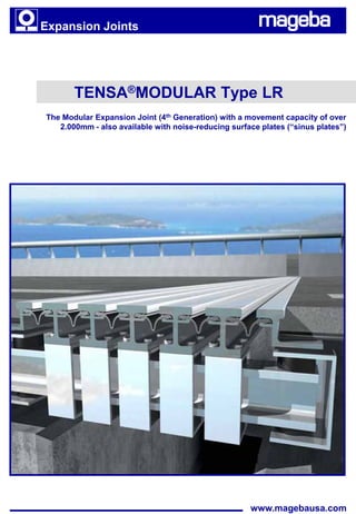
- 1. Expansion Joints TENSA®MODULAR Type LR The Modular Expansion Joint (4th Generation) with a movement capacity of over 2.000mm - also available with noise-reducing surface plates (“sinus plates”) www.magebausa.com
- 2. 2 Introduction Contents Page Introduction 2 Type designation 3 Movement capacities 4 Product characteristics 5 Design details 6 Completed expansion joint Support and control systems 7 Bridge connection 8 Special designs 9 Assembly and installation 10 Quotations and orders 11 Products and references 12 Principle Loading of expansion joint for transport A number of lamella beams divide the movement range at the end of a bridge deck into individual gaps, permitting easy passage of traffic. They are connected with special sealing profiles to form a water-tight unit. mageba has been developing modular expansion joints for decades. This experience results in joints which are well-proven, long-lasting, quiet and low- maintenance. Advantages • Movement in any direction and rotation about any axis possible at any time. • All structural elements of mageba modular expansion joints are made from Assembly of the expansion joint high quality materials. Production is in accordance with the latest ISO 9001:2000 quality assurance requirements. • mageba modular expansion joints have been successfully tested for fatigue and wear at independent institutes. • Weld seams at highly stressed connections are avoided. Therefore, mageba modular expansion joints have high durability. • Clever design facilitates the exchange of individual parts as necessary without difficulty. • mageba modular expansion joints have no loose or moving steel components which would be susceptible to damage from frequent load changes. Movement and torsion are facilitated by lubricated PTFE and high- grade stainless steel, and by elastomeric components and plastics. Expansion joint during installation • The elasticity of the support system absorbs shocks and vibrations and also permits transverse movements. It also allows vertical movements and rotations. • mageba modular expansion joints have an elastic self-regulating gap control system. This system increases the durability of the whole structure, because it helps to absorb the dynamic loads from the traffic passing over it. Any potential damage to the structure caused by the “blocking“ of an individual gap (e.g. by trapped debris) is effectively averted due to the independent elasticity of the steering system. • Only a relatively small recess space is required for the installation of mageba modular expansion joints on bridges and abutments. The asymmetrical arrangement of the joist beam boxes means that they can be adapted to a wide range of situations on site. Expansion joint in service
- 3. Type designation 3 Type designation, movements and dimensions EPDM - seal Lamella beam Edge profile Sliding spring Joist box Joist beam Sliding Sliding Sliding bearing spring bearing Max. Recess space Joint width Type & range of Weight b1 b2 h f0 f5 f65 f80 Size movement mm mm mm mm mm mm mm mm kg/m LR 2 160 400 300 400 140 150 270 300 150 LR 3 240 480 300 400 220 235 415 460 240 LR 4 320 560 300 400 300 320 560 620 330 LR 5 400 640 300 420 380 405 705 780 420 LR 6 480 720 300 420 460 490 850 940 510 LR 7 560 800 300 420 540 575 995 1,100 600 LR 8 640 880 300 440 620 660 1,140 1,260 690 LR 9 720 960 300 460 700 745 1,285 1,420 790 LR 10 800 1,040 300 480 780 830 1,430 1,580 900 LR 11 880 1,120 300 510 860 915 1,575 1,740 1,020 LR 12 960 1,200 300 510 940 1,000 1,720 1,900 1,140 LR 15 1,200 1,490 350 590 1,320 1,395 2,295 2,520 1,400 LR 20 1,600 1,860 350 655 1,770 1,870 3,070 3,370 2,050 LR 25 2,000 2,260 350 675 2,220 2,345 3,845 4,220 2,750 LR 30 2,400 2,660 350 735 2,670 2,820 4,620 5,070 3,500 Main characteristics The type designation is defined by the number of sealing profiles. It follows a modular progression beginning with Type LR2, which has two sealing profiles. In the figure below a Type LR6 modular expansion joint is shown (with six sealing profiles). Example LR6: The range of movements is determined by the operational range of the sealing profile. For instance, if the specified operational range of a sealing profile is 80mm, an LR12 Modular Joint will allow a movement range of 12 x Expansion joint in factory 80 = 960mm. The joint width f changes with movement of the joint. For the minimum joint width fmin the steel profiles are fully closed. For the maximum joint width fmax the gaps between the steel profiles open to 65, 70 or 80 mm, depending on the (national) specification. An example of this can be seen in the above table, where the joint width f is displayed according to the corresponding gap widths (f0, f5, f65, f80 ).
- 4. 4 Movement capacities Movements Modular expansion joints allow movement in all 3 directions (ux, uy, uz) and rotation about all 3 axes (f x, f y, f z). Large movements in the bridge’s transverse direction (uy) and vertical direction (uz) of both the lamella beams and the cross beams are made possible due to the consistent elasticity of the support system. The various rotations Principle of elasticity facilitated by the expansion joint A pre-requisite for ensuring a long lifetime of the modular expansion joint is the avoidance of dynamic stress. Similar to techniques used in the automotive industry, the dynamic stress on mageba modular expansion joints is drastically reduced by the use of a highly developed spring and damping Movement direction (parallel to the bridge axis) Bridge system. The joints and the adjacent structural elements are thus well- protected, and the durability of the joint is significantly increased. β Detailed documents on these spring and damping systems, based on the x principle of elasticity, are available upon request. ux uy Joint axis uz (skewed to the bridge axis) Skewed movements Case 1: Skewed joint axis Generally, modular expansion joints are installed perpendicular to the bridge axis and the direction of their longitudinal movement is parallel to the bridge axis. However, we can easily manufacture expansion joints that are installed at a certain angle to the bridge axis (angle β, Case 1). Movement direction Furthermore, we also manufacture expansion joints for a particular skewed (skewed to the bridge axis) Bridge movement, if the movement direction of the bridge (at the expansion joint) is not perpendicular but at a certain angle α to the joint axis (refer Case 2). 90° x α Movement capacity ux uy Joint axis uz (perpendicular to the bridge axis) The maximum movement capacity in all 3 directions (ux, uy, uz) of TENSA®MODULAR expansion joints, and the angle permitted between the movement direction and its joint axis, are presented in the table below. Case 2: Skewed movement direction Max. angle between Max. longitudinal Max. transverse Max. vertical movement direction and movement movement movement joint axis Type Number of max. uy [mm] a1 £ a/β £ 90° gaps where s = 0 mm where s = 0 mm max. ux [mm] max. uz [mm] where s= 40 mm Standard Special Earthquake where s = 0 mm Standard Special Design Design Design Design Design LR2 2 ± 80 ± 12 ± 50 ± 80 ± 21 a1 = 82° a1 = 58° LR3 3 ± 120 ± 12 ± 66 ± 120 ± 20 85 62 LR4 4 ± 160 ± 12 ± 82 ± 160 ± 20 86 63 LR5 5 ± 200 ± 12 ± 98 ± 200 ± 20 87 64 LR6 6 ± 240 ± 12 ± 114 ± 240 ± 20 88 65 LR7 7 ± 280 ± 12 ± 130 ± 280 ± 19 88 65 LR8 8 ± 320 ± 12 ± 147 ± 320 ± 19 88 66 LR9 9 ± 360 ± 12 ± 222 ± 360 ± 19 89 59 LR10 10 ± 400 ± 12 ± 244 ± 400 ± 19 89 59 LR11 11 ± 440 ± 12 ± 256 ± 440 ± 19 89 60 LR12 12 ± 480 ± 12 ± 277 ± 480 ± 19 89 60 LR13 13 ± 520 ± 12 ± 343 ± 520 ± 32 89 57 LR14 14 ± 560 ± 12 ± 367 ± 560 ± 32 89 57 LR15 15 ± 600 ± 12 ± 391 ± 600 ± 32 89 57 Standard Design: Standard joint with limited transverse movement capacity s: Gap width Special Design: Joint with trumpet-shaped joist box for larger transverse movement requirements ux,y,z: Possible movements in x, y, z direction Earthquake Design: Joint with trumpet-shaped joist box and further adjustments to cope with earthquake movements Attention: Data for TENSA®MODULAR expansion joints in accordance with TL/TP-FÜ are to be taken from the mageba “Regelprüfungsheft LR2-LR15”.
- 5. Product characteristics 5 Proof of quality TENSA®MODULAR expansion joints prove themselves thousands of times every day under heavy traffic conditions. Durability is one of their main characteristics. For more than 40 years they have been successfully used worldwide. Highly-qualified staff, modern manufacturing facilities, and stringent quality control procedures are the fundamental elements which ensure the high quality of mageba products. mageba has been ISO 9001:2000 and EN 729-2 certified since 1991, and holds the European Standard Certificate for Welding according to DIN 18800-7. Materials and corrosion protection Principal components of TENSA®MODULAR expansion joints and their material designation: • S355 steel lamella and cross beams • EPDM or CR sealing profiles • Rubber control and sliding springs from elastomeric material • Sliding bearings from special elastomeric material and PTFE • Special sliding material ROBO®SLIDE used for joints in highly stressed situations The following standard corrosion protection is used for all exposed steel Welding of the joint components: • SA 3 sandblasting • 50µm zinc metal spray galvanizing • two 40µm layers of top coat Components located underneath the expansion joints can be galvanized with a minimum thickness of 80µm. Alternative corrosion protection can be applied upon request. The sliding plates are greased with a special lubricant, and surfaces in contact with concrete are left rough for better bonding. Proven and tested An independent test institute determined the dynamic performance indicators of the system as a whole, such as spring characteristics and damping effects, by conducting roll-over trials. The picture opposite shows a trial structure, in which the joints were tested for movement capability about all three axes. All the components used in mageba modular expansion joints have been thoroughly tested for durability. Testing of the expansion joint Officially approved TENSA®MODULAR expansion joints are approved by numerous national authorities. For example the German government approval TL/TP-FÜ (Stand 03/05), which authorizes modular joints up to type LR15 (with 15 sealing profiles) to be used on motorways, has been obtained. In Austria, mageba modular expansion joints are approved up to type LR12 according to RVS 15.45 standard. Area of application When the movement range of a bridge joint exceeds the operational movement range of a single gap expansion joint (normally 80mm), mageba modular expansion joints can be used. mageba modular expansion joints can be used to facilitate large movement ranges (2000mm and more). The world’s largest expansion joint at present is one produced by mageba for the Run Yang Bridge in China, compromising 27 sealing profiles, with a maximum possible longitudinal movement capacity of 2160mm.
- 6. 6 Design details Recess space The size of the recess space must be determined by the engineer in the early planning stage. The recess space values of the structure must be checked before assembly begins, and corrected as necessary. Cross section Lamella beam Control box Joist box Plan view Anchor (footpath) Anchor (carriageway) Joist box Joist beam Control box Curb units and footpath The outline of the curb, which is formed either by welded-on steel wedges or by cover plates, can be adopted to virtually any bridge edge detail. Standard with Standard cover plates Fascia plates Plan Fascia plates come in a single or double sheet design (see adjacent detail). edge profile A water-tight profile to the lower edge of the fascia is also possible. lamella lamella beam edge profile
- 7. Support and control systems 7 Support system Every lamella beam is supported on each joist beam via a joist frame (see cross-section B-B) which can move on elastically prestressed sliding components along the joist beam. The joist beam is similarly supported at the entrance to the joist box, allowing the joist beam to slide into and out of the joist box. The entire system is thus elastically fixed and free to move. EPDM profile Lamella beam Edge profile Sliding spring Joist box Joist box Joist beam Sliding Sliding bearing Sliding bearing (Cross section A-A) spring Joist frame (Cross section B-B) Control system Elastomeric control springs, in conjunction with the EPDM sealing profiles, coordinate the movement of the individual lamella beams, making them work as a single kinematic system. Thus the overall movement is distributed across the individual gaps, and braking and accelerating forces from vehicles are elastically absorbed. The forces acting on an expansion joint are transferred to the adjacent structures via the control boxes, and can reach the following maximum values: • Horizontally: max. 10KN per control box Control system on the underside • Vertically: max. 18KN per control box In addition, the elasticity of the control system prevents the joint becoming damaged due to blocking of individual gaps by stones etc. lamella axis The exceptional performance and durability of this control system, even under extreme conditions, has been proven in various tests. The result of the tests performed can be summarized as follows: • Faultless even after 9x10⁵ load cycles (movement ±15 mm, 1 Hz, +20°C) • Faultless even at extreme temperatures (between -50°C and +70°C) • Faultless even at high earthquake load (with 100 mm movement per gap) Plan view on Control system
- 8. 8 Bridge connection Connection to reinforcement The reinforcement bars of the adjacent structures should be aligned perpendicular to the joint. They are lapped with the anchor loops of the expansion joint and secured with longitudinal reinforcement. Reinforcement arrangement The connection reinforcement is to be designed according to the rules of Expansion joint during installation reinforced concrete construction. The anchor loops on the edge profile (see drawing on page 7) are normally attached perpendicular to the expansion joint. As a result, the structure’s reinforcement should be placed parallel to the anchor loops. Additional reinforcement should be provided underneath the joist boxes due to the higher loads arising here. In order to guarantee a proper load transfer into the adjacent structural components during the entire life of a joint, mageba recommends the following minimum reinforcement: • Bridge longitudinal reinforcement (Nr. 1 in drawing below): minimum Ø16mm (spacing < 250mm) • Bridge cross reinforcement (Nr. 2): minimum Ø16mm (3 or 5 bars per side, fitted before Fixing of the joint to reinforcement bars installation of the expansion joint) • Additional reinforcement (Nr. 3): minimum Ø12mm (two pieces under each joist box) Edge connections Each bridge requires its own solution for the edge connections. Preferred designs for concrete and steel bridges are shown in the figures below. Concrete bridge Steel bridge with asphalt without asphalt with asphalt without asphalt
- 9. Special designs 9 Noise-reducing surface (optional) Especially in urban areas, expansion joints should be as noise-free as possible. mageba has therefore developed modular expansion joints with an optional noise-reducing surface. The unique patented “sinus plates” with their “teeth” design eliminate straight edges perpendicular to the direction of travel and ensure that vehicles travelling over the joint continuously grip the surface. In this way, noise generated by vehicles travelling over the joint is greatly reduced. In contrast to finger joints, there is no restriction on the type of traffic allowed Lamella joint with sinus plates to travel over modular expansion joints with sinus plates. The special design of these sinus plates also permits cyclists to pass over the joint safely. It is also possible to retrofit existing modular expansion joints with the noise- reducing sinus plates. This requires the surface level of the asphalt adjacent to the joint to be increased by approximately 20mm. Expansion joints with sinus plates are very suitable for use on bridge structures in residential areas and in other areas that are sensitive to noise. Lamella joint after installation Testing and noise measurements Difference in Amplitude (dB) of different joint types At an independent test facility, fatigue testing was carried out on a section of 10.0 lamella beam with bolted-on sinus plates. The durability of the sinus plates 8.0 and the bolted connections was thus proven. level (dB) Noise Noise Level (dB) 6.0 Noise measurements carried out on different structures by an independent facility have shown that modular expansion joints with sinus plates are 4.0 significantly less noisy (up to 70% less noise generated by traffic) than other 2.0 types of expansion joints – see adjacent graph. 0.0 Detailed documents on fatigue testing and noise measurements are available Roller shuter Roller shuter Modular Expansion Joint (450 mm movement range) (450 mm movement range) Modular Expansion Joint (400 mm movement range) range) (400 mm movement upon request. Mat Expansion Joints Mat Expansion Joints (100 mm movement range) range) (100 mm movement Cantilever Finger Expansion Joint Cantilever Finger Expansion Joint (150 mm movement range) range) (150 mm movement Modular Expansion Joint with Sinusplates Modular Expansion Joint with Sinusplates(400 mm movement range) range) (400 mm movement FUSE-BOX: earthquake design Principle of the FUSE-BOX The patented FUSE-BOX protects the joint and adjacent structure from damage during an earthquake. If the expansion gap at the end of a bridge deck closes more than a conventional expansion joint can handle during an earthquake, this can result Normal condition in severe damage to the structure. In order to avoid such damage, it is recommended to equip the expansion joints with the mageba FUSE-BOX. Modular expansion joints equipped with the Fuse-Box are used in areas with high risk of earthquakes. They not only reduce possible damage to the structure, but also ensure that, following an earthquake, emergency vehicles Open beyond maximum (earthquake) are able to cross over as soon as possible. mageba also delivers other earthquake safety systems upon request. Closed beyond maximum (earthquake) Situation after earthquake Installation of the lamella joint by specialists
- 10. 10 Assembly and installation Assembly and transport The TENSA®MODULAR expansion joint is assembled in the factory, ready for installation. It can be transported to site as a single unit for lengths of up to 20 meters, and lifted into position by a crane. Positioning and fixing Lamella joint ready for transport The joint width and pre-settings are checked first. Then the height of the modular expansion joint is precisely fixed in relation to both edge profiles. The joint is secured with installation welding in such a way that it will function even before concreting. Generally, only trained staff authorized by mageba should place the TENSA®MODULAR expansion joints. Detailed assembly and installation instructions can be provided upon request. Retrospective installation possible It is also possible to install the TENSA®MODULAR expansion joints after the road surface has been laid. Procedure: The recess for the joint is initially filled with lean concrete or coarse gravel so that the asphalt can be easily and seamlessly laid. The asphalt and the lean concrete or coarse gravel can then be removed without difficulty at a later point when the modular expansion joint is to be installed. The advantage of the retrospective installation lies above all in the fact that Positioning of a lamella joint the joints can be installed to match exactly the level of the road surface. This optimises driving comfort, reduces impacts, and increases the durability of not only the joint but also the road surface. Formwork and concreting Formwork is fitted on the edge profiles and braced against the joint edges. High-strength concrete (C30/37 (B35) or equivalent) is carefully poured into the recess, which should be kept moist. It is then compacted and levelled, and treated to prevent shrinkage. Important: No concrete must be allowed into the joist boxes Operation and maintenance The TENSA®MODULAR expansion joint’s self-cleaning effect means maintenance is not necessary under normal operating conditions. Checking of condition can be limited to general bridge inspections, when engineers should check watertightness and look for signs of corrosion. In order to identify and repair any damage at an early stage, it is recommended that an annual inspection of the joint is carried out. Detailed instructions for inspections are available upon request. mageba also offers inspection services as required. TENSA®MODULAR joint, Type LR 20 The design of the expansion joint allows any worn parts to be quickly and easily exchanged.
- 11. Quotations and orders 11 Inquiries When making an inquiry, please submit the relevant design criteria for the joint, as this will allow us to give you the ideal choice of joint and the best quotation. Ideally drawings should be provided to indicate the joint geometry. We process quotations immediately and make them available in a short time. Quotations To provide you with a quotation we will need the following documents: • Detailed drawings of the area of the joint (including bridge cross-section) • Range of movement (required movement capacity) • Acceptable individual gap width (e.g. 80mm per gap) • Movement directions (for joints with skewed movements see Page 4) • Asphalt or concrete connection details Special considerations should be outlined in detail in your quote request. Special considerations would include greater movements, edge connections for thicker surfaces or steel superstructures, or modular expansion joints with construction joints, kinks or curvatures. Placing of orders In addition to the above mentioned information, the following documents are also necessary when placing an order: • Layout drawing of the structure • Full details of all possible movements • Pre-setting values Fabrication work begins as soon as the customer has approved and returned the documents with pre-setting values inserted. Delivery time is kept to a minimum thanks to an efficient order processing system and modern manufacturing methods. The main facts about mageba TENSA®MODULAR expansion joints • mageba invented the modular expansion joint, and has been producing them since 1963 • The joints are approved in accordance with numerous standards, e.g. TL/TP-FÜ 92 (Germany) and RVS 15.45 (Austria) • The joints can be fitted with noise reducing surfaces (“sinus plates”) as well as earthquake systems • External quality control conducted by independently approved institute • Quality assurance to ISO 9001:2000 and EN 729-2 certification • European standard welding certificate DIN 18800-7 Stoerebaelt West Bridge, Denmark Fitted with 7 mageba TENSA®MODULAR expansion joints type LR (permitting longitudinal movement of up to 1,200mm)
- 12. 12 Products and references Bridge Bearings - Pot Bearings - Elastomeric Bearings - Earthquake Bearings - Spherical Bearings - Incremental Launch Bearings - Special Bearings - Rocker Bearings Expansion Joints - Single Gap Joints - Modular Expansion Joints - Sliding Finger Joints - Cantilever Finger Joints - Matt Joints - Railway Joints - Architectural Joints Shock Absorbers - Hydraulic Shock Absorbers - Spring Dampers Services - Inspections - Tests - Installations - Refurbishments - Cleaning - Remote monitoring More information on mageba and its products can be found on www.magebausa.com. Worldwide references Version 2008.02 mageba USA LLC mageba gmbh mageba gmbh mageba Bridge Products (Pvt.) Ltd. Bülach, Switzerland Uslar, Germany Kolkata, India New York, NY Tel.: +43-5578-75593 Tel.: +49-5571-9256-0 Tel.: +91-33-22900250 to -253 Tel. 212-653-8813 Fax: +43-5578-73348 Fax: +49-5571-9256-56 Fax: +91-33-22900254 Fax 646-495-3005 oesterreich@mageba.ch uslar@mageba.ch info@mageba.in San Jose, CA mageba (Turkey) mageba (Russia) mageba Bridge Products Pvt. Ltd. Tel.: 408-281-9700 Istanbul, Turkey Moskau - Russia Shanghai, China Fax: 408-281-9701 Tel. +90-262-658 23 80 Tel.: +7-495-967 93 20 Tel.: +86-21-5740 7635 Fax +90-262-658 23 81 Fax: +7-495-967 97 00 Fax: +86-21-5740 7636 engineering connections® info@magebausa.com info@mageba.com.tr info@mageba.ch info@mageba.cn