Cu4201638643
•
0 likes•379 views

International Journal of Engineering Research and Applications (IJERA) is an open access online peer reviewed international journal that publishes research and review articles in the fields of Computer Science, Neural Networks, Electrical Engineering, Software Engineering, Information Technology, Mechanical Engineering, Chemical Engineering, Plastic Engineering, Food Technology, Textile Engineering, Nano Technology & science, Power Electronics, Electronics & Communication Engineering, Computational mathematics, Image processing, Civil Engineering, Structural Engineering, Environmental Engineering, VLSI Testing & Low Power VLSI Design etc.

Recommended
Recommended
More Related Content
What's hot
What's hot (20)
Viewers also liked
Viewers also liked (20)
Similar to Cu4201638643
Similar to Cu4201638643 (20)
Recently uploaded
Recently uploaded (20)
Cu4201638643
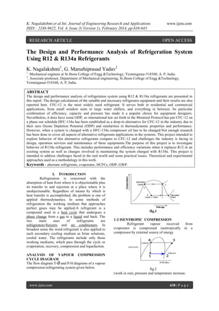
- 1. K. Nagalakshmi et al Int. Journal of Engineering Research and Applications ISSN : 2248-9622, Vol. 4, Issue 2( Version 1), February 2014, pp.638-643 RESEARCH ARTICLE www.ijera.com OPEN ACCESS The Design and Performance Analysis of Refrigeration System Using R12 & R134a Refrigerants K. Nagalakshmi1, G. Marurhiprasad Yadav2 1 . Mechanical engineer at St.Jhons College of Engg &Technology, Yemmiganur-518360, A. P, India. . Associate professor, Department of Mechanical engineering, St.Jhons College of Engg &Technology, Yemmiganur-518360, A. P, India. 2 ABSTRACT The design and performance analysis of refrigeration system using R12 & R134a refrigerants are presented in this report. The design calculations of the suitable and necessary refrigerator equipment and their results are also reported here. CFC-12 is the most widely used refrigerant. It serves both in residential and commercial applications, from small window units to large water chillers, and everything in between. Its particular combination of efficiency, capacity and pressure has made it a popular choice for equipment designers. Nevertheless, it does have some ODP, so international law set forth in the Montreal Protocol has put CFC-12 on a phase out schedule.HFC-134a has been established as a drop-in alternative for CFC-12 in the industry due to their zero Ozone Depletion Potential (ODP) and similarities in thermodynamic properties and performance. However, when a system is charged with a HFC-134a compressor oil has to be changed.Not enough research has been done to cover all aspects of alternative refrigerants applications in the systems. This project intended to explore behavior of this alternative refrigerants compare to CFC-12 and challenges the industry is facing in design, operation services and maintenance of these equipments.The purpose of this project is to investigate behavior of R134a refrigerant. This includes performance and efficiency variations when it replaces R12 in an existing system as well as changes involved in maintaining the system charged with R134a. This project is intended to address challenges faced in the real world and some practical issues. Theoretical and experimental approaches used as a methodology in this work. Keywords - alternate refrigirents, evaporator, HCFCs, ODP, GWP. I. INTRODUCTION Refrigeration is concerned with the absorption of heat from where it is objectionable plus its transfer to and rejection at a place where it is unobjectionable. Regardless of means by which is heat transfer is accomplished; the problem is one of applied thermodynamics. In some methods of refrigeration the working medium that approaches perfect gases may be applied.A refrigerant is a compound used in a heat cycle that undergoes a phase change from a gas to a liquid and back. The two main uses of refrigerants are refrigerators/freezers and air conditioners. In broadest sense the word refrigerant is also applied to such secondary cooling medium as brine solutions, cooled water. The refrigerants include only those working mediums, which pass through the cycle or evaporation, recovery, compression and liquefaction. ANALYSIS OF VAPOUR COMPRESSION CYCLE DIAGRAM The flow diagram T-Ǿ and P-H diagrams of a vapour compression refrigerating system given below. www.ijera.com fIg.1 1-2 ISENTROPIC COMPRESSION Refrigerant vapour received evaporator is compressed isentropically compressor by external source of energy from in a fig.2 (work in out), pressure and temperature increase. 638 | P a g e
- 2. K. Nagalakshmi et al Int. Journal of Engineering Research and Applications ISSN : 2248-9622, Vol. 4, Issue 2( Version 1), February 2014, pp.638-643 2-3 CONDENSATION Compressor discharges vapour into the condenser where it condensed completely i.e. turns in to liquid. Heat is rejected from the refrigerant to cooling medium, usually air or water. 3-4 EXPANSION From condenser liquid refrigerant passes through the expansion valve where it is throttled resulting in a drop of temperature and pressure. However, enthalpy remains constant (throttling expansion) 4-1 EVAPORATION Liquid refrigerant at a low temperature passes into evaporator where it extract heat from the product to be cooled. Due to absorption of extract heat liquid refrigerant turns into vapour, and enters in to the compressor. COEFFICIENT OF PERFORMANCE Work input W=H2-H1 Refrigerating effect N=H1-H4 Since, during the process 3-4, enthalpy is constant. Therefore enthalpy at 4(H4) is equal to enthalpy at 3(H3) Refrigerating effect N=H1-H3 C.O.P=REF EFFECT /WORK INPUT=H1-H3/H2H1 II. DETAILS OF DESIGN AND CONSTRUCTION SELECTION OF COMPRESSOR Compressor specifications Motor H.P=1 H.P. Speed= 640 r.p.m Cylinder specifications No of cylinders = 1 Bore diameter = 63.5 mm Stroke length = 762 mm, Displacement = 4825 cm³ DETAILS OF DESIGN EVAPORATOR The selected evaporator for the design is natural convection bare tube, Dry Expansion, Shell and tube Evaporators. Heat reaches the Evaporator by all three methods of heat transfer and conduction and radiation. www.ijera.com Inlet temperature of the evaporator coil (T 1) = -1.6°C Outlet temperature of evaporator coil (T 2) = 3.4°C Temperature difference between inside and outside of the evaporator = (3.4)+(1.6) = 5 The overall heat transfer, co-efficient “U” factor from data tables for copper = 400kcal/m2-hr-°C Load taken by the evaporator = AU ∆T i.e. Refrigerating capacity = AU ∆T Refrigerating capacity = load taken by Evaporator = 1555 = AU ∆T A = 1555/ U ∆T = 1555/ (400 x 5) = 0.77 m2 Diameter of the coil (D) = 5mm Then A = пDL Length of the coil (L) = A/пD = 0.77/(п x 0.005) = 49.5m2 Length of coil in one turn = 2(40+20) = 180 cm Number of turns in the tank = 4950/180 = 27.4 turns, say 28 turns Provide 10 cm gap between each turn of the coil. The evaporator coil should be arranged the side of the tank that will be easy for periodic cleaning. SELECTION OF CONDENSER The condenser load can be calculated by the following equation: Heat transfer Q=m Cpl (T3-T2) Load on the condenser = m Cpl (T 3-T4) Q = heat absorbed in evaporator + heat of compressor. Heat absorbed in evaporator = 1555 k cal/h Heat of compressor = v x 1 = 220 x 3 =640w = 640 x 0.86 = 550.4 kcal. Q = 1555 + 550.4 = 2105.4 k cal Q = UA ∆T A = 2105.4/ 400 x 22 = 0.239 A = Пdl d = 5mm Length of coil (L) = 0.239 / 0.005 = 15.23m LENGTH IN ONE TURN = (40 + 40) = 80cm Number of turns required = 15.23 / 0.80 = 19.0389 = 20 DESIGN OF EVAPOURATOR fig.4 www.ijera.com 639 | P a g e
- 3. K. Nagalakshmi et al Int. Journal of Engineering Research and Applications ISSN : 2248-9622, Vol. 4, Issue 2( Version 1), February 2014, pp.638-643 www.ijera.com IV. RESULTS & DISCUSSIONS: Graphs are drawn from the above tabulated results. Coefficient of Performance with Evaporator Temperature at a constant Condenser Temperature. Compressor exit Temperature with Evaporator Temperature at a constant Condenser Temperature. Specific Volume at inlet to Compressor with Evaporator Temperature. Variation of Coefficient of performance with evoparator temperature at condensor temperature of 30 oc Replace the compressor. Flush the entire system clean with alcohol and let it be free for few hours. Then rinse it with alcohol again and then blew it clean with DRY AIR (if you don't have a good air dryer for your compressor (or have no compressor), get a good compressed air). Replace all seals on the spring clamp and screwtogether. Put the required amount of lubricating oil in the compressor. Charge with the new R134A refrigerant CALCULATIONS Evaporator Temperature (T 1) = -30ºC Condenser Temperature (T2¹) = 30ºC From charts, At -30ºC, Enthalpy (h1) = 338.143 kJ/kg Entropy (s1) = 1.57507 kJ/ (kg.K) At 30ºC, Enthalpy (h2¹) = 363.566 kJ/kg Entropy (s2¹) = 1.54334 kJ/ (kg.K) Enthalpy (h3) = 228.540 kJ/kg From the graph, s1 = s2 and h3 = h4 We know that, h2 = h2¹ + Cр (T2 – T2¹) Equation – A s2 = s2¹ + Cр ln (T2/T2¹) 1.57507 = 1.54334 + 0.7253 * ln (T2/303) On simplification we get, T2 = 316.5 K Substituting in Equation – A we have, h2 = 363.566 + 0.7253 * (316.5 – 303) = 373.35 kJ/kg (1)Refrigerating Effect = h1 – h4 = 109.603 kJ/kg (2)Coefficient of Performance (C.O.P) = Refrigerating Effect / Work done by the Compressor = (h1 – h4)/ (h2 – h1) = 3.11 www.ijera.com 6 5 4 3 2 1 0 R-12 R-134a -35 -30 -25 -20 -15 -10 -5 0 Temperature in oC fig.6 Variation of C.O.P with evaporator temp.at condenser temperature of 30oc From the Fig.6 It is observed that the coefficient of performance of the refrigeration system is increasing almost linearly as the Evaporator Temperature is increased when the refrigerant used was R-12. the shape of the graph is almost similar when the results were plotted using R134a as the refrigerant however it is observed that the values of coefficient of performance are slightly higher in case of refrigerants R-12 . But refrigerant are R-134a may be preferred because of the zero value of the ozone depletion potential. Variation of Coefficient of performance with evoparator temperature at condensor temperature of 40 oc 6 5 4 3 2 1 0 C.O.P III. STEPS FOR CONVERTING R-12 TO R-134A REFRIGERATOR C.O.P fig 5.Experimental Set-up -35 -30 -25 -20 -15 -10 -5 Temperature in oC R-12 R-134a 0 fig.7 Variation of C.O.P with evaporator temp.at condenser temperature of 40oc From the fig.7 It is observed that the coefficient of performance of the refrigeration system is increasing almost linearly as the Evaporator Temperature is increased when the refrigerant used was R-12. The shape of the graph is almost similar when the results were plotted using R134a as the refrigerant however it is observed that 640 | P a g e
- 4. K. Nagalakshmi et al Int. Journal of Engineering Research and Applications ISSN : 2248-9622, Vol. 4, Issue 2( Version 1), February 2014, pp.638-643 www.ijera.com the values of coefficient of performance are slightly higher in case of refrigerants R-12. But refrigerant are R-134a may be preferred because of the zero value of the ozone depletion potential Variation of Coefficient of performance with evoparator temperature at condensor temperature of 50 oc -35 -30 -25 -20 -15 -10 -5 Temperature in R-12 R-134a 0 oC fig.8 Variation of C.O.P with evaporator temp.at condenser temperature of 50oc From fig8 It is observed that the coefficient of performance of the refrigeration system is increasing almost linearly as the Evaporator Temperature is increased when the refrigerant used was R-12. The shape of the graph is almost similar when the results were plotted using R-134a as the refrigerant however it is observed that the values of coefficient of performance are slightly higher in case of refrigerants R-12. But refrigerant are R-134a may be preferred because of the zero value of the ozone depletion potential fig.9 Variation of Compressor Exit Temperature with evaporator temp.at condenser temperature of 30oc From fig.9 it is observed that the compressor exit Temperatures keeping the Condenser Temperature constant at 30ºC the Evaporator Temperature is varied from -30ºC to 10ºC at intervals of 10ºC it is absorbed that from the graph the compressor Temperature as the Evaporator Temperature is increased from -10ºC to -30 ºC . In case of R-134a the shape of the graph is similar in case R-12. fig.10 Variation of Compressor Exit Temperature with evaporator temp.at condenser temperature of 40oc From fig.10 it is observed that the compressor exit Temperatures keeping the Condenser Temperature constant at 40ºC the Evaporator Temperature is varied from -30ºC to 10ºC at intervals of -10ºC it is absorbed that from the graph the difference in the Compressor exit temperature between R-12 & R-134a is more at an Evaporator Temperature of -30 and is relatively less when the Evaporator Temperature is -10ºC . fig.11 Variation of Compressor Exit Temperature with evaporator temp.at condenser temperature of 30oc From fig.11 it is observed that the compressor exit Temperatures keeping the Condenser Temperature constant at 50ºC the Evaporator Temperature is varied from -30ºC to 10ºC at intervals of -10ºC it is absorbed that from the graph the difference in the Compressor exit temperature between R-12 & R-134a is more at an Evaporator Temperature of -30ºC and is relatively less when the Evaporator Temperature is -10ºC Specific volume C.O.P 6 5 4 3 2 1 0 0.25 0.2 0.15 0.1 0.05 0 -40 -30 -20 -10 Evaporator temperature R-12 R-134a 0 fig.12 Variation of specific volume with evaporator temperature www.ijera.com 641 | P a g e
- 5. K. Nagalakshmi et al Int. Journal of Engineering Research and Applications ISSN : 2248-9622, Vol. 4, Issue 2( Version 1), February 2014, pp.638-643 According to the graph fig.12 the specific volume is plotted against Evaporator Temperature it is observed that the difference in specific volume between R-12 & R-134a is less at an evaporator Temperature of -30ºC and is relatively less when the Evaporator Temperature is -10ºC . From the graphs, we know that Coefficient of Performance for R-12 refrigerant is slightly greater than that of R-134a refrigerant. Even though the C.O.P for R-12 refrigerant is slightly greater than that of R-134a refrigerant, we prefer to use R-134a refrigerant because its Ozone Depletion Potential value is zero. Also, the replacement of CFCs with HFCs provides more efficient refrigeration and does not act as greenhouse gas and the less electricity is needed for refrigeration. V. CONCLUSION It has been observed that the refrigerator test rig is very much suitable for educational purposes. In order to know working of VCR system practically and also for knowing the pressure and temperatures at various points of the cycle. These results will help for modifications and for new designs. It has been seen from the results and graphs that COP of R12 is little greater than COP of R134a. Even though COP of R12 is grater than R134a it must be replaced withR134a because of following reasons. R134a refrigerant is non-toxic and does not flare up within the whole range of operational temperatures. Ozone depletion potential ODP=0, global warming potential GWP=0.25 and Estimated Atmospheric life EAL=16. In Middle temperature refrigeration facilities and air conditioning systems, refrigerating factor of R134a is equal to the factor for R12 or higher than that. In high temperature refrigeration facilities, specific cold-productivity when operating on R134a is also a bit higher than that of R12. Increasing of dehumidifying ability of filter dehydrators due to high hygroscopic property of R134a system-synthetic oil. Improvement of widely used all over the world as a main substitute of R12 for refrigeration equipment operating within middle-temperature range. It is used in automobile air-conditioners, domestic refrigerators, commercial refrigeration middle-temperature equipment, industrial facilities, air-conditioning systems in building and industrial areas, as well as on refrigeration transport. As R134a molecule has smaller size than R12 molecule which makes danger of leakage, this can be avoided by using suitable materials, in particular, with pads, made of such materials as www.ijera.com www.ijera.com “Buna-N”, “Khailaon”, “Neopren”, “Nordel which are more compatible with R134a. REFERENCES [1] [2] [3] [4] [5] [6] [7] [8] [9] [10] [11] S.B. Riffat (2007), “ Comparision of R134a and R12 refrigerants in a vapour compression system”, proceedings of the International Journal of Energy Research, University of Nottingham, Nottingham, U.K, vol .17, pages 439-442. N.J.Shanland (1989), “ Thermo physical properties of 1,1,1,2 – tetra fluoro ethane (R134a)”, proceedings of the International Journal of Thermophysics, Netherlands, vol .10, No.3, PP 591-603. C.Aprea (2001), Department of Mechanical Engineering, University of Salerno, Italy. Molina M.J and Rowlands (1974), “ Stratospheric sink for chlorofluoro methanes, chlorine atom catalysed destruction of ozone”, vol.249, PP 808-812. Parmer .A.S (1995), “ Performance fo hydrocarbon refrigerants in motor car airconditioning”, B.E.thesis, School of Mechanical and Manufacturing Engineering, The University of New South Wales, Sydney. K.Mani and V. Selladura (2008),“ Experimental analysis of a new refrigerant mixture as drop-in replacement”. Proceedings of the International Journal of Thermal Sciences, vol.47, pages 1490-1495. M.Mohanraj, S.Jayraj & C.Muraleetharan (2008),“Environmental friendly alternatives to halogenated refrigerants”.The review of the International Journal of Greenhouse Gas Control. A.Anderson and I.Potts (2003), “A comparision of the operating performance of alternative refrigerants”. The review of Applied Thermal Engineering, vol .23, pages 1441-1451. M.Fatouh, M.EI Kafaty (2006),“Assessment of propane/commercial butane mixture as possible alternatives to R134a in domestic refrigerators”. The review of the energy conversion and management, vol .47, pages 2644-2658. Gallagher, J. Huber (1993), “ Thermodynamic properties of refrigerants and refrigerants mixtures Database (ref prop)”, version 4.0 user’s guide, NIST standard reference database 23, NIST, Gaithersburg MD. S.C. Arora and S.Domakundwar, a course in Refrigeration and Air Conditioning, Dhanpat Rai and sons, 1996. 642 | P a g e
- 6. K. Nagalakshmi et al Int. Journal of Engineering Research and Applications ISSN : 2248-9622, Vol. 4, Issue 2( Version 1), February 2014, pp.638-643 [12] [13] [14] [15] [16] [17] www.ijera.com Dossat R.J., Principles of refrigeration, John Wiley, S.I. Version (1989). W.F.Stoecker, Refrigeration and Air Conditioning, McGraw-Hill Book Company, 1989. Jordon and Priester, Refrigeration and Air Conditioning, 1985. V.K.Jain, Refrigetration and Air Conditioning – S.Chand Company, 1996. http://www.brazeway.com/refrigeration http://progdev.sait.ab.ca/pwen220/119.refcom.htm www.ijera.com 643 | P a g e