B31008012
•
0 likes•240 views

This document analyzes the stress on a robot hand using finite element analysis software ANSYS. The robot hand CAD model was imported into ANSYS and meshed. A static structural analysis was performed considering gravitational and inertial forces. The maximum von Mises stress was found to be 0.89649 MPa. The maximum torque of 1.5 N-mm acted on the thumb joint due to its weight and deformation requirements, while other finger joints experienced between 0.45-0.6 N-mm of torque.

Recommended
Recommended
More Related Content
What's hot
What's hot (12)
Viewers also liked
Viewers also liked (20)
Similar to B31008012
Similar to B31008012 (20)
B31008012
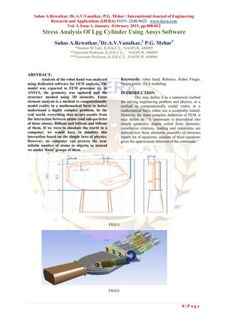
- 1. Suhas A.Rewatkar, Dr.A.V.Vanalkar, P.G. Mehar / International Journal of Engineering Research and Applications (IJERA) ISSN: 2248-9622 www.ijera.com Vol. 3, Issue 1, January -February 2013, pp.008-012 Stress Analysis Of Lpg Cylinder Using Ansys Software Suhas A.Rewatkar,1Dr.A.V.Vanalkar,2 P.G. Mehar3 *Student M Tech. K.D.K.C.E., NAGPUR, 440009 **Assistant Professor, K.D.K.C.E., NAGPUR, 440009 ***Assistant Professor, K.D.K.C.E., NAGPUR, 440009 ABSTRACT: Analysis of the robot hand was analyzed Keywords: robot hand, Robotics, Robot Finger, using dedicated software for FEM analysis. The Finger joints, FEA modeling. model was exported to FEM processor i.e. in ANSYS, the geometry was updated and the INTRODUCTION structure meshed using 3D elements. Finite One may define it as a numerical method element analysis is a method to computationally for solving engineering problem and physics, or a model reality in a mathematical form to better method to computationally model reality in a understand a highly complex problem. In the mathematical form; either one is acceptable indeed. real world, everything that occurs results from However, for more complete definition of FEM, it the interaction between atoms (and sub-particles may define as. “A continuum is discredited into of those atoms). Billions and billions and billions simple geometric shapes called finite elements; of them. If we were to simulate the world in a constitutive relations, loading and constraints are computer, we would have to simulate this defined over these elements; assembly of elements interaction based on the simple laws of physics. results set of equations; solution of these equations However, no computer can process the near gives the approximate behavior of the continuum.” infinite number of atoms in objects, so instead we model 'finite' groups of them. FIG(1) FIG(2) 8|Page
- 2. Suhas A.Rewatkar, Dr.A.V.Vanalkar, P.G. Mehar / International Journal of Engineering Research and Applications (IJERA) ISSN: 2248-9622 www.ijera.com Vol. 3, Issue 1, January -February 2013, pp.008-012 7.3 MATERIAL PROPERTIES OF 1. Solid- generated ansys geometry. STRUCTURAL STEEL Properties of Structural steel are o Mesh- tetrahedral element selection Modulus of elasticity in tension and o Supply model parameters compression, E = 200 X 103 Mpa o Material properties and determine the Modulus of elasticity in shear, G = 80 X 103 constraints. Mpa o Display of results. Ultimate tensile Strength, Sut = 435 Mpa Yield strength in tension & compression, Syt / Syc = 246 Mpa LOADS AND INPUT DATA Yield strength in Shear, Sys = 154 Mpa Analysis of the robot hand has been done Percentage elongation, e = 30 % to check the overall deformation required to robot Specific gravity = 7.8 fingers to grip an object. Possions Ratio, υ= 0.292 Object is kept exactly over the robot palm at the center of hand. Object is spherical shape of Endurance limit in reversed bending, Seb = 183 80mm diameter. (Fig 3).maximum deformation Mpa takes place for thumb joint of 124.25mm while it very for remaining four fingers. Maximum ANSYS PROCEDURE FOR F.E. 700angle required for base joint of the thumb. ANALYSIS Torque required at base joint of all fingers o Model including thumb, is found different. o Geometry- Imported from PROE in “.iges” format FIG (3) Maximum torque is at thumb joint of 1.5 N-mm the current model with the maximum values because of its self weight while torque at remaining required by the application. The palm of robot hand four fingers very form 0.45N-mm to 0.6N-mm as is fixed. A normal temperature distribution of 22° per its respective deformation. (fig 3) C was considered and it was assumed that no other For the input data and loading scheme, the conditions influence the environment gravitational and inertial forces were introduced in . 9|Page
- 3. Suhas A.Rewatkar, Dr.A.V.Vanalkar, P.G. Mehar / International Journal of Engineering Research and Applications (IJERA) ISSN: 2248-9622 www.ijera.com Vol. 3, Issue 1, January -February 2013, pp.008-012 FIG(4) STATIC STRUCTURAL ANALYSIS OF the gravitational forces. The inertial forces were ROBOT HAND introduced as well, to show a complete static The static analysis comprises an analysis of the operational robot. assessment of the total deformation, equivalent (von Misses) stress under the loads mentioned DISTRIBUTION OF STRESSES ALONG above, max shear stress and the fatigue tool i.e. for THE FINGER TIPS ALONG THE THREE life and damage and safety factor. An analysis of AXES non operational robot was done only considering FIG (5) 10 | P a g e
- 4. Suhas A.Rewatkar, Dr.A.V.Vanalkar, P.G. Mehar / International Journal of Engineering Research and Applications (IJERA) ISSN: 2248-9622 www.ijera.com Vol. 3, Issue 1, January -February 2013, pp.008-012 Object Name Joint Probe State Solved Definition Type Joint Probe Boundary Condition Revolute - Solid To Solid Orientation Method Joint Reference System Orientation Reference Coordinate System Options Result Type Force Result Selection All Display All Time Points Maximum Value Over Time X Axis 8.375e-003 N Y Axis 2.6212e-002 N Z Axis 3.4694e-018 N Total 4.7247e-002 N Minimum Value Over Time X Axis -4.376e-002 N Y Axis 0. N Z Axis -1.7347e-018 N Total 0. N VON-MISES STRESS DISTRIBUTION A material is said to start yielding when its von predict yielding of materials under any loading Misses stress reaches a critical value known as the condition from results of simple uniaxial tensile tests. yield strength, . The von Misses stress is used to FIG(6) 11 | P a g e
- 5. Suhas A.Rewatkar, Dr.A.V.Vanalkar, P.G. Mehar / International Journal of Engineering Research and Applications (IJERA) ISSN: 2248-9622 www.ijera.com Vol. 3, Issue 1, January -February 2013, pp.008-012 CONCLUSION modeling & structural analysis of five fingered robot hand is carried out. The modeling is carried by using the Pro – E software. The volume of each link of finger is kept approximately 1214.8 mm³. The CAD model of robot hand in Pro – E is imported in the ansys software for the analysis. The coarse mesh is generated for the whole assembly. TORQUE ACTING thumb -1.5 n mm while torque at remaining four fingers very form 0.45N- mm to 0.6N-mm as per its respective deformation. Overall movement at thumb of 124.25mm VON-MISES STRESS DISTRIBUTION 0.89649 mpa REFERENCES 1. Ikuo Yamano, Takashi Maeno “ Five Fingered Robotic hand Using Ultrasonic Motors and Elastic Elements” Department of Mechanical Engineering, Kieo University Hiyoshi Yokohama 223-8522, Japan. Proceedings of the 2005 IEEE International Conference on Robotics and Automation Barcelona, Spain, April 2005. 2. Dongwoon Choi, Woonghee Shon and Ho-Gil Lee “Design of 5 D.O.F Robot Hand with an artificial skin For An Android Robot” Department of Applied Robot Technology, Korea Institute of Industrial Technology Republic of Korea. Pg.No.85 3. Zhe Xu, Emanual Todorov, Brian Dellon and Yoky Matsuoka “ Design and Analysis of an artificial finger Joint for anthromorphic Robotic hands” Department of computer science & Engineering, University of Washington, WA 98195 USA. 4. Gabriel Gómez , Alejandro Hernandez and Peter Eggenberger Hotz “An adaptive neural controller for a tendon Driven Robotic Hand” Artificial Intelligence Laboratory Department of Informatics, University of Zurich, Switzerland.Pg.No.2-6. 5. Domenico Prattichizzo,, and Antonio Bicchi,“Dynamic “Analysis of Mobility and Graspability of General Manipulation Systems” IEEE transactions on robotics and automation, vol. 14, no. 2, april 1998. 6. Shigematsu, T.; Kurosawa, M.K.; Asai, K. (April 2003), "Nanometer stepping drives of surface acoustic wave motor", IEEE Transactions on Ultrasonics, Ferroelectrics and Frequency Control, 50, IEEE, pp. 376–385 Society of Robot Website, http://www.societyofrobots.com 7. http://en.wikipedia.org/wiki/Robotics“Chp 1 - The Planer Serial Robot hand. 12 | P a g e