Hyundai hl770 7 wheel loader service repair manual
Sm01b
1. HOME
FRONT FORK OIL 1.20
GENERAL x0499x1x
1
PART NO. SPECIALTY TOOL 2
HD-59000-A Pro-level oil gauge
Replace front fork oil:
● At scheduled service intervals as specified in 1.3 MAIN-
TENANCE SCHEDULE. Refer to Table 1-1.
● Prior to storage.
CHANGING FORK OIL 3
1. Have an assistant hold vehicle upright (not resting on jiffy
stand), with front fork pointed straight ahead.
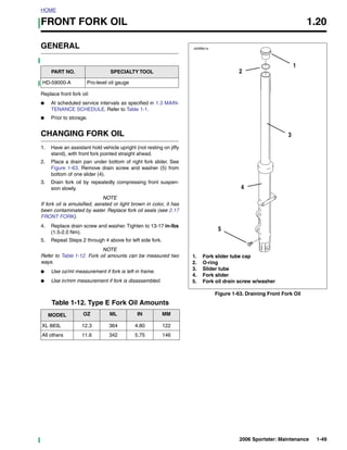
2. Place a drain pan under bottom of right fork slider. See
Figure 1-63. Remove drain screw and washer (5) from
bottom of one slider (4).
3. Drain fork oil by repeatedly compressing front suspen-
sion slowly. 4
NOTE
If fork oil is emulsified, aerated or light brown in color, it has
been contaminated by water. Replace fork oil seals (see 2.17
FRONT FORK).
4. Replace drain screw and washer. Tighten to 13-17 in-lbs
(1.5-2.0 Nm).
5
5. Repeat Steps 2 through 4 above for left side fork.
NOTE
Refer to Table 1-12. Fork oil amounts can be measured two 1. Fork slider tube cap
ways. 2. O-ring
3. Slider tube
● Use oz/ml measurement if fork is left in frame.
4. Fork slider
● Use in/mm measurement if fork is disassembled. 5. Fork oil drain screw w/washer
Figure 1-63. Draining Front Fork Oil
Table 1-12. Type E Fork Oil Amounts
MODEL OZ ML IN MM
XL 883L 12.3 364 4.80 122
All others 11.6 342 5.75 146
2006 Sportster: Maintenance 1-49
2. HOME
Filling Fork Oil: Forks Assembled, in x0631x1x
Frame 2
1. Block motorcycle under frame so that the front wheel is
raised off the ground slightly; this enables front fork to
extend fully and allows most of spring preload (compres-
sion force) to be relieved.
1WARNING
Wear safety glasses or goggles when servicing fork
assembly. Do not remove slider tube caps without reliev-
ing spring preload or caps and springs can fly out, which
could result in death or serious injury. (00297a)
2. Unscrew fork slider tube cap (1) with O-ring (2) from 1
each slider tube (3). Replace the O-ring if damaged or
worn.
x0632x1x
3. Fill each slider tube/slider assembly with 11.6 fl oz. (342
ml) TYPE “E” HYDRAULIC FORK OIL.
4. Install each slider tube cap with O-ring. Tighten to 22-58
ft-lbs (29.9-78.7 Nm).
5. Lower motorcycle to the ground.
Filling Fork Oil: Forks Disassembled, out 1 4
of Frame
1. Position fork tube assembly upright. Remove spring and
compress assembly fully.
2. Pour approximately 12 fl oz. (355 ml) TYPE “E”
HYDRAULIC FORK OIL into fork.
3. See Figure 1-64. Using HARLEY-DAVIDSON PRO-
LEVEL OIL GAUGE, adjust oil level:
a. 4.80 in. (122 mm) for XL 883L.
3
b. 5.75 in. (146 mm) for all models except XL 883L. 1. Fork slider tube
2. Pro Level Oil Gauge (Part No. HD-59000-A)
4. Install spring and slider tube cap with O-ring. Tighten to
3. Fork oil
22-58 ft-lbs (29.9-78.7 Nm).
4. Correct fork oil level is 4.80 in (122 mm) (XL 883L)
5. Assemble fork and install in frame. or 5.75 in (146 mm) (all except XL 883L) below top
6. Repeat this procedure for other fork tube assembly. of fork tube.
Figure 1-64. Refilling Front Fork Oil
1-50 2006 Sportster: Maintenance
3. HOME
SPARK PLUGS 1.21
GENERAL 4636
Harley-Davidson 6R12 spark plugs have a resistor element to
reduce the radio interference which originates in the motorcy-
cle ignition system. Use only the resistor-type spark plugs
specified.
ADJUSTMENT
Spark plug gap is 0.038-0.043 in. (0.96-1.09 mm). Use only
a wire-type feeler gauge. Bend the outside electrode so a
slight drag on the gauge is felt when passing it between elec-
trodes. Never make adjustments by bending the center elec-
trode.
CLEANING AND INSPECTION
Inspection
Examine spark plugs as soon as they have been removed.
The deposits on the spark plug base are an indication of the
spark plug efficiency and are a guide to the general condition
of pistons, piston rings, valves, valve guides, valve seals, car- Figure 1-65. Typical Spark Plug Deposits
buretor and ignition system.
Cleaning
Spark Plug Condition
If spark plugs require cleaning between tune-ups, proceed as
See Figure 1-65. Compare your observations of the spark follows:
plug deposits with the descriptions provided below.
1. Degrease firing end of spark plug using ELECTRICAL
a. A wet, black and shiny deposit on spark plug base, CONTACT CLEANER. Dry spark plug with compressed
electrodes and ceramic insulator tip indicates an oil air.
fouled spark plug. The condition may be caused by
one or more of the following: worn pistons, worn pis- 2. Use a thin file to flatten spark plug electrodes. A spark
ton rings, worn valves, worn valve guides, worn plug with sharp edges on its electrodes requires 25%-
valve seals, a weak battery or a faulty ignition sys- 40% less firing voltage than one with rounded edges.
tem.
3. Adjust spark plug gap. See ADJUSTMENT under 1.21
b. A dry, fluffy or sooty black deposit indicates a carbu- SPARK PLUGS.
retor air-fuel mixture that is too rich, engine idling for
excessive periods of time and/or enrichener usage
for excessive periods of time. INSTALLATION
c. A light brown, glassy deposit indicates an over-
heated spark plug. This condition may be accompa- 1. Before installing spark plugs, check condition of threads
nied by cracks in the insulator or by erosion of the in cylinder head and on spark plug. If necessary, soften
electrodes and is caused by an air-fuel mixture that deposits with penetrating oil and clean out with a thread
is too lean, a hot-running engine, valves not seating chaser.
or improper ignition timing. The glassy deposit on
2. Apply a very light coating of ANTI-SEIZE LUBRICANT to
the spark plug is a conductor when hot and may
spark plug threads. Install spark plug. Tighten spark plug
cause high-speed misfiring. A spark plug with
to 12-18 ft-lbs (16.3-24.4 Nm).
eroded electrodes, heavy deposits or a cracked
insulator must be replaced. If a torque wrench is not available, finger-tighten spark
plug and then using a spark plug wrench, tighten spark
d. A spark plug with a white, yellow, tan or rusty brown
plug an additional 1/4-turn.
powdery deposit indicates balanced combustion.
Clean off spark plug deposits at regular intervals. 3. Check engine idle speed. With engine at operating
See Cleaning. temperature and enrichener OFF (enrichener knob
pushed all the way in), adjust idle speed as necessary.
See 1.25 IDLE SPEED AND IGNITION TIMING.
2006 Sportster: Maintenance 1-51
4. HOME
CABLE AND CHASSIS LUBRICATION 1.22
GENERAL FOOT SHIFT LEVER AND REAR
Inspect and lubricate the front brake hand lever, throttle con-
BRAKE PEDAL
trol cables, clutch hand lever, clutch cable and throttle control
Clean and lubricate the foot shift lever (XL 883C/XL 1200C)
grip sleeve at scheduled service intervals as specified in 1.3
and rear brake pedal pivot with ANTI-SEIZE LUBRICANT at
MAINTENANCE SCHEDULE. Refer to Table 1-1.
scheduled service intervals as specified in 1.3 MAINTE-
If service is on muddy or dusty roads, clean and lubricate NANCE SCHEDULE. Refer to Table 1-1.
components at shorter intervals.
If service is on muddy or dusty roads, clean and lubricate
components at shorter intervals.
CABLES AND HAND LEVERS
JIFFY STAND
CAUTION
Clean and lubricate the jiffy stand at scheduled service inter-
Do not lubricate the enrichener cable or inside of vals as specified in 1.3 MAINTENANCE SCHEDULE. Refer
enrichener cable conduit. The cable must have sliding to Table 1-1. See 2.31 JIFFY STAND for procedure.
resistance to work properly. If service is on muddy or dusty roads, clean and lubricate
See 1.24 THROTTLE CABLES AND ENRICHENER for throt- components at shorter intervals.
tle cable lubricating procedure.
Use SUPER OIL for hand levers. STEERING HEAD BEARINGS
Lubricate the steering head bearings with HARLEY-DAVID-
SON SPECIAL PURPOSE GREASE at scheduled service
intervals as specified in 1.3 MAINTENANCE SCHEDULE.
Refer to Table 1-1.
1-52 2006 Sportster: Maintenance
5. HOME
AIR FILTER ELEMENT 1.23
GENERAL REMOVAL
The air cleaner prevents foreign material from entering the 1. See Figure 1-66. Remove two screws (1) and trim insert
carburetor and engine, trapping airborne dust and dirt in the (2) from air cleaner cover (3).
filter element. 2. Remove air cleaner cover from air cleaner backplate (9).
Service the air cleaner: Remove air cleaner seal (4) from cover.
● At scheduled service intervals as specified in 1.3 MAIN- 3. Remove three screws (5). Remove air filter element (6)
TENANCE SCHEDULE. Refer to Table 1-1. and gasket (7) from air cleaner backplate. Discard gas-
ket.
● More often if the motorcycle is operated in a dusty envi-
ronment.
CAUTION
Install air filter before running engine. Failure to do so
can draw debris into the engine and could result in
engine damage. (00207a)
1. Screw (2) x0502a1x
2. Trim insert
3. Air cleaner cover
9
4. Air cleaner seal
5. Screw (3)
6. Air filter element (includes item 7) 8
7. Gasket
8. O-ring (2)
9. Air cleaner backplate 7
5
6
4
3
1 2
Figure 1-66. Air Cleaner Assembly
2006 Sportster: Maintenance 1-53
6. HOME
CLEANING, INSPECTION AND INSTALLATION
REPAIR 1. See Figure 1-66. Apply a thin coat of engine oil or light
grease to O-rings (8). This will help prevent them from
1. See Figure 1-66. Thoroughly clean air cleaner backplate
being damaged when air filter element is installed.
(9) and inside of air cleaner cover (3).
2. Position new gasket (7) on air cleaner backplate (9).
2. If air filter element (6) is damaged or if filter media cannot
Make sure gasket holes are lined up with backplate
be adequately cleaned, replace element and proceed to
holes.
step 6.
3. Install air filter element (6) onto backplate. The words
1WARNING “This Side Out” should be readable on the upper edge of
the air filter element when installed. Secure with three
Do not use gasoline or solvents to clean filter element. screws (5). Tighten to 40-60 in-lbs (4.5-6.8 Nm).
Flammable cleaning agents can cause an intake system 4. Fit air cleaner seal (4) onto air cleaner cover (3). To
fire, which could result in death or serious injury. ensure proper sealing, make sure air cleaner seal covers
(00101a) entire edge of air cleaner cover.
3. Wash air filter element thoroughly in warm, soapy water. 5. Install air cleaner cover onto backplate. Make sure air
To remove soot and carbon, soak air filter element for 30 cleaner seal fits inside backplate and is not pinched or
minutes in warm water with mild detergent. distorted.
6. Install trim insert (2) and secure cover assembly with two
1WARNING screws (1). Tighten to 36-60 in-lbs (4.1-6.8 Nm).
Compressed air can pierce the skin and flying debris
from compressed air could cause serious eye injury.
Wear safety glasses when working with compressed air.
Never use your hand to check for air leaks or to deter-
mine air flow rates. (00061a)
4. Dry air filter element using low-pressure (32 psi/221 kPa
maximum) compressed air. Rotate air filter element while
moving air nozzle up and down filter element interior. Do
not tap air filter element on hard surface.
5. Hold air filter element up to strong light source. Element
can be considered sufficiently clean if light is uniformly
visible through filter material.
NOTE
Do not use air cleaner filter oil on Harley-Davidson paper air
filter elements.
6. Examine O-rings (8). If damaged, replace with new O-
ring(s).
7. Examine air cleaner seal (4). If cracked, torn or other-
wise damaged, replace with new seal.
1-54 2006 Sportster: Maintenance
7. HOME
THROTTLE CABLES AND ENRICHENER 1.24
CABLE INSPECTION, 10089
LUBRICATION AND ADJUSTMENT
2
Inspect, lubricate and adjust throttle control cables as
described below.
Inspection and Lubrication
1. See Figure 1-67. Remove two screws (1) to separate the
upper handlebar housing from the lower housing.
2. Unhook each ferrule and cable from the throttle grip and
remove the throttle sleeve. 1
3. Inspect each cable. Replace cable assembly if cable is 4
frayed or kinked.
3
4. Inspect entire cable outer sheath from throttle grip to car-
buretor for damage. Replace if necessary. 7
5. Apply a light coat of graphite to the handlebar and
replace throttle grip.
5
6. Pour one or two drops of SUPER OIL into the housing of
6
each cable.
x0505a1x
7. Assemble handlebar housing. Tighten both screws (1) to
35-45 in-lbs (4.0-5.1 Nm).
5
Adjustment 10 4
1WARNING
Check to ensure proper throttle control functions. The
throttle control MUST operate freely without binding.
Irregular or sticking throttle response could result in loss 9
of control of the vehicle and death or serious injury.
See Figure 1-67. With throttle friction screw (3) backed off,
carburetor throttle must return to closed (idle) position. Check 8
control cable adjustment. With engine idling, turn handlebars
through full range of travel. If engine speed changes during 11
this maneuver, adjust control cables according to the follow-
1. Screw (2)
ing procedure.
2. Throttle control grip
1. Loosen throttle friction screw (3). 3. Throttle friction screw
2. Slide rubber boot off each control cable adjuster (6). 4. Throttle control (pull open) cable
5. Idle control (pull close) cable
3. Loosen jam nut (7) on each cable adjuster.
6. Control cable adjuster (2)
4. Turn cable adjusters in direction which will shorten cable 7. Jam nut (2)
housings to minimum length. 8. Throttle cam
5. Point front wheel straight ahead. With engine OFF, turn 9. Spring
throttle control grip (2) to fully open position and hold. 10. Throttle cam stop
6. Gently turn adjuster (6) on throttle control cable (4) until 11. Cable guide
throttle cam (8) touches throttle cam stop (10). Release
throttle control grip and turn adjuster counterclockwise Figure 1-67. Throttle Cable Adjustment
an additional 0-1 turn. Tighten jam nut on throttle control
cable adjuster.
7. Turn handlebars fully to right. Turn adjuster (6) on idle
control cable (5), lengthening sleeve until end of cable
housing just touches spring (9) within cable guide (11).
2006 Sportster: Maintenance 1-55
8. HOME
8. Check adjustment. With throttle friction screw loosened, 1. Loosen hex nut (5) at backside of enrichener bracket (6).
twist and release throttle control grip two or three times. 2. Move cable assembly free of slot in mounting bracket.
Carburetor throttle must return to idle position each time
3. Hold cable assembly at flat (3) with an adjustable
throttle grip is released. If throttle does not return to idle,
wrench. Turn plastic nut by hand counterclockwise
turn idle adjuster, shortening sleeve until correct adjust-
(reducing sliding resistance) until knob slides inward
ment is reached. Tighten jam nut.
unaided.
9. Slide rubber boot over each cable adjuster. Check
4. Turn plastic nut clockwise (increasing sliding resistance)
engine slow idle speed. Adjust if required.
until knob remains fully open without holding, and closes
with relative ease.
ENRICHENER ADJUSTMENT 5. Position cable assembly in slot in bracket with hex nut
and star washer behind bracket. Tighten hex nut (5) to
20-35 in-lbs (2.3-4.0 Nm).
CAUTION
NOTE
Pay close attention to the vehicle's warm-up time. Either Star lock washer (4) is positioned between bracket and hex
excessive or insufficient use of the enrichener may nut.
cause poor performance, erratic idle, poor fuel economy,
spark plug fouling and equipment damage. (00164a)
Inspect enrichener operation at every scheduled service x0605x3x 6
interval.
CAUTION
Do not lubricate the enrichener cable or inside of
enrichener cable conduit. The cable must have sliding
resistance to work properly.
See Figure 1-68. Check fuel enrichener operation. The fuel
enrichener knob (1) should open, remain open and then 1 2 3 5
close without binding. The knurled plastic nut (2) next to the
4
enrichener knob controls the sliding resistance of the 1. Fuel enrichener knob
enrichener control cable within the cable conduit. 2. Knurled plastic nut
3. Flat
4. Star lock washer
5. Hex nut
6. Enrichener bracket
Figure 1-68. Enrichener Control
1-56 2006 Sportster: Maintenance
9. HOME
IDLE SPEED AND IGNITION TIMING 1.25
IDLE SPEED ADJUSTMENT x0506a1x
PART NO. SPECIALTY TOOL
HD-33413-A Carburetor idle adjuster
HD-33413-1A Adjuster tip
Check and adjust engine idle speed as described below.
NOTES
● The CV carburetor enrichener circuit will cause engine to
idle above the normal idle range (950-1050 RPM) with
engine running at normal operating temperature and
enrichener knob pulled out fully. With enrichener knob
pulled out partially, and engine running at normal operat-
ing temperature, engine idle speed will also increase
above normal idle range.
● The increase in idle speed is intended to alert rider that
engine is warmed up to normal operating temperature
and enrichener knob should be pushed in all the way. Figure 1-69. Idle Speed Adjustment Screw
● Continued use of enrichener after engine is at normal
operating temperature WILL cause fouled spark plugs.
1. Start motorcycle and let vehicle reach normal operating Sensor
temperature. Push enrichener knob fully in (enrichener data MAP
closed). sensor
Ignition
2. See Figure 1-69. Adjust idle speed adjusting screw so Control
engine idles at 950-1050 RPM. Module Sensor
a. Turn screw clockwise to increase idle speed. (ICM) data CKP
b. Turn screw counterclockwise to decrease idle sensor
speed.
NOTES
● Use CARBURETOR IDLE ADJUSTER and ADJUSTER
TIP to turn idle adjusting screw if necessary. Ignition coil
control signals
● To adjust the idle speed on models without a tachometer,
use a digital engine tachometer, such as the Snap-On
SE-1100, held near a spark plug cable while the motor-
cycle is idling.
Ignition
Coil
IGNITION TIMING
See Figure 1-70. Ignition timing is controlled by the Ignition
Control Module (ICM) based on input from:
● Manifold Absolute Pressure (MAP) sensor.
● Crank Position (CKP) sensor.
No ignition timing adjustment is required, or possible. Should
a sensor fail, the resulting diagnostic trouble code (DTC) will
identify the problem. See the SPORTSTER MODELS ELEC-
TRICAL DIAGNOSTIC MANUAL for more information. x0552a1x
Figure 1-70. Ignition Control
2006 Sportster: Maintenance 1-57
10. HOME
FUEL SUPPLY VALVE FILTER 1.26
INSPECTION
1WARNING
Stop the engine when refueling or servicing the fuel sys-
PART NO. SPECIALTY TOOL tem. Do not smoke or allow open flame or sparks near
gasoline. Gasoline is extremely flammable and highly
HD-23738-A Plastic Mity-Vac hand pump
explosive, which could result in death or serious injury.
HD-41137 Hose clamp pliers (00002a)
See Figure 1-71. Check fuel valve filter strainer (1) as follows: 2. See Figure 1-71. Remove clamp (8) and fuel hose (9)
from outlet nipple (7). Remove vacuum hose (10) from
1. Turn ignition OFF. See Figure 1-72. Turn fuel supply vacuum nipple (5).
valve handle to OFF (horizontal) position.
CAUTION
x0509a1x Do not allow dirt or fluids to get into the vacuum hose
assembly that connects the fuel valve to the carburetor.
1 Contaminants could block the vacuum signal or inhibit
free motion of moving parts which could cause the fuel
2 valve to remain open.
3. Attach a piece of fuel hose to fuel outlet nipple and route
hose into a proper, clean gasoline container.
3 4. See Figure 1-72. Turn valve handle to RESERVE (handle
6 up).
4
x0510a1x
5
7
10
8
9
1. Fuel strainer
2. Gasket
3. Hex fitting
4. Fuel supply valve assembly 1 2 3
5. Vacuum nipple
6. Fuel supply valve handle 1. OFF
7. Outlet nipple (underneath) 2. ON
8. Clamp 3. Reserve
9. Fuel hose
10. Vacuum hose Figure 1-72. Fuel Valve Operating Positions
Figure 1-71. Fuel Supply Valve
1-58 2006 Sportster: Maintenance
11. HOME
5. See Figure 1-73. Using the appropriate hose adapter, 11. Attach fuel supply valve assembly to tank.
connect the PLASTIC MITY-VAC® HAND PUMP to vac- a. Thread hex fitting (3) on right hand threads of fuel
uum nipple on fuel valve. tank two turns. Collar on hex fitting faces fuel tank.
b. Hold hex fitting and thread body of fuel supply valve
CAUTION assembly into left hand threads of hex fitting two
turns.
Do not apply a vacuum greater than 25 in. of Hg to the
valve at the vacuum nipple to avoid damaging the valve c. Hold fuel supply valve assembly so that handle
diaphragm. points to the left, straight away from motorcycle.
Tighten hex fitting (clockwise) to 15-20 ft-lbs (20.3-
6. Gently apply a vacuum of 1-10 in. of Mercury (Hg) or just 27.1 Nm).
enough vacuum to get a good flow of gasoline through
the valve. 12. See Figure 1-74. Connect the fuel hose to the outlet nip-
ple on the fuel supply valve assembly using new clamp
7. See Figure 1-71. After draining tank, turn the hex fitting and HOSE CLAMP PLIERS.
(3) that attaches the fuel valve assembly (4) to the fuel
tank counterclockwise and remove the valve assembly, 13. See Figure 1-71. Connect vacuum hose (10) to vacuum
gasket (2), and fuel strainer (1). Discard gasket. nipple (5) and fill tank with gasoline. Check for leaks at
fitting.
14. See Figure 1-72. Turn fuel supply valve handle ON and
HD-23738A start engine. No special procedures are required to start
fuel flow. Carefully inspect for leaks. Turn fuel supply
valve OFF and shut off engine after inspection is com-
plete.
FUEL SYSTEM LINES AND
FITTINGS
Inspect the fuel system lines:
● At every scheduled service interval.
● After the fuel tank filter has been serviced.
Check fuel system lines and fittings for leaks.
Figure 1-73. Mity-Vac Hand Pump
(Part No. HD-23738-A)
HD-41137
8. Clean or replace fuel strainer.
9. Coat fuel valve threads with LOCTITE PIPE SEALANT
WITH TEFLON.
10. Install new gasket and fuel strainer on fuel valve assem-
bly.
1WARNING
Do not thread fitting onto valve more than two turns to
avoid “bottoming” fitting on valve. This could cause a
gasoline leak and a fire hazard which could result in
death or serious injury.
Figure 1-74. Hose Clamp Pliers
(Part No. HD-41137)
2006 Sportster: Maintenance 1-59
12. HOME
ENGINE MOUNTS AND STABILIZER LINKS 1.27
INSPECTION 3. Check that all engine mount bolts and stabilizer link
screws are tight. See 2.21 STABILIZER LINKS, 2.22
FRONT ENGINE MOUNT/ISOLATOR, or 2.23 REAR
Check engine mounts and stabilizer links as follows: ENGINE MOUNT/ISOLATOR for torque specifications.
1. See Figure 1-75. Check for cracks or tears in engine 4. Check that the mounts are supporting the weight of the
mount isolator rubber (17, 18). motor.
2. Check stabilizer links (8) for wear.
x0591b1x
10 20
18 4
1
14
8 15
4
16 3
5
4
13
2
7
18
20
9 5
15
8
12
8 4
6
19
4 11 17
3
1. Screw @ 80-120 in-lbs (9.05-13.6 Nm) (3) 11. Nut @ 60-70 ft-lbs (81.4-95.0 Nm)
2. Screw @ 55-65 ft-lbs (74.6-88.2 Nm) (2) 12. Bolt
3. Screw @ 25-35 ft-lbs (33.9-47.5 Nm) (3) 13. Swing arm pivot shaft
4. Screw @ 25-35 ft-lbs (33.9-47.5 Nm) (11) 14. Rear pivot lockplate
5. Washer (4) 15. Stabilizer link bracket (2)
6. Spacer 16. Engine bracket
7. Lock washer (2) 17. Front mount isolator (2)
8. Stabilizer link (3) 18. Rear mount isolator (2)
9. Front isolator mount 19. Grounding strap
10. Rear isolator mount 20. Swing arm pivot bolt @ 60-70 ft-lbs
(81.4-95.0 Nm) (2)
Figure 1-75. Engine Mounting Assemblies
1-60 2006 Sportster: Maintenance
13. HOME
HEADLAMP ALIGNMENT 1.28
INSPECTION 8. Check headlamp beam for proper height alignment:
a. Main beam of light (broad, flat pattern of light)
should be centered equally above and below hori-
1WARNING zontal line on screen or wall.
b. Main beam of light should be directed straight
The automatic-on headlamp feature provides increased
ahead. Properly adjusted headlamps project an
visibility of the rider to other motorists. Be sure head-
equal area of light to right and left of center.
lamp is on at all times. Poor visibility of rider to other
motorists can result in death or serious injury. (00030b) c. Adjust headlamp alignment if necessary. See
ADJUSTMENT which follows.
Check headlamp beam for proper height and lateral align-
ment:
● When the new owner takes delivery of the motorcycle. x0302x7x
● When there is a change in load (adding luggage, etc.).
1. Verify correct front and rear tire inflation pressure. See
1.11 TIRES AND WHEELS.
A
2. Place motorcycle on level floor (or pavement) in an area
with minimum light. 25 ft. (7.62 m)
3. See Figure 1-76. Position motorcycle 25 ft (7.62 m) away A= 35 in. (889 mm)
from a screen or wall. Measure distance from directly
below front axle to base of screen/wall. Figure 1-76. Headlamp Alignment
4. Draw a horizontal line, on screen or wall, 35 in. (889 mm)
above floor.
5. Stand motorcycle upright with both tires resting on floor
and with front wheel held in straight alignment (directly
forward).
6. Load motorcycle with rider, passenger (if normally
present) and any cargo normally carried. Weight will
compress vehicle suspension slightly.
7. Turn ignition/light switch to IGNITION position. Set han-
dlebar headlamp switch to HIGH beam position.
2006 Sportster: Maintenance 1-61
14. HOME
ADJUSTMENT XL 883C, XL 1200C
1. See Figure 1-78. To adjust headlamp horizontally,
XL 883, XL 883L, XL 883R, XL 1200R a. Loosen horizontal adjustment screw (3). Turn head-
lamp right or left as necessary to direct headlamp
1. See Figure 1-77. Remove snap plug (1) from top of beam straight ahead.
headlamp bracket (2). Loosen headlamp clamp nut (3).
b. Tighten horizontal adjustment screw to 30-35 ft-lbs
2. Tilt headlamp up or down to properly aim it in relation to (40.7-47.5 Nm).
the horizontal line and, at the same time, turn it right or
2. To adjust headlamp vertically,
left to direct headlamp beam straight ahead.
a. Loosen vertical adjustment bolt (1) and nut (2). Tilt
3. Tighten headlamp clamp nut to 120-240 in-lbs (13.6-
headlamp up or down to properly aim it in relation to
27.1 Nm) after headlamp is properly positioned. Install
the horizontal line.
snap plug in headlamp bracket.
b. Tighten vertical adjustment bolt and nut to 30-35 ft-
lbs (40.7-47.5 Nm).
4908
10708
2
1
4909 1
2
3
3 1. Vertical adjustment bolt
2. Nut
3. Horizontal adjustment screw
1. Snap plug Figure 1-78. Headlamp Adjustment
2. Headlamp bracket (Custom Models)
3. Headlamp clamp nut
Figure 1-77. Headlamp Adjustment
(Non-Custom Models)
1-62 2006 Sportster: Maintenance
15. HOME
FLUID/LUBRICANT REQUIREMENTS 1.29
BRAKE FLUID ENGINE OIL
1WARNING Engine oil is a major factor in the performance and service life
of the engine. Refer to Table 1-13. Always use the proper
Direct contact of D.O.T. 5 brake fluid with eyes can cause grade of oil for the lowest temperature expected before the
eye irritation, swelling, and redness. Avoid eye contact. next scheduled oil change.
In case of eye contact flush with large amounts of water
If it is necessary to add oil and Harley-Davidson oil is not
and get medical attention. Swallowing large amounts of
available, use an oil certified for diesel engines. Acceptable
D.O.T. 5 brake fluid can cause digestive discomfort. If
diesel engine oil designations include CF, CF-4, CG-4 and
swallowed, obtain medical attention. Use in well venti-
CH-4. The preferred viscosities for the diesel engine oils, in
lated area. KEEP OUT OF REACH OF CHILDREN.
descending order, are 20W-50, 15W-40 and 10W-40. At the
(00144a)
first opportunity, see a Harley-Davidson dealer to change
Use only Harley-Davidson brand D.O.T. 5 BRAKE FLUID. back to 100 percent Harley-Davidson oil.
BRAKE COMPONENT GREASE PRIMARY DRIVE/TRANSMISSION
Use only G40M BRAKE GREASE to lubricate brake system LUBRICANT
components.
Use only GENUINE HARLEY-DAVIDSON FORMULA+
FRONT FORK OIL TRANSMISSION AND PRIMARY CHAINCASE
LUBRICANT.
Use only HARLEY-DAVIDSON TYPE “E” HYDRAULIC FORK
OIL.
Table 1-13. Recommended Engine Oil Viscosity
COLD WEATHER
HARLEY-DAVIDSON HARLEY-DAVIDSON LOWEST AMBIENT
VISCOSITY STARTS BELOW 50˚F
TYPE RATING TEMPERATURE
(10˚C)
HD Multigrade SAE 10W40 HD 360 Below 40˚ F (4˚ C) Excellent
HD Multigrade SAE 20W50 HD 360 Above 40˚ F (4˚ C) Good
HD Regular Heavy SAE 50 HD 360 Above 60˚ F (16˚ C) Poor
HD Extra Heavy SAE 60 HD 360 Above 80˚ F (27˚ C) Poor
2006 Sportster: Maintenance 1-63
16. HOME
STORAGE 1.30
GENERAL 10551
If the motorcycle will not be operated for several months,
such as during the winter season, there are several things
which should be done to protect parts against corrosion, to
preserve the battery and to prevent the buildup of gum and
varnish in the carburetor.
This work should be performed by your local Harley-Davidson
dealer or other qualified technician following Service Manual
procedures.
1WARNING
Do not store motorcycle with gasoline in tank within the
home or garage where open flames, pilot lights, sparks
or electric motors are present. Gasoline is extremely
flammable and highly explosive, which could result in
death or serious injury. (00003a)
1. Prepare fuel system by one of the two methods outlined
below:
a. Fill fuel tank and add a gasoline stabilizer. Use one 1
of the commercially available gasoline stabilizers fol- 2
lowing the manufacturer’s instructions. Turn fuel sup-
1. Carburetor drain screw
ply valve off. See Figure 1-79. Place end of fuel
2. Fuel overflow/drain hose
overflow/drain hose (2) into an approved fuel con-
tainer. Drain all gasoline from carburetor by loosen- Figure 1-79. Draining Carburetor Float Chamber
ing fuel bowl drain screw (1) one full turn; gasoline
will drain through overflow/drain hose. Retighten
drain screw after all gasoline has been drained from
carburetor.
b. Drain all gasoline from the fuel tank. Spray the
inside of the fuel tank with a commercially available
rust preventative. Follow the manufacturer’s instruc-
tions.
2. Fill the oil tank. Locate the hose leading from the oil tank
bottom to the oil pump feed fitting. Remove and plug the
oil pump end of this hose. This prevents oil from seeping
past the check ball into the oil pump and filling the engine
flywheel compartment.
3. Remove the spark plugs, inject a few squirts of engine oil
into each cylinder and crank the engine 5-6 revolutions.
Reinstall spark plugs.
4. Grease wheel bearings and install new seals.
5. Adjust primary chain.
6. Check tire inflation. If the motorcycle will be stored for an
extended period of time, securely support the motorcycle
under the frame so that all weight is off the tires.
7. Wash painted and chrome-plated surfaces. Apply a light
film of oil to exposed unpainted surfaces.
1-64 2006 Sportster: Maintenance
17. HOME
REMOVAL FROM STORAGE
1WARNING
Do not apply any oil to brake discs or brake pads. Oil on
disc pads degrades braking efficiency and can result in 1WARNING
an accident resulting in death or serious injury. The clutch failing to disengage can cause loss of control,
8. Remove battery from vehicle. Charge battery until the which could result in death or serious injury. Prior to
correct voltage is obtained. Charge the battery every starting after extended periods of storage, place trans-
other month if it is stored at temperatures below 60˚ F mission in gear and push vehicle back and forth several
(16˚ C). Charge battery once a month if it is stored at times to assure proper clutch disengagement. (00075a)
temperatures above 60˚ F (16˚ C). 1. Charge and install battery.
2. Remove and inspect the spark plugs. Replace if neces-
1WARNING sary.
Unplug or turn OFF battery charger before connecting 3. Clean the air cleaner element.
charger cables to battery. Connecting cables with 4. If fuel tank was drained, fill fuel tank with fresh gasoline.
charger ON can cause a spark and battery explosion,
5. If oil feed hose was plugged, unplug it and reconnect.
which could result in death or serious injury. (00066a)
6. Start the engine and run until it reaches normal operat-
ing temperature.
1WARNING 7. Check engine oil level. Check the transmission lubricant
Unplug or turn OFF battery charger before disconnecting level. Fill to proper levels with correct fluids, if required.
charger cables from battery. Disconnecting clamps with 8. Perform all of the checks in the PRE-RIDING CHECK-
charger ON can cause a spark and battery explosion, LIST in the Owner’s Manual.
which could result in death or serious injury. (00067a)
1WARNING
Store battery out of reach of children. Battery contains
sulfuric acid which can cause severe burns to eyes, skin
and clothing.
9. If motorcycle is to be covered, use a material that will
breathe, such as light canvas. Plastic materials that do
not breathe promote the formation of condensation.
2006 Sportster: Maintenance 1-65
18. HOME
TROUBLESHOOTING 1.31
GENERAL 8. Ignition timing incorrect due to faulty coil, ICM or sensors
(MAP, CKP and/or TSM/TSSM).
9. Loose wire connection at coil or battery connection or
1WARNING plug between crank position sensor (CKP) and ignition
control module (ICM).
The troubleshooting section of this manual is intended
10. Ignition coil not functioning.
solely as a guide to diagnosing problems. Carefully read
the appropriate sections of this manual before perform- 11. Ignition control module (ICM) not functioning.
ing any work. Observe all cautions and warnings. Failure 12. Crank position sensor (CKP) not functioning.
to observe cautions and warnings could result in death 13. Sticking or damaged valve or valves.
or serious injury.
14. Engine oil too heavy (winter operation).
The following check list can be helpful in locating most oper-
NOTE
ating troubles. Refer to the appropriate sections in this Ser-
For cold weather starts, always disengage clutch.
vice Manual for detailed procedures.
Starts Hard
ENGINE 1. Spark plugs in poor condition, have improper gap or are
partially fouled.
2. Spark plug cables in poor condition.
Starting Motor Does Not Operate or Does
3. Battery nearly discharged.
Not Turn Engine Over
4. Loose wire connection at one of the battery terminals, at
1. Engine run switch in OFF position. coil, or at plug between crank position sensor (CKP) and
2. Ignition switch not ON. ignition control module (ICM).
3. Discharged battery, loose or corroded connections (sole- 5. Carburetor controls not adjusted correctly.
noid chatters). 6. Ignition coil not functioning.
4. Starter control circuit, relay or solenoid not functioning. 7. Engine oil too heavy (winter operation).
5. Electric starter shaft pinion gear not engaging or over- 8. Fuel tank filler cap vent plugged, or carburetor fuel line
running clutch slipping. closed off restricting fuel flow.
6. TSM/TSSM bank angle sensor tripped and ignition 9. Water or dirt in fuel system and carburetor.
switch not cycled OFF then ON.
10. Enrichener valve inoperative.
Engine Turns Over But Does Not Start 11. Air leak at intake manifold.
1. Fuel tank empty or fuel valve turned off. 12. Valves sticking.
2. Fuel valve or fuel strainer clogged. 13. Air cleaner EVAP flapper (if equipped) stuck closed or
inoperative.
3. Engine flooded with gasoline as a result of overuse of
enrichener.
4. Vacuum hose to fuel supply valve disconnected, leaking
or pinched.
5. Discharged battery, loose or broken battery terminal con-
nections.
6. Fouled spark plugs.
7. Spark plug cables in poor condition and shorting, cable
connections loose or cables connected to incorrect cylin-
ders.
1-66 2006 Sportster: Maintenance
19. HOME
Starts But Runs Irregularly or Misses Overheating
1. Spark plugs in poor condition or partially fouled. 1. Insufficient oil supply, or oil not circulating.
2. Spark plug cables in poor condition and shorting or leak- 2. Insufficient air flow over engine.
ing. 3. Leaking valves.
3. Spark plug gap too close or too wide. 4. Heavy carbon deposit.
4. Ignition coil, ignition control module (ICM) or crank posi- 5. Ignition timing retarded. Ignition control module (ICM) or
tion sensor (CKP) not functioning properly. crank position sensor (CKP) defective.
5. Battery nearly discharged.
6. Damaged wire or loose connection at battery terminals Valve Train Noise
or coil. 1. Low oil pressure caused by oil feed pump not functioning
7. Intermittent short circuit due to damaged wire insulation. properly or oil passages obstructed.
8. Water or dirt in fuel system and carburetor or fuel 2. Hydraulic lifter not functioning properly.
strainer. 3. Bent push rod.
9. Fuel tank filler cap vent plugged or carburetor float bowl 4. Cam, cam gears, or cam bushings worn.
vent closed off.
5. Rocker arm binding on shaft.
10. Carburetor controls improperly adjusted.
6. Valve sticking in guide.
11. Air leak at intake manifold or air cleaner.
12. Damaged intake or exhaust valve. Excessive Vibration
13. Weak or broken valve springs. 1. Stabilizer links worn or loose, or stabilizer link brackets
14. Incorrect valve timing. loose or broken.
15. Air cleaner EVAP flapper (if equipped) stuck closed or 2. Isolators worn or isolator bolts loose or broken.
inoperative. 3. Isolator mounting brackets (left side of vehicle) loose or
broken.
Spark Plug Fouls Repeatedly 4. Broken frame.
1. Incorrect spark plug. 5. Primary chain badly worn or links tight as a result of
2. Piston rings badly worn or broken. insufficient lubrication.
3. Fuel mixture too rich (see 4.3 TROUBLESHOOTING). 6. Wheels not aligned, rim(s) bent and/or tires worn.
4. Valve guides or seals badly worn or damaged. 7. Internal engine problem.
Pre-Ignition or Detonation
(Knocks or Pings)
1. Excessive carbon deposit on piston head or combustion
chamber.
2. Incorrect heat range spark plug.
3. Spark plugs not firing.
4. Ignition timing advanced. Ignition control module (ICM)
or crank position sensor (CKP) defective.
5. Fuel octane rating too low.
6. Intake manifold vacuum leak.
2006 Sportster: Maintenance 1-67
20. HOME
ENGINE LUBRICATION SYSTEM ELECTRICAL SYSTEM
Oil Does Not Return To Oil Tank Alternator Does Not Charge
1. Oil tank empty. 1. Voltage regulator-rectifier module not functioning.
2. Return pump gears damaged. 2. Voltage regulator-rectifier not grounded.
3. Oil feed pump not functioning. 3. Engine ground wire loose or broken.
4. Restricted oil lines or fittings. 4. Loose or broken wires in charging circuit.
5. Restricted oil filter. 5. Stator and/or rotor not functioning.
Engine Uses Too Much Oil or Alternator Charge Rate Is Below Normal
Smokes Excessively 1. Voltage regulator-rectifier module not functioning.
1. Piston rings badly worn or broken. 2. Stator and/or rotor not functioning.
2. Valve guides or seals worn or damaged. 3. Weak or damaged battery.
3. Restricted oil filter. 4. Loose connections.
Engine Leaks Oil From Cases, Push Rods, Speedometer Operates Erratically
Hoses, Etc. 1. Contaminated speedometer sensor (remove sensor and
1. Loose parts. clean off metal particles).
2. Imperfect seal at gaskets, push rod covers, washers, etc. 2. Loose connections.
To aid locating leaks, use BLACK LIGHT LEAK DETEC-
TOR (Part No. HD-35457). TRANSMISSION
3. Restricted oil return line to tank.
4. Restricted breather passage(s) to air cleaner.
5. Restricted oil filter.
Shifts Hard
1. Clutch dragging slightly.
FUEL 2. Shifter forks (inside transmission) damaged.
3. Corners worn off shifter clutch dogs (inside transmis-
sion).
Carburetor Floods
Jumps Out of Gear
1. Excessive “pumping” of hand throttle grip.
2. Inlet valve sticking. 1. Shifter pawl improperly adjusted.
3. Inlet valve and/or valve seat worn or damaged. 2. Shifter engaging parts (inside transmission) badly worn
and rounded.
4. Dirt or other foreign matter between valve and its seat.
3. Shifter forks bent.
5. Float misadjusted.
4. Damaged gears.
6. Leaky or damaged float.
1-68 2006 Sportster: Maintenance
21. HOME
CLUTCH Handling Irregularities
1. Tires improperly inflated. Check TIRE DATA Section. Do
not overinflate.
Slips
2. Loose wheel axle nuts. Tighten front nut to 50-55 ft-lbs
1. Clutch controls improperly adjusted. (68-75 Nm). Tighten rear nut to 72-78 ft-lbs (98-106 Nm).
2. Worn friction plates. 3. Excessive wheel hub bearing play.
3. Insufficient clutch spring tension. 4. Rear wheel out of alignment with frame and front wheel.
5. Rims and tires out-of-true sideways. Tire runout should
Drags or Does Not Release not be more than 5/64 in. (2.0 mm).
1. Clutch controls improperly adjusted. 6. Rims and tires out-of-round or eccentric with hub. Tire
2. Clutch plates excessively warped. runout should not be more than 3/32 in. (2.4 mm).
7. Loose spokes (laced wheel vehicles only).
Chatters
8. Irregular or peaked front tire tread wear.
Friction or steel plates worn, warped, or dragging. 9. Tire and wheel unbalanced.
10. Steering head bearings improperly adjusted. Correct
CHASSIS adjustment, and replace pitted or worn bearings and
races. See 2.18 FORK STEM AND BRACKET ASSEM-
BLY.
Irregular/Inadequate Brake Action 11. Shock absorbers not functioning normally.
1. Master cylinder reservoir low on fluid. 12. Heavy front end loading. Non-standard equipment on the
2. Brake system contains air bubbles. front end (such as heavy radio receivers, extra lighting
equipment, or luggage) tends to cause unstable han-
3. Master cylinder or brake caliper piston(s) worn or parts dling.
damaged.
13. Engine mounts and/or stabilizer links loose, worn or
4. Brake pads contaminated with grease or oil. damaged.
5. Brake pads badly worn. Minimum lining thickness is 0.04
in. (1.02 mm).
6. Brake disc badly worn or warped.
7. Brake pads dragging or excessive braking (brake fades
due to heat buildup).
8. Insufficient brake pedal or hand lever free play (brake
drags).
2006 Sportster: Maintenance 1-69