1. Inter AS for IPv6 VRF
By Fred Bovy ccie #3013
3 basic Scenario exists to cover all the needs. These models
can be adapted to cover all the needs of interconnection of MPLS-VPN
Backbones. In IPv4 this is also supported and it is tested with IPv6 and IPv4 or
IPv6 only.
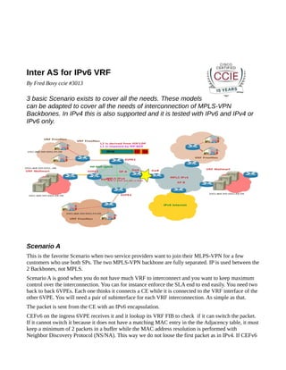
Scenario A
This is the favorite Scenario when two service providers want to join their MLPS-VPN for a few
customers who use both SPs. The two MPLS-VPN backbone are fully separated. IP is used between the
2 Backbones, not MPLS.
Scenario A is good when you do not have much VRF to interconnect and you want to keep maximum
control over the interconnection. You can for instance enforce the SLA end to end easily. You need two
back to back 6VPEs. Each one thinks it connects a CE while it is connected to the VRF interface of the
other 6VPE. You will need a pair of subinterface for each VRF interconnection. As simple as that.
The packet is sent from the CE with an IPv6 encapsulation.
CEFv6 on the ingress 6VPE receives it and it lookup its VRF FIB to check if it can switch the packet.
If it cannot switch it because it does not have a matching MAC entry in the the Adjacency table, it must
keep a minimum of 2 packets in a buffer while the MAC address resolution is performed with
Neighbor Discovery Protocol (NS/NA). This way we do not loose the first packet as in IPv4. If CEFv6
2. find that the route is recursive it applies a stack of label. Then when we have the MAC Address packet
is sent.
The Internal label is the MP-BGP label which has been allocated by the Egress 6VPE MP-BGP
(Gateway A) and sent with the IPv6 Route to the Ingress 6VPE.
The external label is matching the local Gateway A 6VPE /32 loopback address.
Then on Gateway B CEFv6 allocates the external label which are allocated by the neighbor P routers
and is most of the time a POP label to reach the egress 6VPE.
The IPv6 VRF Address is advertised by the MP-BGP packet to all the others 6VPE directly or mostly
via a Route-Reflector.
The Packet goes from the ingress 6VPE to the Internal Gateway A as if it was the destination.
Then it is forwarded to the Ingress 6VPE which will forward it toward the Egress 6VPE.
Illustration 1: InterAS Scenario A
It gives maximum control on the data and isolates the networks so there is no MPLS on the
interconnection. MPLS-VPN parameters can be completely different: RD, RT as long as it leads to the
correct egress 6VPE.
3. Scenario B
The Scenario needs two dedicated gateway with an MP-eBGP + Labels session in between. This way
all the vpnv6 routes are exchanged between the two 6VPEs with all the VRF routing info to reach the
destination.
First we must disable the automatic dropping of all the path which are not imported by any VRF. We
are not going to configure all the VRF on the Gateways.
“no default BGP routetarget filter” command within the BGP address-family vpnv6
configuration
With this method we advertise all the paths. Also, it requires two big dedicated routers.
A Big difference with the previous, we have MPLS running between the two gateways instead of IPv6.
As we use multihop MP-eBGP between the Gateways, the next-hop for the inter VRF communication
will be the advertising Gateway itself. The next-hop self is needed for SP A to be the next hop for any
destination going to SP B.
The packet can cross the link between GwA and GwB thanks to a route and a label advertized by a MPeBGP vpnv6 multihop configuration.
When Gateway B receives the packet it has the two labels needed to encapsulate the packet to the
egress 6VPE.
This solution does not allow the same granularity of control as previous but is much more scalable if
you have 2 big networks to interconnect for the same customer. In this scenario the VRF parameters:
RD and RT must be consistent.
This is a good solution if one of the 2 networks don't use BGP Route Reflector otherwise prefer
solution C.
4. Illustration 2: Scenario B
Scenario C
In this solution we interconnect the Route-Reflectors of the two MSPL-VPN networks so all the vpnv6
routes will be learned with a MP-eBGP session between the RR.
As we connect the two RR of the two MSPL-VPN Networks have different AS so the next hop should
not be changed by the BGP Route Reflectors.
Between the two gateways we need to configure ipv4 routing for SP A to know a route and a label for
each 6VPE loopback and the opposite. eBGPv4 + Label can be used to leak the 6VPE loopback
addresses to the other SP.
5. The Next-hop for the ingress 6VPE will be the Egress 6VPE loopback /32 address, that's why we need
LSP between all 6VPE of both Service Providers. Each SP must know a route and a label for each
remote 6VPE Loopback.
Illustration 3: Scenario C