Streamlining Python Development: A Guide to a Modern Project Setup
6161103 6.3 zero force members
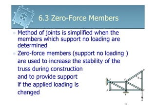
1. 6.3 Zero-Force Members
Method of joints is simplified when the
members which support no loading are
determined
Zero-force members (support no loading )
are used to increase the stability of the
truss during construction
and to provide support
if the applied loading is
changed
2. 6.3 Zero-Force Members
Consider the truss shown
From the FBD of the pin at point A,
members AB and AF become
zero force members
*Note: Consider the FBD of
joints F or B, there are
five unknowns and the
above conclusion
would not be reached
3. 6.3 Zero-Force Members
Consider FBD of joint D
DC and DE are zero-force members
As a general rule, if only two members
form a truss joint and no external load or
support reaction is
applied to the joint, the
members must be
zero-force members
4. 6.3 Zero-Force Members
The load on the truss shown in fig (a)
is therefore supported by only five
members as shown in fig (d)
5. 6.3 Zero-Force Members
Consider the truss shown
From the FBD of the pin of the joint D, DA
is a zero-force member
From the FBD of the pin of the joint C, CA
is a zero-force member
6. 6.3 Zero-Force Members
In general, if three members form a truss
joint for which two of the members are
collinear, the third member is a zero-force
member provided no
external force or support
reaction is applied to the joint
The truss shown is
suitable for
supporting the load P
7. 6.3 Zero-Force Members
Example 6.4
Using the method of joints, determine all the
zero-force members of the Fink roof truss.
Assume all joints are pin connected.
8. 6.3 Zero-Force Members
Solution
Joint G
+ ↑ ∑ Fy = 0; FGC = 0
GC is a zero-force member
meaning the 5kN load at C
must be supported by CB, CH, CF and CD
Joint D
∑ Fx = 0; FDF = 0