SlideShare a Scribd company logo
1 of 80
Download to read offline
MultiMachine, an open-source machine tool
The MultiMachine -- a complete machine shop in
one tool. Entirely built from scrap material.
Pat Delany
MultiMachine
Box 1629, Palestine, Texas 75801 USA
903 723 0980
Support at:
http://groups.yahoo.com/group/multimachine/
1
Introduction
The MultiMachine is a multi purpose machine tool* that a semi-skilled mechanic with just
regular hand tools can build using scrap car and truck parts. Electric power is not needed.
In Developing Countries, the MultiMachine has the potential for saving or improving the lives of
many thousands of people. These machines can be used in many ways:
In the health sector by its use in building water pumps, filters, water well drilling rigs and
hospital furnishings.
In agriculture by its use in building farm machinery and irrigation pumps.
In transportation by its use in building and repairing parts for vehicles.
In communications by its use as as a cell phone charging station.
In village life by being a source of battery power for home lighting.
In education by providing vocational education students with machine tools that they build
themselves and then are able to take back to their villages when they graduate.
It could provide a local self supporting infrastructure that would be available to keep water and
irrigation pumps in repair. Many NGOs go to great effort and expense to drill water wells and
provide pumps in rural areas of underdeveloped countries. These pumps often fail because there
is no person able to repair them. A small MultiMachine based business could provide a pump
repairman with the means to earn a living in an area where these pumps and wells are used. The
pump repairman could support himself by doing machine shop type jobs like making and
sharpening agricultural tools and equipment and resurfacing vehicle flywheels, brake drums and
disks.
Machine tools often draw power intermittently from gas or diesel engines or electric motors. Any
surplus power could run a welding machine built from a vehicle alternator and also recharge
batteries that in turn could be used for home lighting or recharging cell phone batteries.
The combination of a MultiMachine and a welder can be used to build different types of metal
bending and rolling machines that can be used to manufacture fuel efficient cook stoves, pots,
pans and similar products.
The MultiMachine also provides a way to machine simple zinc and aluminum castings made
from the metal found in old car parts. Without this machining, the castings are of limited use but
simple machining can turn them into hundreds of different kinds of products.
Vocational education takes "hands on" learning. Few vocational schools in developing countries
have sufficient numbers of the machine tools that are necessary for training students. This is no
problem with student built MultiMachines.
* A machine tool is a powered mechanical device, typically used to fabricate metal
components
2
Look around you. Almost every manufactured product that is made of metal is a
combination of parts that have been machined (castings, screws and bolts) and sheet, bar
and tubular metal that has been welded, bent, rolled or spun into a needed shape. The
essentialy free MultiMachine and the tools it can produce can do all this.
A group of specialized MultiMachines can do much more. The MultiMachine can be easily
built in dozens of special versions that are specially built to do just a single type of metal
working job. If these special machines were grouped together and driven from a common
power source, they could be used in a form of Developing World mass production. Most of
these machine versions could be built with just one or two broken vehicle engines, a piece
of pipe, a few feet of steel bar, a sack of cement and a few easily made zinc/aluminum
castings.
I am certain that MultiMachine newsgroup members will help adapt our designs to the
types and sizes of material available in any community.
Special thanks to George Ewen of “Engine Mill” fame, Jeff Hansen, Kevin
Olson and to my craftsman friend, Frank Patterson.
And a very special thanks to my wife, Clarissa, who put up with me during the
four years this project took.
3
Table of contents
page
1 Cover
2 Introduction
4 Table of Contents
6 What the MultiMachine can do
10 5 construction techniques ( secrets)
1 Using engine blocks as building blocks
2 Boring the block to fit the bearing outside diameter
3 The spindle can be a piece of pipe the diameter of the bearing inside diameter
4 The use of a three bearing spindle
5 The engine blocks are clamped together with plate and keystock rather than dovetails
12 The machine is made of 5 modules that attach to a vehicle engine block
1 The vertical slide
2 The drive unit
3 Mounting the machine
4 The overarm
5 The spindle
13 About money, accuracy and skills
15 Tools
17 Construction starts
The spindle in detail
22 Step 1, What do you want your machine to do?
Step 2, Really learn the instructions!
Step 3, Getting the stuff together.
24 Step 4, The machine and engine shops
Step 5, When you get the blocks to your shop
25 Step 6, The MultiMachine needs something to sit on
26 Step 7, Modifying the block
29 Step 8, Mounting the block
Step 9, Powering the machine
34 Step 10, The big plate that replaces very hard to make dovetails
38 Step 11, Mounting the big plate
39 Step 12, The vertical slide
43 Step 13, The cross slide
48 Step 14, The overarm
50 Step 15, Building your own “Broken bit” (tangential) cutting tools
52 Step 16, Building your own lathe chuck
4
53 Step 17, How to cut threads (the way it was done 90 years ago, it still works today)
54 How to build a really big MultiMachine
54 The ratchet drill
55 Two easy to build "temporary" lathes
57 The "giant" MultiMachine.
60 Pipe size chart
63 Morse taper chart
64 Metric bearing chart
66 Glossary
5
The MultiMachine is a metal lathe that can be built to
machine something as big as a manhole cover!
It can face and cut tapers by simply rotating
the cross feed on the “turntable.”
It can drill and bore in many different ways
It's an end mill
It's a horizontal mill that can work well with really cheap eBay
cutters! This resharpened cutter cost 75 cents!
My MultiMachine made a 400rpm
single pass-cut of .822” x 1/2” in this
piece of 6061 aluminum.
Other arbors can be easily made
for fly cutters, wood and metal saw
blades, surface grinding wheels and sanding drums and discs.
6
How can the MultiMachine do all these things?
In almost every kind of machining operation, either the work piece or the cutting tool turns. If
enough flexibility is built into the parts of a machine tool involved in these functions, the
resulting machine can do almost every kind of machining operation that will physically fit on it.
You may have heard of 3-in-1 machine tools -- basically a combination of lathe, mill and drill
press. The MultiMachine starts there but adds many other functions. It can be a 10- in-1 (or even
more!) machine tool that is built by using vehicle engine blocks in a LEGO-like fashion.
It can be built as a one-engine block machine with a plate and
angle iron vertical slide.
Or as a two-block version with an engine-
block-based vertical slide.
Or as a two-block-lathe-only version. (See the fixed lathe bed version below.)
This is a three-block version with a fixed,
long lathe bed and a rear-mounted vertical
slide. Great if you have limited space! This
version is similar to a Kitchen and Wade
multipurpose machine (below) that was used
aboard ships for many years -- a far more
useful design for a machine tool than the
common 3-in-1 machine.
“
7
“Double-sided” MultiMachines (lathe on one side, all-function machine on the other) are perfect
candidates for Variable Frequency Drives that make the machine spindles both variable speed
and bi-directional. Pictured below is a four-block version with doubled vertical blocks mounted
back to back so it can support a 4'-long spindle – useful with a heavy chuck. The machine can
also have a rear vertical slide, and a 4- or 5-block version with a Bridgeport-like head could have
an added horizontal block with powered spindle added on top.
The most common size for a MultiMachine has 12-to-15" of table vertical travel and a 32" lathe “swing.” The
horsepower required for regular lathe-type cutting tools makes them hard to use large work pieces. BUT...If you
replace the cutting tool with a simple $30 bench grinder or even a homemade toolpost grinder, you can machine
really big jobs. You can even resurface large clutch and brake parts for a truck.
By using the simplest metal casting technique, a skill that has been around thousands of years,
you can turn out products using machined aluminum alloy. It then becomes possible to build
things like pump parts and to cast alloy bushings that could replace expensive ball bearings. One
common alloy, ZA-12, contains about 12% aluminum, with zinc as most of the remainder. Both
8
aluminum and zinc are materials commonly used in vehicles, making them easily available. ZA-
12 has a tensile strength approaching that of cast iron and is such a good bearing material that it
is used for bushing-type bearings in steel-rolling mills.
See the possibilities?
9
The MultiMachine is extremely simple - basically 6 unusual construction techniques that
we call “secrets” and 5 very simple “modules” that bolt to an engine block.
Using engine blocks as building blocks is the first MultiMachine “secret.” Since cylinder bores
are bored parallel to each other and at exact right angles to the cylinder head surface,
MultiMachine accuracy begins at the factory where the engine block was built.
The second MultiMachine secret! In the most common version of the MultiMachine, one that
has a roller bearing spindle (the kind I built), this precision is maintained during construction
with simple cylinder re-boring of the #3 cylinder to the size of the roller bearing outside diameter
(OD) and re-boring the #1 cylinder to fit the overarm OD.
The best part is that the cylinder-boring operations will probably cost less than $50. An engine
machine shop provides the most inexpensive and accurate (.0005" on a 4" cylinder!) machine
work commonly done anywhere and guarantees you that the spindle and overarm will be both
aligned and at an exact right angle to the face (head surface) of the main engine block that serves
as the base of the machine.
The third MultiMachine “secret!” The spindle can be as simple as a piece of pipe machined to
fit the inner diameter of the bearings.
The fourth “secret” is the addition of a third bearing to the spindle. The three-bearing spindle
is necessary because the “main” spindle bearings just “float” in the cylinder bore so that the third
bearing is needed to “locate” the spindle, act as a thrust bearing, and support the heavy pulley.
The fifth MultiMachine secret! The main engine block and the vertical-slide engine block fit
together with the help of two 1/2" x 12" steel plates, along with my unique way of clamping the
plates together. It's easily built, easily adjusted, and easily clamped into position without the
workpiece moving. Far superior (I think!) to a homemade attempt at a four-foot-long dovetail.
Long, angled cuts similar to this
commercial dovetail assembly on the cross
slide shown below would be far more
difficult to build than the MultiMachine's
simple, square sections that are bolted
together. While the MultiMachine vertical
slide requires only a drill to build, a long
dovetail requires a very large milling
machine. A hugely important difference!
10
The use of smaller steel bar stock or angle iron may be necessary in some areas where the
½” x 12” steel plate may be hard to find. Pieces of truck frame rail could be used.
Alignment of these “foundation” parts is critical, and substitutes for the preferred steel
plate may be harder to adjust. Don't let the difficulty of making a sliding fit deter you from
getting started. Build a fixed-bed lathe version first and later add a MultiMachine-type
vertical slide to the rear of the block.
Here is one kind of substitute
that could work well: “doubled”
frame walls that are common in
big trucks. The rivets can be
ground off and the two pieces
made into a good sliding fit.
The sixth MultiMachine secret is a device similar to this that
can be clamped to a shaft. It can have capscrews that pass
sideways in order to push or pull another device or can be
made large enough to do dozens of jobs by itself. More
about this later!
11
The 5 simple modules that attach to the
engine block:
(1) The vertical slide module is basically a short engine block
with a steel plate bolted to the head surface and a cross slide
attached to to the end bell (upper) end. There are many kinds of
cross slides that can be bought or built. If you have a little
money to spend, think about buying a $69 ENCO one to use at
first (in developing countries, however, a similar one may be the
equivalent of a thousand dollars). Later, you can build something
like a massive concrete and steel “Romig” single or twin lathe
bed and cross slide. (See the “Romig” turret lathe design in the MultiMachine newsgroup “files”
section.) J.V. Romig designed machine tools that were featured in Popular Mechanics magazine
for almost thirty years. The designs still work well. This small cross slide also can be used for
many other projects. Example: you can fit it on top of a turntable and use it for cutting tapers. (A
turntable could also be fitted to the top of a big “Romig” bed to cut tapers.)
(2) The drive unit module. There are literally dozens of ways
to drive the machine. A combination of small and large pulleys
makes a good medium-speed drive. Other setups might include
multiple-groove pulleys or even the transmission from a lawn
mower, garden cultivator, or pickup truck. Power can be
provided by anything from an electrical appliance motor to a car
or truck engine.
(3) The machine mount module
The quality of the finish your machine can make will be
greatly affected by the rigidity and weight of the base.
Since I lack work space, I had to have a machine that I
could move around. Mine is built with an engine stand
and mobile base. (A permanent base made from concrete
or a heavy steel frame would be much more rigid.)
An overhead hoist is a necessity since you'll be using a
machine that may weigh well over a ton. If you decide to
use an engine-stand-type machine mount, try to make it
a one-ton model. In the USA, Harbor Freight has these
for about a hundred dollars.
12
(4) The overarm module may not
even be needed by some people but
others may see it as the heart of an
entire tooling system. Because it is
important that the overarm always stay
in alignment, the #1 cylinder is re-
bored to fit your overarm pipe at the
same time the #3 cylinder is re-bored
for the spindle.
(5) The spindle module is the heart of the machine. No machine tool can do a proper job with
an inaccurate spindle. Because the bearings actually run in the professionally bored cylinder
bore of the engine block and the spindle is finish-machined on the MultiMachine itself,
accuracy is achievable even by a novice machinist. (To be treated in much more detail later)
Accuracy, money, tools and skills
Your machine's accuracy is determined by the care you put into building it. There's no one
checking your mistakes but you. Compounding a few barely-good-enough fits could make you
end up with a machine that chatters too much to use. The chattering may be so severe that you
can't even discover what causes it.
Safety also depends on you. ALWAYS use protective guards on your machine. I can't stress it
enough. Also...the MultiMachine is taller than it is wide, is very heavy, and is prone to fall over!
Mine fell on me once and now I have a new, titanium knee! I liked the old one better.
13
A little extra work lets you save a lot of money! I'm assuming that you would like to spend as
little money as possible on this project. If you can afford to spend a lot, just search eBay and
Craig's List for some of those wonderful machines left behind when US jobs went to China.
When I built my MultiMachine, I tried to find ways to build it that could take almost no money
and little or no electrical power either for building or operating it. I wanted a machine that could
be built and run anywhere in the world – outdoors, in a shed without power, or in the finest
workshop. The result is a machine that could be grouped with others like it to make a small
factory. The machines could be powered by a single gas or diesel engine running an overhead
shaft that is connected to them by simple pulleys and belts.
You may have to learn a few new skills to build the machine, but these skills are also
needed to make best use of the MultiMachine.
Two important skills covered in many old machining books are grinding cutting tools to the
correct shape and clamping work on a lathe faceplate. These kinds of subjects are also usually
covered in just 20 or 30 pages in almost any of the older machining books that can be found in
your local library, In our MultiMachine newsgroup or elsewhere on the web.
The shape of the cutting tool is important in every lathe, milling and shaping/slotting machine
operation. The tool has the same basic shape for many of these different operations. Learning the
basics of grinding metal-cutting tools to the proper shape will save you lots of money.
How to clamp work to a lathe faceplate is the other basic machining skill needed. There are
many ways to do this that are described in older books. (See samples below.) Since three- and
four-jaw chucks were not common for the first 80 or 90 years of wide metal-lathe usage, metal
workers did without them. So can you if you have to.
14
Incidentally--- The enlarged picture taken from
the faceplate (shown on the right above) shows a
wonderfully useful clamping device. To make it,
just weld a short piece of threaded rod to the side
of one of the long, coupling nuts commonly used to
connect two pieces of threaded rod. Then add a
bolt and a nut. It may help to grind a slight angle
on the coupling nut so that the screw forces the
work- piece into the face plate. That's all it takes!
Knowing how to cast aluminum alloy is vital to building a really cheap (or almost free)
MultiMachine. Cast aluminum alloy parts can replace expensive bearings, spacers, adjusters and
pulleys in your machine. Since you don't need fancy pattern-making for the MultiMachine,
casting for it is simple. You can just cast round sections and turn them into the parts you need by
using one of the “temporary” lathe designs found at the end of this booklet. These cast parts let
you adapt junk-priced pipes and shafts to the sizes you need so you can avoid buying new stuff at
retail prices.
Tools you will need
For those who don't have a power drill (or power), see the end of this booklet for a way to build a
ratchet drill. If you have only a pistol-type electrical drill, you should buy or make some kind
of stand for it.
If you have a small, bench drill press that can be made to run at slow speed (by changing
pulleys?), turn the head around and clamp the stand to the work. If you have a big drill press,
lower the head almost to the ground and make a ground-level 2x4 and plywood table to put your
work on. This provides a safe way to drill holes in 120-pound pieces of steel. For large holes, just
"step" drill (start with a small drill bit and work up an eighth of an inch at a time.)
A hacksaw (and a bunch of high-quality blades such as the 43-cent Starrett ones from ENCO)
will work for sawing. If you don't have a electric grinder, you can use a hammer, chisel, file,
and a hand cranked grinder (for grinding cutting tools) as mechanics did for hundreds of years.
I was serious when I said only basic tools were needed but I need to add three kinds of more
unusual tools that some mechanics won't have. One of these is a set of transfer punches. A set of
these will usually cost under ten dollars. Transfer screws (one half inch long pieces of threaded
rod with a point ground on one end) are extremely useful in machine building. A mechanic
should be able to make both these tools The third tool is a dial indicator that also is usually under
ten dollars. The dial indicator is needed for checking spindle and elevating table adjustments.
15
Transfer screws
Transfer punches
Dial indicator
You can weld some of the machine parts that don't have to be in perfect alignment. Your
welding setup can be as simple as connecting 2 or 3 car batteries in series (positive on one to
negative on the next) by using long jumper cables and keeping the welding job a safe way from
the batteries. Carefully protect the batteries from any welding spark! Don't weld anything that
can have the slightest effect on machine alignment! The fastest way to ruin any machine
tool is to weld it
Two things to keep in mind when reading this booklet: I am an inventor and not a
precision machinist (or precision anything else!) or an engineer. Take everything I say as
my personal experience and nothing more.
16
Safety again... Every machinery book or video stresses safety, and well they should. Lifting and
drilling accurate holes in the MultiMachine's big, heavy parts requires a lot of thought. THINK!
Measure everything several times and work on heavy stuff as close to the ground as
possible. A slippery, hundred-pound piece of oily steel on top of a steel table can be very
dangerous.
Construction starts!
Construction should be almost foolproof. In the final chapter I'll tell how to build an even bigger
(may weigh five or more tons) MultiMachine that can be built with no store bought stuff at all!
It also can be built by using only hand tools and no electric power.
How to build a “middle” size roller bearing version that is based on easily
available car and light truck engine blocks. Middle sized or not, this is no toy since
just the spindle assembly, bearings, chuck and pulley may easily weigh well over 130 pounds
and the whole machine may weigh over half a ton.
The Spindle in detail
Let's start with the spindle since it is the heart of
the machine and there are many ways it can be
built. Each of these different ways affects the way
the rest of the machine is built.
Look carefully at the roller bearing spindle picture
and you will realize that the spindle works just like a
bicycle front axle with just three small differences.
The big spacer that separates the bearings, the way the bearings are adjusted and the third spindle
bearing that functions both as a thrust bearing and to support for the weight of a heavy pulley.
But first lets talk about spindle and bearing size so that you can keep these things in mind when
we study the individual parts.
The maximum spindle size is closely related to the bore size of your engine block and also
to what is the machine going to be used for.
If the MultiMachine is going to be used in a model makers shop, a small 6 cylinder block with a
bore of 3.5” to 3.6" would be fine. Chuck thread size would probably be the very common 1
1/2" 8 and the spindle would have a bore of about 1".
One similar to the one I ended up with would probably have cylinder bore of 3 7/8 or 4" ( This
1/8" difference can be very important because the smaller bore can just be re-bored without
needing to be sleeved. It can easily have the very useful spindle chuck thread size of 2 1/4" 8
(like the South Bend heavy 10 lathe) and would also have 1 3/4" spindle bore. This is a much
more useful machine than one just that is just slightly smaller because having the largest possible
17
spindle bore size is very important. Modern lathes do not usually have long beds and a long bed
is especially difficult to have on a conventional MultiMachine since the vertical slide would have
to be deep (long) enough to support the bed. A long bed like this could be difficult to raise
evenly. Modern lathes feed the work through large (or giant) spindle bores like one on our
largest MultiMachine designs. Strangely enough the 100 year old Lindsay book "Practical Metal
Turning" talks about just this as the "modern" way!
I would choose one of the common Chevrolet, Jeep or similar straight 6 cylinder engines with a 3
7/8" bore. I would use 100 mm OD bearings and bore the block to that size. (3.937"). For a
spindle I would use a 20" piece of 2 1/2" xxhy pipe (a pipe size chart is at the end of the book)
that has an OD of 2.875” and an ID of 1.771. This would allow plenty of room for a 2 1/4" 8
thread and the shoulder and register that the chuck “centers” on when it is mounted.
Simple so far. The reason for the metric bearing size is because they seem to cost a lot less. I
used 4 1/8" OD Timken bearings in my 6 cylinder Ford 300 cubic inch pickup block and the
cheapest roller bearings I could find were $75 ea, I later found metric 100mm 32013x and 32011
bearings for $22 to $32 (probably different quality). These bearings have an ID of 65mm and
55mm respectively which is perfect for this size pipe. It also means that the spindle can be
threaded (use a dial indicator to center the spindle thread on the bore) and room left for the
"register", shoulder and bearings. The #1 cylinder can be bored to the size of a "cleaned up"
piece of 4" OD pipe or tubing that is used for the overarm.
Like everywhere, there are trade offs here, and in this case it is that "x" at the end of the
32013x bearing number. This is not a heavy duty bearing even though it is supposedly rated for
automotive use. If we would go to a heavier duty bearing (32011) with a 55mm or 2.165” ID
then the spindle wall is just .2" thick which seems thin but will probably work fine. Nothing is
written in stone in this project, a clean 100mm cylinder bore gives you many choices in spindles
that use single or double ball bearings, tapered roller bearings (like mine) or cast aluminum alloy
bushings. If you spend a nice afternoon at your NAPA dealer, you will probably be able to find
inexpensive bearings to fit almost any block within a 3.75” to 4.25” range of bore sizes.
So what to use if you are totally broke or stuck a hundred miles from nowhere in Kenya? No
problem! Just build our ratchet drill and one of the “temporary” lathes described at the end of this
booklet, cast bushings or take apart every front and back axle that you can find to harvest the
bearings, pile these and whatever pipe pieces that you can find under a good shade tree and sit
down and think! MultiMachines are thinking peoples tools. I guarantee you will find a way since
there are dozens of ways to build the spindle (and almost everything else here)!
Lets start from the front end of the spindle to keep things in some kind of
order. I am going to assume that you have a way to thread the spindle but if you don't, no
problem again! You will soon learn about our “miracle” device that can cure almost every
problem! It can mount a big chuck on one end of an un-threaded spindle, be a roller
bearing adjuster, a thrust bearing, a pulley mount or a mounted pulley and also clamp all
kinds of attachments to the back end of the spindle.
But first, what size pipe to use for the spindle? It could be almost any size! But since we have to
18
start somewhere I am going to assume you chose to use the size of pipe I recommended above
(and found, which may be hard in some places ). (pipe chart at end of this booklet)
This picture (below) shows the critical spindle “nose” that you would thread 2 1/4” 8 threads per
inch to match a chuck backplate.
NEXT comes the important part!
Look carefully at the little section
between the thread and the spindle
shoulder. It is called the “register”.
The register area centers the
backplate on the spindle when the
backplate is screwed on far
enough to hit the spindle shoulder.
This is extremely important since
it means that the spindle can be
threaded on another lathe and still
be accurate on your
MultiMachine. After you get your
machine powered up and the
bearings adjusted, take light cuts
on the register and shoulder
surfaces until the chuck backplate
is a “wringing” (gently screwing the backplate forwards and backwards until it works it's way
over the register) fit. The chuck backplate will then be a custom fit on the MultiMachine itself.
The spindle threads don't center the chuck, the register and shoulder do! After this careful
fitting is done, take a cut (machine the surface) on the chuck backplate to make sure it is running
true before you bolt on the chuck. The MultiMachine newsgroup “files” section has an excellent
article about mounting chucks.
How long should this shoulder be? In this case, at least an inch and a quarter. If you eventually
want to be able to cut threads, add another inch to this for a timing gear pulley that will drive a
thread follower device that is currently being developed. Remember that a 1/2” plate bolts to the
front of the block and that you will need additional shoulder space for set screws etc.
After the shoulder comes the space for the front roller bearing.
The big spacer between the bearings takes the place of the bicycle hub and must be carefully
made and and fitted so that the roller bearings are absolutely parallel. The spindle can be slightly
undercut the same length of the spacer to make it easier to press the front bearing on.
The inner roller bearing should be a slightly (polish with emery cloth) looser fit on the spindle to
make it easier to to adjust. If you over-tighten this bearing then slightly back off the adjustment
screws, run the machine and let it “shake” lose a little.
The adjuster is the really BIG MultiMachine secret! It is not the usual nut on a threaded
spindle. It is a combination of two common industrial devices. Dave Gingery used the idea on his
horizontal milling machine arbor and I added the clamp bolts to avoid having to pock mark the
spindle with set screw marks. This design is a wonderful idea that can be used many times in
19
machine construction and also in building necessary tooling.
This is an early adjuster design, a better one would also have clamp bolts like the designs on the
right and below. A hub with twin clamp bolts would be even better.

20
The Gingery horizontal mill arbor. I
would replace the three setscrews that
position the fixed collars with just one
setscrew and a clamp bolt (or bolts) like the
horizontal mill cutter.
If you don't already own the Gingery
casting and cast machine tool books, buy
them! Combining the power of the
MultiMachine with skills that you learn
from building the Gingery tools will let you
build almost anything!
I mentioned the third bearing earlier. It locates the whole spindle assembly. It serves as a thrust
bearing which is necessary with the roller bearing spindle because these bearings just "float" in
the cylinder bore and it also supports the drive pulley. This pulley may weigh 20 to 30 pounds
and be 10" out from the inner roller bearing so additional support is vital. Three bearing
spindles are unusual because of possible alignment problems, we will cover our easy solution to
this a little farther along. The thrust bearing/bushing can be as simple as a cast sleeve with a
shoulder that would bolt to the main bearing pads and two thin versions of our “adjusters”
clamped to the spindle.
Now... something I consider very important. Everybody will want to put his own "stamp"
on his machine. Think carefully before you do it here. The spindle MUST be centered on
the cylinder bore because this lets you align the lathe bed or cross slide with the block
cylinder head surface. Trying to align machine parts by using the short piece of spindle
that sticks out from the main block is almost impossible. Think carefully before you
change something here. Think ease of re-alignment FIRST! The table can go up and down
16" or more and the cross feed may be able to rotate 360 degrees but all this will be wasted
if the table and cross slide has to stay locked in place because they are simply too hard to
re-align!
Another extraneous but very important thought!
The size and weight of the MultiMachine really do matter! In the late 1800's the vertical slide
alone on a similar capacity horizontal milling machine commonly weighed 3000 lbs. In the early
1900's Cincinnati, the great American milling machine company increased the weight of their
machine bases by over 600% when they found that under heavy cuts the cast iron bases were
flexing like drum heads. Today 2 or 3hp Bridgeport milling machines weigh over 2400 pounds
for a good reason. Your MultiMachine may weigh only a third of this so always keep in mind the
importance of using sheer mass to suppress vibration.. Concrete is your friend, when you get
your machine to work like it should then fill the base of the main block and also the vertical slide
with polymer concrete mix.
21
The most important rule for building anything! (I think)!
"Pay infinite attention to detail" This is an old Mercedes Benz racing team slogan. Work as
carefully as you can. A careless fit will cause "chattering" (cutter vibration) that may take months
to diagnose! Several careless fits will compound the errors. Because of the flexibility of the
MultiMachine you will eventually try things that are almost impossible! Give the machine a
chance!
So... to work!
Step 1, What do you want your machine to do?
What kinds of machining jobs are likely to come up in the future? Should it be able to make
models or oil field tools. Should it weigh 100 lbs or 150 times that much. The smallest and
largest machines can be built in almost the same way and in each case there are interrelated
choices between things like cylinder size, spindle size, spindle bore size and bearing and chuck
type and size. Remember that a vertical slide that is meant to be raised and lowered is not going
to be long enough or wide enough for some kinds of jobs (of course no lathe is long enough for
some jobs!). The MultiMachine can make up for this by having a huge bore in the spindle for the
workpiece to pass through. Most modern lathes work this way but few have a 4.8" or larger bore
size that is easy to get on a MultiMachine that is based on a Dodge/Cummins pickup engine
block. Every design decision involves trade offs. A really big spindle and chuck in a relatively
light MultiMachine will only work at low spindle speeds. High speed sawing and grinding will
be almost impossible without careful and expensive balancing.
Step 2, Really learn the instructions!
Unless you have a lot of money to waste, don't begin construction until you have thought
out every tiny detail of how the parts will fit together. Having to build a machine twice
makes it cost twice as much and worse than that, may relegate it to your unfinished project
pile! As far as I know no machine tool is built using engine blocks like LEGO and no
machine tool uses a 3 bearing spindle in this way. Sit back, think everything through. Know
where every single part is going to come from and that includes every bolt and nut! The
extra extra heavy walled pipe that is used for the spindle may be common in one area but
hard to find in another. You may have to redesign your whole machine if one component
can't be found. Be sure to know the exact size and condition of your chosen engine block
bore and to what size it can be re-bored to for our purposes (not to hold water).
Step 3, Getting the stuff together.
You obviously have to have planned every detail first.
This is what would be needed for a conventional two engine block version.
(1) The "big" 6 cylinder engine block, this can be anything from a Mercury 6 cylinder outboard
block for an apartment sized MultiMachine to a 10+ foot long industrial engine block. For these
instructions I'm going to assume a size common in the USA, a 3 7/8" bore 6 cylinder engine
block. Similar sizes have been used for trucks in many other places. The first place to look for
22
engine blocks is in the junk pile behind engine shops. These usually have the big advantage of
being de-greased!
You will need a smaller cast iron block for the vertical slide.
Well, not exactly at this stage but you will need it when assembly first begins and it is easier to
search for it while you are searching for the “big” block. What ever you choose, it needs to be as
short and heavy as possible. An iron V6 will probably work fine or look for a very common
small Dodge D50 truck four cylinder block. I've used everything from a Model A Ford to a
Volvo turbo block.
(2) 4' of 4" OD "round" (if possible, most is not truly round) pipe for the over arm. Remember
that the overarm may not be needed for some machines but is critical for others. At the very
least, make the #1 cylinder bore able to be retro-fitted to an available size of pipe without having
to take the entire machine apart to have it re-bored later.
(3) A 20?" long piece of extra-extra heavy wall 2 1/2" xxhw pipe or a similar sized hollow bar to
use for the spindle. The length of course depends on the size of the engine block that you use.
Try to leave at least three extra inches of spindle outboard of the pulley. Different kinds of
tooling like a traveling head boring bar may need this space. Try not to settle for less than a 1
3/4" spindle bore on a short bed lathe that is to be used for a wide range of projects.
(4) 2 roller bearings and a flange or home cast thrust bearing The roller bearings could be
anywhere from about 2 1/8" to 2 ¾" ID (assuming 2 1/2" xxhw pipe) and between 3 7/8" and 4
1/8" OD. The flange bearing (third spindle bearing) bore could be a little smaller than the roller
bearing IDs and the pulley bored slightly smaller still. Think seriously about using those Metric
100 mm spindle bearings.
(5) A threaded chuck or back plate to test the spindle thread if you are going to use a threaded
spindle.
(6) A 1 1/2”" slice of 3-1/2" steel shaft or a similar sized ZA-12 casting that can be bored to fit
the spindle. It will be needed for the bearing adjuster. Get at least 6 extra two inch "slices" for
horizontal mill arbors, boring heads, fly cutters, thrust bearings etc.
(7) A 2" washer for the floating part of the adjuster.
(8) A 1 or 2 groove 12" OD pulley that can be adapted to fit the end of the spindle.
(9) An approx. 6" long piece of 3 1/2" pipe to make into a separator for the roller bearings.
Important, length is bore length less the width of the bearings. This spacer "floats in the
cylinder so it should be just a few thousandth of an inch smaller than the bore, use shim stock
and Locktite to make a snug fit because a loose fit can be the source of strange noises. Ends
must be accurately machined or the bearings will slightly "cock" and cause great trouble!
The spindle can be slightly undercut in the area underneath this spacer to make it easier to press
on the front bearing.
.
(10) Used head gaskets for both blocks. (an easy way to mark holes but not absolutely necessary)
23
Every one of those parts should be on hand when you start the fitting process.
Step 4, The machine and engine shops
The engine shop bores and/or sleeves the block to fit the
bearing and overarm outside dimensions. Simple enough, but if
for some reason this boring is not possible and the cylinder bores
are not badly worn then simple sleeve type bearing adapters could
be made. Remember there is the potential of a loss in accuracy
with each bearing adapter you use so be very careful here. The
spindle is the heart of the machine and is not a good place to make shortcuts. If you do have to
use bearing adapters, all you may really need is the very top and bottom end of the of the
cylinder to be true and unworn.
Step 5, When you get the blocks to your shop
It is important to find out how they fit together. Mzny combinations of blocks will work but now
is the time to find out exactly how. The blocks should be carefully tested to see how they fit
together. Lay the big block on it's back. Lay on a piece of the steel bar than you plan to use or an
identically sized piece of plywood and then lay the small block face down on top of the main
block. Check for clearance for the clamps that hold the blocks together. Try to get at the very
least 2" clearance on each side. To help get this clearance, protrusions may have to be ground off
and either the plate or the small block that is used for the vertical slide may have to be offset to
one side.
Step 6, The MultiMachine needs something to sit on
Concrete is always best, two steel tables or frames that would isolate the power unit from the
MultiMachine would be almost as good but mine had to roll around so I chose to modify a store
bought engine stand. It has worked very well even though it tends to rock back and forth under a
heavy cut. One inch jack screws on each corner would be a good idea. Just burn holes in each
corner of the stand, weld on nuts and use bolts or allthread to slightly raise and level each corner.
24
The completed engine stand
It bolts to the engine main bearing pads
instead of the end bell.
The vertical post should be cut at the point
where it connects to the horizontal frame and
re-welded so that it will be in a truly vertical
position.
The post has had 3 diagonal braces added. 1”
pipe would be best here.
the front brace must stick out no more than the
normal height of the block or it will interfere with the big plate that bolts to the front of the
block.
It's had a "crane" added.
Don't mount your “crane” like this!
The 1 1/4 pipe base of the 1" crane
pipe should really be mounted as low
as possible on the square tube that the
wheels are attached to. The bottom
crane support should allow the base
of the crane to rest on he floor. The
mount should also stick out at least 1
1/2 " more than is shown in this
picture..
25
Drill at the circled position, weld on a 3/8” nut for a clamp
bolt so that the crane won't swing under load.
If you have to work in a spot with a low ceiling, the top support
should be removable. I found out this when the crane was in the
way of something I was trying to do. I tried to use the crane to hold
up the block, power unit and vertical slide plate. Big mistake! the
crane tried to swing the load behind the engine stand, knocked me
through a big window.
Add 1” jack screws at each corner or take the wheels off and back it up against a wall if you are
going to try something with the slightest risk!
The original mounting plate was notched with a grinder
and lined up perfectly with the main bearing bolt holes.
Step 7, Modifying the block
Boring the block to fit the overarm and the spindle was the first step in block modifications.
Grinding extraneous bits off is next.
First, one important point, grinding cast iron is not a clean process, try to do it outside if possible.
Also, be very careful with safety here, I had iron particles bounce off my face and get under both
a face shield and safety glasses and then ended up in my eyes. Have lots of filtered water or
eyewash easily available. I have used quarts of “eye wash” that was just filtered water from my
refrigerator on this project
26
Grind away anything that is going to get
in the way of the overarm and the spindle
since they need to pass all the way
through the block. No grinder? Use a
smaller chisel to to make small notches
along a line that marks what you want to
remove and then use a bigger chisel to
chip away the excess up to that line.
I have already mentioned the different
kinds of bearings that can be used in the
cylinder bore, There are lots of choices
for thrust bearing also. The block
modifications are about the same for
whatever bearing you choose. Be certain
to check for clearance so that the spindle assembly can be inserted from the rear. Also check
for clearance around the main bearing bolt holes so that the thrust bearing can be bolted to the
main bearing pads.
A round flange type bearing that can fit into the main
bearing pads works with spindles up to about 1 15/16” in
diameter. In the USA, Surplus Center often has these for
about $20. Special note....Import flange bearings seem
to be of very uneven quality. I originally used a
LinkBelt flange bearing on the front end of the
spindle (as shown in some of the pictures) but quit
when the next one I bought was too loose to use. If
you buy one for the pulley end of the spindle, be sure
to check it out before you install it. Premium USA
made flange bearings may be far too expensive to use.
This was what was cut away for the round
Linkbelt bearing.
27
You can easily see that a really large pipe spindle
thrust bearing is just not going to fit on the main
bearing pads even with some kind of adapter.
Incidentally the one shown here should have the
ends marked with tape cut off. One alternative
would be to not mount the bearing on the main
bearing pad at all but instead use a large adapter
plate that would mount on the flange that the oil
pan normally attaches to. Bigger bolts would
probably be needed and there may not be room
for them however. The best (and by far cheapest!)
way would be to cast a simple bearing/bushing
out of ZA-12.
The cast bushing could be a simple bushing with a flange that would bolt to the main bearing
pads. You could use two of our clamp type collars (adjusters) on the spindle. Bronze rings should
be used between the ZA-12 parts but there is probably no rush for this if you are careful to keep
every thing well oiled.
Two important points about this thrust bushing.
Before the thrust bearing is installed, install the
pulley and run the spindle with very little belt tension
for a few hours as you adjust the bearing adjuster. Let
everything wear in until the spindle turns freely and
yet has no measurable play shown on a dial indicator.
Fit the bushing then and mark the flange bolt holes
with transfer screws. Drill the flange bolt holes with
no clearance for the mounting bolts and bolt the
flange up evenly. This will insure that all three
bearings are in alignment.
28
Is the support plate that I put between
the block and the engine stand mount
really necessary?
Probably not if the big front plate goes to
the top of the block.
These were the only block modifications I needed for
the support plate. I only had to grind off about one
sixteenth inch off the edge of the main bearing pads.
Look carefully at the main bearing bolt holes and you
will see the transfer screws I used here.
One more thing, the engine stand motor mount adapter
wasn't meant to bolt to main bearing pads so grind off
anything that gets in the way!
Necessary changes to the front of the block?
You found out what was needed when you first fitted the blocks
together. Now is the time to get any grinding done. In my case it
actually took very little.
29
Step 8, Mounting the block
The crane is great for lifting heavy tools and workpieces,
picking up the block like this was simple.
Step 9, Powering the machine
If a steel or concrete table is to be used for MultiMachine,
make certain that it is wide enough to have a two foot space
off to one side to use for the drive unit. If possible give the
drive it's own table since that is a good way to suppress
vibration. If the drive is to be attached to the side of the block
then it is easier to build it while the engine block is turned on
its side. Be careful here because the heavy swinging electric
motor is very hard to handle. The motor and its mount can be
dangerous.
If you plan to use the machine only as a horizontal mill used for milling iron or steel then a single
50 to 100 rpm speed range is needed but may take six 2 grove pulleys. If you want a very useful,
simple general purpose lathe, end mill and drill then a single 450 rpm speed is a good choice. I
have found that this speed also works well on aluminum with a three or four inch horizontal
milling cutter. Use three inch and twelve inch two grove pulleys to get this speed. Grizzly tools
has some very nice cast iron pulleys that will work here. Why two groove? Three groove pulleys
with matched belts would be even better but are much more expensive and also are also hard to
find. Getting a 100+ lb. spindle up to speed with a 2+ hp motor causes a lot of noisy belt slipping
with just a single belt.
If you try to use cheap zinc hardware store pulleys you may find that they soon fly apart! For
more reduction, fit in a small truck transmission that has an extra low first gear. The best but
$300 answer is a VFD (variable frequency drive) 3hp motor and a 2 speed (4 pulley) belt
arrangement. This could give you a high range of 300 to 3000 rpm and a low range of 50 to 500
rpm. The MultiMachine idea is to do everything as cheaply as possible so this goes against the
grain a little but if you have money to spend, this is a good place for it to go. After thinking about
all this, the single 450rpm speed may sound better and better!
A warning about belt drives and aluminum pulleys. For many years I worked on large
industrial belt drives that used iron pulleys and never noticed a friction problem. However, just
slightly increasing belt tension with the multiple aluminum pulleys will make my machine bog
completely down to a stop. This is another reason to start with a single 450rpm speed.
30
Again... only mount the power unit on
the MultiMachine if the machine needs
to be movable. Vibration makes
machining a smooth surface difficult.
A mechanically isolated motor and
speed reducer is the best way to reduce
vibration.
There are almost unlimited ways to
power the machine but no matter how
you plan to power your machine, you
will probably need a mounting plate
like this one that I made from scrap. It
is securely bolted to the side of the block. Make it as long and wide as possible and use 1/4" plate
if possible. I used 3/16" and it tended to flex under load.
On the plate I used, the bottom holes were marked with transfer screws and the top holes were
“guestimated” because I did not have the right size transfer screws. Big mistake! Do it right the
first time! If the tapped hole is not level with the others then use a short piece of allthread, a nut
half screwed on and then the transfer screw screwed into the rest of the nut. Unless you are very
experienced at such things don't try to estimate the hole location.
I welded on 2 pieces of bed rail to use to mount the motor and pulleys. His was a bad choice.
There is too much flexibility in the kind of steel used for bed rails. I should have used heavier
angle iron rails mounted farther apart.
Carefully lay everything out first. Don't forget that belts can be changed by unbolting rails and
pillow blocks so mount the angle iron rails close to the plate edges. Any "twisting" of the mounts
will cause belt slippage when the motor brings the heavy chuck up to speed. A 2, 3 or 5 hp motor
accelerating a 40 lb chuck from a dead stop is going to put serious force on the pulleys and
mounts.
The notch on the bottom right of the plate is
there for clearance for the clamp bolts on the
vertical slide.
Here the plate is shown bolted to the side of the
block.
31
An earlier picture showed the whole finished
motor mount made with slotted bed rails.
Slotted bed rail pieces can work well work well
only if they are welded to heavy angle iron. This
pipe handle was added for more than ease of
speed changing, it really cut down on twisting
of the assembly under load. All the pulley
brackets should have these pipe handles for
this reason! Don't forget that the motor
electrical connection box can get in the way if
plenty of room is not left for it.
Again, it would be best if the pulleys were mounted inboard the mounting rails if possible.
Be sure to lay everything out first so you can be sure the motor and pulley assemblies all fit
properly. Work carefully here and you will get a quiet, powerful machine that is less likely to
"chatter".
The intermediate pulley bracket.
This is what I call the final drive bracket. It
should be made out of one foot long heavy
angle iron and as wide as possible. Add a
pipe handle at the top to make it more rigid
and easier to adjust. I reinforced this one
several times and it still twisted.
Here is the final drive adjuster. Pretty crude but like I said before, I am an inventor not a
32
craftsman. Best use two of these, one on each side rail. If you separate the power unit from the
block you will probably mount the assembly on it's back and you won't have gravity to keep the
belts tight and you will definitely need 2 adjusters on the motor and two each on the pulley
brackets also.
More top pulley pictures
33
The back of the machine. Incidentally
the second motor is used to drive the
spindle at a single 3000 rpm speed. It
is cheaper and more efficient to do it
this way than trying to use multiple
pulleys get a 100 to 3000 rpm speed
range. When this speed is needed for
a grinder or chop saw, the spindle
pulley is replaced with a smaller one
that is slightly larger than the motor
pulley.
34
Step 10, The big plate
If you have already bored the block and finished the
spindle there is really just one big job left (assuming
that you buy a cross slide), measuring, cutting and
drilling the plates that bolt to the engine block head
surfaces.
A 1/2” x 12” plate is obviously is what I used but it is
not for everybody. It was the easiest way for me but
such a steel size may not even be available or affordable
in many parts of the world
What else could you use?
How about two parallel pieces of bar stock. Two
nominally six inch wide pieces should be about twelve
inches wide. The exact width is not as important as
having the outside edges absolutely parallel. Use a
metal scraper or file to adjust if necessary
Angle iron could also be made to work. Two pieces of
large angle iron would be needed for each engine block. Since we use both the inner and outer
sides of the angle iron, the iron may have to be the lighter grade that has parallel instead of
tapered sides.
Four pieces of vehicle frame rail will often be the “Developing World” solution.
One of the best ways came from Jeff Hansen of the Yahoo MultiMachine newsgroup. The
"doubled" frame pieces (shown earlier) from a big truck. Cut them apart and lap them together
(with sand?) for a good sliding fit
By now you have probably realized that I can't tell you how long this plate should be because I
don't know how long your block will be since you can use an engine block from a Mercury
outboard, a big industrial engine or anything in between.
The first thing to do is to lift the block into place and to measure how high you want the plate to
go up on the block. Mine only went half way up because I was afraid of warping the plate by
burning a hole in it for the spindle. My fears were groundless because later burning experiments
did not warp the plate at all. If I did it again I would extend the plate to the very top of the block
and burn holes for the the spindle and the overarm.
Why so long? The more mounting bolts the better. Your MultiMachine may be used for many
different kinds of work in the future. You may install a slotter/shaper in the #2 cylinder. You
may even add an additional horizontal block to the top of your machine for a vertical
“Bridgeport” like spindle.
35
You may also use the #1 cylinder for the spindle if you don't need your machine to be a
horizontal mill that would normally use this cylinder for the overarm. eBay makes horizontal
mills extremely useful because of the cutters often being available at 95% discount. Even if you
don't have access to cheap cutters, a homemade fly cutter is much easier to make than a
homemade end mill.
If the block is mounted on a concrete
pedestal, the plate could even go down into
a pit and then the top of the vertical slide
could be as low as floor level.
This photograph shows how I did it on my
engine stand version. I used a piece of 1/2"
x 12” for the baseplate and found that it was
useful for suppressing vibration.
A close fit here will also suppress
vibration. You also should use a heavier
thickness of angle iron than I did. When in
doubt about which metal thickness to use, always select the heaviest plate or angle that is
practical.
Countersink the holes and use flat
head cap screws in the angle iron.
Regular hex head bolts always
seem to get in the way here.
36
The base plate was attached to the engine
stand using a simple clamp like this.
Important points to remember about the big plate
Flat head 7/16" screws and flat head metric screws are often hard to find. In the USA,
McMaster-Carr has them in small lots.
For a totally poor boy way to attach the plate, mark the holes very carefully and drill to the exact
size of cheap bolts, counter sink the holes you drilled in the plate, saw the studs off a little long
and peen (hammer) the excess into the counter sinks. A heating torch would help here but it is
not vital if you work carefully and use low quality (softer) bolts instead of high strength head
bolts.
Don't use the end of a plate that has been sheared (chopped off at the steel mill). Shearing
is going to distort the end so that it will be difficult to use for our purposes.
Hot rolled plate is often not truly flat. This causes no problem with the MultiMachine. The
important thing to remember is that the outer edges and not the center of the two plates make
contact. If there is just center contact the table will be able to rock sideways when making a
heavy cut. This will cause the machine to chatter. Face the plates so that the edges touch and
make these contact areas as smooth as possible. A good way to do this is to carefully degrease
the plate and then use a flap type sanding disc on it. This will probably work well enough so that
lapping the plates together won't be necessary.
To mark the holes in the plate, put a transfer screw in the top head bolt stud hole you're going to
use and also in the bottom one. Measure exactly the distance between the top of the transfer
screw point and the bottom transfer screw point. What I actually did was to lay a thin
Aluminum bar across the top and bottom transfer screws and lightly tapped to mark the
positions. I drilled through these marks with a very small bit to mark the top and bottom hole
positions.
I located the top hole position on the big plate and center punched it then dragged (picture
below) that measurement down to about where the bottom hole would be.. I scribed a line and
then used the aluminum bar with the tiny holes in it to mark the position of the second hole.
Check everything again and center punch and drill a shallow 1/8" hole. The easy way to mark
the remaining holes is to use a head gasket and a transfer punch. If you don't have a head gasket
37
or want a more accurate method, then with the block on its
back turn the plate over so that the punched and drilled holes
face the block and slide the center punched and drilled holes
over first two transfer screw points. One reason for drilling the
center punch marks is that you have to feel the “clicks” when
the transfer screws “fall” into the marked and drilled holes.
Keep inserting one transfer screw at a time to mark the rest of
the the holes.
When marking these holes be sure to keep your brain in gear so that you punch the right side of
the plate.
The vertical slide plate is done in the same way. Don't forget that many other holes have to
be drilled and tapped in the plates for the clamp mechanism.
Don't use heavy grease between the plates when you assemble the machine. Cool weather will
make the grease too sticky and this makes it difficult to raise the vertical slide in small
increments.
If all of this seems a little “jackleg”, it probably is but it works extremely well!
Very important! Where should you mount the jack on your machine? I really don't know!
My outboard jack works beautifully except when I try lower the vertical slide a small amount. I
often have to lower it a bit too far and then raise it again to the exact height. The dial indicator is
vital here. What should you do? Most “knee” type milling machines have a large acme threaded
screw about two thirds of the way out from the inner edge of the vertical slide. It is more
complicated on a MultiMachine because the very heavy bed and carriage will probably be offset
to the left (facing the machine) side. I suggest you try a small jack such as a scissors jack, weld
some kind of a plate on top so that the top of the jack will not fall in a “hole” in the end of the
short engine block and try different jack positions until you find the best one.
38
Step 11, Mounting the big plate
Mounting the plate to the face of the big block is simple
but requires great care. Turn the block so that it is in its
normal vertical position and line up the holes carefully,
don't cross thread!
Don't drop on foot! Your plate could weigh over 120
lbs.
If you use a short plate or need additional reinforcement
then put a long coupling nut on the center screws, attach
pieces of all thread and add the reinforcing plate on the
main bearing pads at the rear of the block.
Step 12, The vertical slide
Use almost any short and heavy engine block as the core of the vertical slide.
Mark and drill the 1/2” x 12” plate the same way as the plate for the large block. I used an old
head gasket to mark the holes. Again...remember that many tapped holes for the clamp
mechanism needed to be added to both plates. Think ahead!
The “first” vertical slide clamp
This clamp actually worked well when
I used a worn hacksaw blade as a “gib”.
39
Later I replaced that clamp with this one so that the contact surfaces were only made with
smoother and more accurate pieces of three quarter and one inch cold rolled key stock.
The drawings on the next two pages show the current
clamp mechanism. By properly adjusting the top and
bottom 3/4” clamp bolts (putting a little more pressure on
the bottom clamp bolt than on the top) and adding a little
pressure with the jack, the vertical slide can be raised in
increments of .0001” (by light taps!) and the table does not
move when the clamp bolts are tightened!
40
41
42
Step 13, The vertical slide turntable and cross slide
Bigger is better so try for a two foot square table.
The removable machine table top can be a wonderful tool itself. Unlike a store bought tool, you
can (with good conscience!) drill and mount holding fixtures and adapters for the cross feed
table. When it looks like a swiss cheese, just call it "versatile".
When you mount the top plate to the vertical slide block you probably need to use both transfer
punches and transfer screws to properly mark all of the holes.
Be sure that there is a 3/4" hole in the center of the plate that will let you turn a
commercial cross slide 360 degrees. A “Romig” bed and cross slide will probably be too long
to turn. Drill at least two more holes for alternate slide positions. I chose one that was even with
the first hole and 6" toward the left as you face the machine and also one closer to the chuck so
that the tool post would be close to the center of the cross slide for heavy cuts. Don't forget
clearance room for the nuts. Be certain that a cutting tool can cut from the center of the spindle to
the edge of the largest faceplate that you are going to
use.
This is the smallest of the common commercially
available cross slide tables. $70 in the US but might
be many times that much in other countries
If you use a “store bought” cross slide then
mount it on a turntable. The turntable can
serve as a lathe compound. If you make the
turntable 11.46 inches in diameter then a
36" length of 1/4" tape measure will give
you 360 degree graduations at one and a
quarter degrees each! Be sure to check for
clearance for bottom cross feed knob.
You may have to add a spacer for
clearance.
43
Building your own cross slide
The original “Romig” turret lathe cross slide (above). Our version (below) clamps the
carriage down with a weight along with screwed together pieces of key stock while this
much earlier design used pieces of angle iron. What you should do depends on the tools and
material that you have available. There is nothing wrong with mixing and matching ideas!
44
A MultiMachine exclusive! A twin bed version of the 1950's “Romig” “Popular Mechanics”
turret lathe bed. Our design spans 120 years, starting with a “weighted carriage” design
from 1825 . It can be built anywhere cement and steel bar stock is available. The
components could even be cut from vehicle frames. It can be built as a single bed version
weighing 25 lbs or a dual bed version weighing 40 times that much!
45
This was taken from the Popular Mechanics magazine article:
“The construction of the bed is somewhat of a novelty, although it has been thoroughly tried out
by the writer in this and other machines, and found to be very satisfactory. This method of
making the bed eliminates the hardest work of making a small lathe, as it does away with the bed
casting and the necessary machining. A piece of ½ by 4-in. cold-rolled steel, 30 in. long, is used
for the shears. This is first drilled and tapped for a number of 3/16-in. stove bolts, of varying
lengths, which are used to anchor the shears to the cement, also drilled and countersunk for the
leg screws and for the ½-in. headstock bolts. It is next carefully straightened and scraped to a
true surface on top and sides, testing the width throughout with a micrometer, and using a knife-
edge straightedge on the surfaces; these must be as true and straight as it is possible to make
them, as upon their truth depends the accuracy of the lathe. When trued, all surfaces should
either be frosted or polished.
The shear anchor bolts should now be screwed home, the pipes, leg and rear leadscrew-bearing
bolts placed in position, and a wooden form made to fit closely around shears and legs, in which
to pour the cement. The cement used is a mixture of one part Portland cement to three parts
clean, sharp sand, mixed with just enough water to enable a handful of the mixture to be picked
up and squeezed and to leave the impression of the fingers in it. This cement is tamped down
firmly in the form, poking it around the screws and into the corners with an ice pick, or some
similar tool. When the concrete has set thoroughly, the boards are removed and the cement
thoroughly wetted twice a day for about a week; this will temper the cement, and is a very
important part of the work. The resulting bed is as strong as anyone could wish. Reinforcing rods
may be laid down in the cement, as it is being placed, or wires twisted throughout the bolts,
adding further to the strength of the bed.
The main member of the carriage is made of cold-rolled steel, ½ by 5 by 5 ¼ in. in size,
machined as shown in the carriage-detail drawing. A piece of ¼ by 2-in. cold-rolled steel, 7 in.
long, is fastened to the top of the main member by 3/16-in. screws; on this piece the cross slide
runs. The cross slide is also made of steel, machined as shown, and is fitted with a turret tool
post. The cross slide is held to its ways by means of angle pieces, as shown in the front view of
the carriage.” Your machine will use different dimensions but this is a good explanation of
cement and steel construction.
46
47
48
Step 14, The overarm
These 3/8” clamp bolts are ridiculous, I kept forgetting to
order nice ones from ENCO.
Top view of a set of clamps made from an old piece of one inch key
stock.
This first “tailstock” was made from an old piece
of service station jack that had a 7/8” flange
bearing added. For alignment purposes, it was
step drilled with bits held in the lathe chuck. It has
worked very well for the last three years.
49
This photo is of an old Drummond round bed
lathe tail stock. If it were turned up side down, it
would be a great design for a MultiMachine. It
was kept in alignment with a “V” shaped key on
the bottom of the round bed.
Casting one like this out of ZA-12 would be
great.
If you build a “Romig” type bed then add a
conventional lathe type tailstock to it. It could
be similar to this but would need a flat bottom
that would match the “Romig” bed.
A great lever tailstock that was designed to speed up production in WW 2.
The next few pages cover three tools/techniques that will complete
your MultiMachine.
(1) A “broken bit” cutting tool system that can save hundreds of dollars in tool expense.
Even though the included pictures show only round bits, the bits can be ground into
conventional cutting tool shapes.
(2) An accurate homemade lathe chuck.
(3) A very old but accurate way of cutting threads. The MultiMachine Yahoo newsgroup
will have plans for a CNC lead screw when one becomes available.
50
Step 15, Building your own “Broken bit” (tangential) cutting tools
A lathe is not very useful without cutting tools. This very old idea is great because most
toolboxes contain the essential ingredient, broken or worn out drill bits! This type of tool works
especially well with a MultiMachine since the vertical slide can be raised and lowered to adjust
tool height. This makes the adjusters and offset ends that are shown in the next pictures
unnecessary.
This is from a
1925 “Popular
Mechanics' book.
51
A modernized design by Jeff Hansen
A partially completed chuck made from an old engine flywheel
52
Step 16, Building your own lathe chuck
53
Step 17, How to cut threads (90 years ago)
54
How how to build a really big MultiMachine (or even a “free” metal working
factory) by using just common hand tools and vehicle parts!
First though we to have some kind of a metal lathe to build a really cheap MultiMachine.
And before that, we need some kind of a drill so lets start from the very beginning, assuming the
builder has no money, no electricity and no power drill.
Our “re-discovery” of the “ratchet” drill may be the
the most important part of the MultiMachine project.
It began with the request from an engineering professor
in Kenya for a drill that would drill large holes in steel
and aluminum plates that were being used to build and
repair agricultural implements. We found a technique that
is now almost forgotten but in the period between the
middle 1800's and the early 1900's was how most holes
were drilled! You did not drill a hole, you ratcheted one!
This kind of drill simply breaks down the drilling process
into 2 separate parts and changes the usual moderate
pressure and high drilling speed to putting great pressure
on the drill bit and then turning the bit very slowly by
“armstrong” (your strong arm!) power. More work? Sure
but can the normal power drill make a 1" hole in a file?
This particular drill was a ratchet drill made by the Cole
Tool Company. The power of this type of tool lies in the
feed screw that can be tightened down by hand, exerting
extreme pressure on the drill point. Materials such as spring, stainless and tool steel can be
drilled with by using ordinary high speed steel or masonry carbide type drill bits. The Cole Drill
is still useful for drilling large holes in hardened steel or
workpieces that are too large for the drill press.
A ratchet drill can be built in many different ways by using the
throwout bearing and lever from a manual shift car or truck
instead of a harder to build feed screw. The drill bit can be
turned with some kind of a handle or a socket wrench ratchet.
One half inch capacity drill chucks are often available for under
ten dollars. These are commonly threaded 1/2" x 20tpi so a
threading die this size should be part of your tool kit along with
good quality taps and drills for 1/4”, 3/8” and 1/2”. In Metric areas use their metric equivalents.
In the USA, ENCO "USA" made “screw machine” bits are low cost and very good quality.
55
"Cole" type drills may require a very small amount
of welding (total bead length is less than 4”) but this
can be done using a simple temporary welder that
can be made by connecting two or three vehicle
batteries in series (negative on one battery to
positive on the next). The drill spindle assembly can
also be made well in advance and the chuck just
screwed on to complete construction.
By mixing and matching the ideas above you have
many ways to drill the holes needed for a
“temporary” lathe and as I said earlier such a lathe will allow you to build almost anything. Why
the “temporary” name for a machine that would be useful for years? I had to call it something at
first and this name just “stuck”
Once you have the drill the next step is to build the "temporary" lathe.
The reason we need the temporary lathe is for
the machining of bushings, spacers, adapters,
pulleys. These machined parts that can easily
be made from zinc and aluminum alloy lets the
builder save most of the money that would be
needed to build a regular MultiMachine. These
easily cast and machined parts make a much
larger machine quite easy and inexpensive
(almost free!) to build. A roller bearing with a
5.5"ID could cost thousands of dollars while
one made from homemade alloys could cost
almost nothing.
A really simple “temporary” lathe, use a hub from
a front wheel drive car. The cutting tool can be as simple as a large allen wrench (good steel)
ground to the proper shape and attached to a long handle. Blacksmiths used this technique on
iron and steel for many years and using it on zinc/aluminum alloy will be much easier. This is
another very good reason to learn the basics of tool grinding.
56
A conventional cross slide will be even easier to work with. If you need too, build a "Romig"
type bed and cross slide, or for a faster and easier job, buy a cross slide table from ENCO for $69
to $130. If you already have a drill press cross feed vise, perhaps you could lap (use an abrasive
paste to gently grind together) the parts together to get a smoother and tighter fit. It may not be
rigid enough for machining steel but it may work well on aluminum alloy. If things go wrong,
just remelt the aluminum and do it again!
How to build a heavier duty “temporary” lathe
(1) Disassemble a junked engine that came from a manual shift car or truck, remove pistons and
rods but leave the crank and flywheel in place. Check the main bearing clearances and add shims
to fix any excess play. Remember not to block the oil holes that you need to drill in the main
bearing caps. Lubricate with oil through these holes or drill or tap for grease fittings. Drill and
tap holes in flywheel for "old time" faceplate clamps (page 11). If you later get a 3 or 4 jaw
chuck, then machine the mating grooves in the flywheel/faceplate and just bolt it on. If the only
engines blocks you can find have thin automatic transmission type flywheels, you may still be
able to machine aluminum or drill holes in steel. Just work gently on the aluminum and make an
adapter for a drill chuck that will bolt to the end of the crankshaft. Be on the lookout for a regular
flywheel and replace the automatic transmission flywheel if you want to use the machine for
heavier work .
(2) Cut one or two (depending on frame width) 4' to 7' long straight pieces of truck frame (or a
piece of eight inch wide channel iron) and use the head gasket as a hole guide so that the rail
pieces/channel iron can be bolted to the head surface.
(3) Turn block with the bolted on frame pieces upside down so that at least two feet of
protruding frame section can be used as a lathe bed.
(4) Bolt on the Romig steel and cement bed or what ever you use for a cross slide, so that top is
about 2 or 3 inches below the center of the flywheel. The bed should be offset and located as
close to the left edge of the flywheel as possible. Before you permanently attach the cross slide,
mount a lathe tool holder and be sure the cutting tool can cut from the center of the flywheel to
the outer edge.
(5) Running the lathe with a simple motor and crankshaft mounted pulley arrangement may
result in too high a spindle (crankshaft) speed. One way to slow the spindle down is by using the
built in reduction of the ring and pinion gears. Gut and cut the starter motor frame (shown below)
to convert to flat belt drive and use a timing belt pulley on the motor end. Make a set of
aluminum alloy pulleys to get other speeds once the lathe is running.
(6) Use frame parts or angle iron and threaded rod to build an electric motor, bicycle drive or
small gasoline engine motor mount. Don't forget that the drive pulleys have to line up so that the
bolts that hold the starter together don't interfere with the flat belt. The belt could be a cut to size
and glued together serpentine or timing belt.
57
(7) The tool holder can be a simple steel or aluminum cube
with a boring bar hole in one side and a square notch cut in
the other. If you have studied cutting tool shapes, you
probably think of plenty of cutting tool holders that you can
build with just a hacksaw and file.
The big “free” MultiMachine
The non-roller bearing "free" machine may be
much larger than the MultiMachine that has just
been described. It will probably use removable
cylinders (picture on right) that will eliminate
the need for machining in the engine and regular
machine shops. These cylinders (wet sleeves)
are usually found in large truck, industrial and
military engines.
These cylinders can have aluminum alloy liners
cast into them and then machined to the right
size with the temporary lathe. Sounds like a big
job? Sure, but you can make a machine can
have the capacity of a machine tool that would
cost over a hundred thousand dollars in the USA and several times that elsewhere.
58
(1) Use a zinc/aluminum alloy as close to ZA-12 as possible or as a second choice, aluminum
from an overhead cam cylinder head that does not use separate cam bushings. The assumption
here is that the engine manufacturer has chosen a good aluminum bearing material for the head.
Heat the cylinder head in a charcoal fire until it is near the melting point and use a big hammer to
break it into small pieces. Cast the metal into round sections that can be used for spindle
bushings, a thrust bushing and whatever pulleys are necessary for a big MultiMachine.
Except for the steel spindle, simple castings
replace each of these parts!
Important! Try to find a large piece of scrap iron or steel to use for the chuck backplate.
Many industrial machines use iron castings that look something like this. It would not be
difficult to weld up something like this but it may be difficult to machine to size if
machinable welding rods are not used.
Find one that can be bored to fit the spindle and still have room to drill two cross bolt holes
in the hub to use for clamp bolts. Remember the flycutter picture?(above) Use clamp bolts
like these in a long hub.
The spindle bushings should be as long as possible. They may have to be cast and machined
in two separate sections. This will make the machining job much easier but could make
spindle lubrication more difficult if oil has to pass through one spindle bushing to get to the
next one. A solution to this problem would be to have separate oil lines for each bushing
section.
59
Most oil leakage could be stopped by a steel and leather seal fitted to the outer ends of the
bushings. A hole could be drilled in the metal part of the homemade seal and a piece of
copper tubing oil line soldered in so that it could pass through the seal and line up with the
bushing oil groove.
(2) Get the pieces of pipe for the overarm and spindle. For a low cost spindle, try a piece of
heavy drive shaft tubing. Since this and most other pipe is not truly round, try to get a light cut
taken off (machined on a lathe) whatever pieces of pipe that you are going to use. If you don't
have any way to smooth the pipes, remember that the word “lathe” came from “lath”, a thin
springy piece of wood used long ago as a way to make a workpiece turn. Just mount the pipe
between two wooden supports (trees?), attach a rope to a spring or springy overhead limb, wrap
the rope around the pipe a few times and tie the end to some kind of a foot petal and “pump”
away. Polish the pipe with emery cloth as it spins back and forth! Primitive? Sure, but some of
the finest woodwork was once done this way.
The rest of the machine could be a much scaled up up version of a regular MultiMachine.
A final word. Using accurately made engine blocks as building blocks and also boring the
cylinders to fit the spindle bearings and the overarm means that the core of the machine is
accurate. The business end of the spindle is machined in place so that it is also accurate.
The cross slide can be done wrong but since it is a “bolt on” module, it can be adjusted or
even replaced
Pipe size, metric bearing and Morse Taper specifications
(In the US, try the bearing books at NAPA)
60
3/4"
Return to Chart options
NPS O.D. Sch # Wall Wt/Ft I.D.
3/4 1.050 5 .065 .68 .920
3/4 1.050 10 .083 .86 .884
3/4 1.050 40 .113 1.13 .824
3/4 1.050 80 .154 1.48 .742
3/4 1.050 160 .218 1.94 .612
3/4 1.050 XXHY .308 2.44 .434
1"
Return to Chart options
NPS O.D. Sch # Wall Wt/Ft I.D.
1 1.315 5 .065 .87 1.185
1 1.315 .072 .96 1.171
1 1.315 .083 1.09 1.149
1 1.315 .095 1.24 1.125
1 1.315 10 .109 1.41 1.097
1 1.315 .125 1.59 1.065
1 1.315 40 .133 1.68 1.049
1 1.315 80 .179 2.17 .957
1 1.315 160 .250 2.85 .815
1 1.315 XXHY .358 3.660 .599
1-1/4"
Return to Chart options
NPS O.D. Sch # Wall Wt/Ft I.D.
1 1/4 1.660 5 .065 1.11 1.530
1 1/4 1.660 .072 1.22 1.516
1 1/4 1.660 .083 1.40 1.494
1 1/4 1.660 .095 1.59 1.470
1 1/4 1.660 10 .109 1.81 1.442
1 1/4 1.660 .125 2.05 1.410
1 1/4 1.660 40 .140 2.27 1.380
1 1/4 1.660 80 .191 3.00 1.278
1 1/4 1.660 160 .250 3.77 1.160
1 1/4 1.660 XXHY .382 5.22 .896
1-1/2"
Return to Chart options
NPS O.D. Sch # Wall Wt/Ft I.D.
1 1/2 1.900 5 .065 1.28 1.774
1 1/2 1.900 .083 1.61 1.734
1 1/2 1.900 .095 1.83 1.710
1 1/2 1.900 10 .109 2.09 1.682
1 1/2 1.900 .125 2.37 1.650
1 1/2 1.900 40 .145 2.72 1.610
1 1/2 1.900 80 .200 3.63 1.500
1 1/2 1.900 160 .281 4.86 1.338
1 1/2 1.900 XXHY .400 6.41 1.100
2" 2-1/2"
61
Return to Chart options
NPS O.D. Sch # Wall Wt/Ft I.D.
2 2.375 5 .065 1.61 2.245
2 2.375 .078 1.91 2.219
2 2.375 .083 2.03 2.209
2 2.375 .095 2.31 2.185
2 2.375 10 .109 2.64 2.157
2 2.375 .125 3.00 2.125
2 2.375 .134 3.21 2.107
2 2.375 .141 3.36 2.093
2 2.375 40 .154 3.66 2.067
2 2.375 .172 4.050 2.031
2 2.375 .188 4.39 1.999
2 2.375 80 .218 5.03 1.939
2 2.375 .281 6.28 1.813
2 2.375 160 .343 7.45 1.687
2 2.375 XXHY .436 9.04 1.50
Return to Chart options
NPS O.D. Sch # Wall Wt/Ft I.D.
2 1/2 2.875 .078 2.33 2.719
2 1/2 2.875 5 .083 2.48 2.709
2 1/2 2.875 .094 2.79 2.687
2 1/2 2.875 .109 3.22 2.657
2 1/2 2.875 10 .120 3.53 2.635
2 1/2 2.875 .125 3.67 2.625
2 1/2 2.875 .141 4.12 2.593
2 1/2 2.875 .154 4.48 2.567
2 1/2 2.875 .156 4.53 2.563
2 1/2 2.875 .172 4.97 2.531
2 1/2 2.875 .188 5.40 2.499
2 1/2 2.875 40 .203 5.80 2.469
2 1/2 2.875 .216 6.13 2.443
2 1/2 2.875 .250 7.01 2.375
2 1/2 2.875 80 .276 7.67 2.323
2 1/2 2.875 160 .375 10.02 2.125
2 1/2 2.875 XXHY .552 13.71 1.771
3"
Return to Chart options
3-1/2"
Return to Chart options
62
NPS O.D. Sch # Wall Wt/Ft I.D.
3 3.500 5 .078 2.85 3.344
3 3.500 .083 3.03 3.334
3 3.500 .095 3.45 3.310
3 3.500 .109 3.95 3.282
3 3.500 10 .120 4.34 3.260
3 3.500 .125 4.51 3.250
3 3.500 .141 5.06 3.218
3 3.500 .156 5.57 3.188
3 3.500 .172 6.11 3.156
3 3.500 .188 6.65 3.124
3 3.500 40 .216 7.58 3.068
3 3.500 .250 8.68 3.000
3 3.500 .281 9.66 2.938
3 3.500 80 .300 10.26 2.900
3 3.500 160 .437 14.31 2.624
3 3.500 XXHY .600 18.58 2.300
NPS O.D. Sch # Wall Wt/Ft I.D.
3-1/2 4.000 5 .083 3.48 3.834
3-1/2 4.000 .094 3.92 3.812
3-1/2 4.000 .109 4.53 3.782
3-1/2 4.000 10 .120 4.98 3.760
3-1/2 4.000 .125 5.17 3.750
3-1/2 4.000 .141 5.81 3.718
3-1/2 4.000 .156 6.40 3.688
3-1/2 4.000 .172 7.03 3.656
3-1/2 4.000 .188 7.65 3.624
3-1/2 4.000 40 .226 9.12 3.548
3-1/2 4.000 .250 10.01 3.500
3-1/2 4.000 .281 11.16 3.438
3-1/2 4.000 80 .318 12.52 3.364
3-1/2 4.000 XXHY .636 22.87 2.728
4"
Return to Chart options
5"
Return to Chart options
63
NPS O.D. Sch # Wall Wt/Ft I.D.
4 4.500 5 .083 3.92 4.334
4 4.500 .094 4.42 4.312
4 4.500 .109 5.11 4.282
4 4.500 10 .120 5.62 4.260
4 4.500 .125 5.84 4.250
4 4.500 .141 6.56 4.218
4 4.500 .156 7.24 4.188
4 4.500 .172 7.95 4.156
4 4.500 .188 8.66 4.124
4 4.500 .203 9.32 4.094
4 4.500 .219 10.01 4.062
4 4.500 40 .237 10.80 4.026
4 4.500 .250 11.35 4.000
4 4.500 60 .281 12.67 3.938
4 4.500 .312 13.96 3.876
4 4.500 80 .337 15.00 3.826
4 4.500 120 .438 19.02 3.624
4 4.500 160 .531 22.53 3.438
4 4.500 XXHY .674 27.57 3.152
NPS O.D. Sch # Wall Wt/Ft I.D.
5 5.563 .083 4.86 5.397
5 5.563 .094 5.49 5.375
5 5.563 5 .109 6.36 5.345
5 5.563 .125 7.26 5.313
5 5.563 10 .134 7.78 5.295
5 5.563 .141 8.16 5.281
5 5.563 .156 9.01 5.251
5 5.563 .188 10.80 5.187
5 5.563 .219 12.50 5.125
5 5.563 40 .258 14.63 5.047
5 5.563 .281 15.85 5.001
5 5.563 .312 17.50 4.939
5 5.563 .344 19.17 4.875
5 5.563 80 .375 20.80 4.813
5 5.563 120 .500 27.06 4.563
5 5.563 160 .625 32.99 4.313
5 5.563 XXHY .750 38.59 4.063
Morse taper specifications
Morse
Taper
Taper Gauge Line Diameter
Minor
Diameter
Taper
Length
Angle
0 19.212:1 0.3561" (9.045mm) 0.252" 2.00" 1°29'27"
1 20.047:1 0.4750" (12.065mm) 0.369" 2.126" 1°25'43"
2 20.020:1 0.700" (17.780mm) 0.572" 2.562" 1°25'50"
3 19.922:1 0.938" (23.825mm) 0.778" 3.188" 1°26'16"
4 19.254:1 1.231" (31.267mm) 1.020" 4.064" 1°29'15"
5 19.002:1 1.748" (44.399mm) 1.475" 5.188" 1°20'26"
6 19.180:1 2.494" (63.348mm) 2.116" 7.252" 1°29'36"
7 19.231:1 3.270" (83.058mm) 2.750" 10.00" 1°29'25"
64
Metric bearing specifications
METRIC SERIES
Bearing No. d D B C T rmin r1min
30203 17 40 12 11 13.25 1.0 0.3
30204 20 47 14 12 15.25 1.0 0.3
30205 25 52 15 13 16.25 1.0 0.3
30206 30 62 16 14 17.25 1.0 0.3
30207 35 72 17 15 18.25 1.5 0.6
30208 40 80 18 16 19.25 1.5 0.6
30209 45 85 19 16 20.75 1.5 0.6
30210 50 90 20 17 21.75 1.5 0.6
30211 55 100 21 18 22.75 1.5 0.6
30212 60 110 22 19 23.75 1.5 0.6
30302 15 42 13 11 14.25 1.0 0.3
65
30303 17 47 14 12 15.25 1.0 0.3
30304 20 52 15 13 16.25 1.5 0.6
30305 25 62 17 15 18.25 1.5 0.6
30306 30 72 19 16 20.75 1.5 0.6
30307 35 80 21 18 22.75 1.5 0.6
30308 40 90 23 20 25.25 1.5 0.6
30309 45 100 25 22 27.25 1.5 0.6
30310 50 110 27 23 29.25 2.0 0.6
32204 20 47 19.25 1.0 0.3
32205 25 52 18 15 19.25 1.0 0.3
32206 30 62 20 17 21.25 1.0 0.3
32207 35 72 23 19 24.25 1.5 0.6
32208 40 80 23 19 24.75 1.5 0.6
32209 45 85 23 19 24.75 1.5 0.6
32303 17 47 19 16 20.25 1.0 0.3
32304 20 52 21 18 22.25 1.5 0.6
32305 25 62 24 20 25.25 1.5 0.6
32306 30 72 27 23 28.75 1.5 0.6
32307 35 80 31 25 32.75 1.5 0.6
32308 40 90 33 27 35.25 1.5 0.6
32309 45 100 36 30 38.25 1.5 0.6
32310 50 110 40 33 42.25 2.0 0.6
32004X 20 42 15 12 15 1.0 0.3
32005X 25 47 15 11.5 15 1.0 0.3
32006X 30 55 16 14 17 1.0 0.3
32007X 35 62 17 15 18 1.0 0.3
32008X 40 68 18 16 19 1.0 0.3
32009X 45 75 19 16 20 1.0 0.3
66
32010X 50 80 19 16 20 1.0 0.3
32011X 55 90 22 19 23 1.5 0.6
32012X 60 96 22 19 23 1.5 0.6
32013X 65 100 22 19 23 1.5 0.6
Glossary
abrasive wheels -
Wheels of a hard abrasive, such as Carborundum used for grinding.
adapter -
A tool holding device for fitting together various types or sizes of cutting tools or other parts to make them interchangeable
on different machines.
alloy -
A metal formed by a mixture of two or more different metals.
angle iron -
An iron or steel structural member that has been cast, rolled, or bent (folded) so that its cross section is L-shaped.
angle plate -
A precision holding fixture made of cast iron. steel, or granite. The two principal faces are at right angles and may be slotted
for holding the work or clamping to a table.
annealing -
The controlled heating and cooling of a metal to remove stresses and to make it softer and easier to work with.
arbor -
A shaft or spindle for holding cutting tools; most usually on a milling machine.
assembly -
A unit of fitted parts that make up a mechanism or machine, such as the headstock assemble of a lathe.
backlash -
The lost motion or looseness (play) between the faces of meshing gears or threads.
bar stock -
Metal bars of various lengths, made in flat, hexagon, octagon, round, and square shapes from which parts are machined.
bearing -
67
Rollers, and balls placed between moving parts to reduce friction and wear.
bed -
One of the principal parts of a machine tool, having accurately machined ways or bearing surfaces for supporting and
aligning other parts of the machine.
bevel -
Any surface that is not at right angles to another surface. Also, the name given a tool used for measuring, laying out, or
checking the accuracy of work machined at an angle or bevel.
bit, tool (cutter) -
A hardened steel bar or plate that is shaped according to the operation to be performed and the material to be machined.
bore -
To enlarge and finish the surface of a cylindrical hole by the action of a rotating boring bar (cutting tool) or by the action of a
stationary tool pressed (fed) against the surface as the part is rotated.
boring bar (cuffer bar) -
A combination tool holder and shank.
boring tool -
A cutting tool in which the tool bit'. the boring bar and, in some cases, the tool holder are incorporated in one solid piece.
broach -
A long, tapered cutting tool with serration's which, when forced through a hole or across a surface, cuts a desired shape or
size.
bronze -
A nonferrous alloy consisting essentially of copper and tin.
carbide tool bits -
Lathe cutting tools to which carbide tip inserts have been brazed, to provide cutting action on harder materials than the high
speed cutters are capable of.
carriage -
A principal part of a lathe that carries the cutting tool and consists of the saddle, compound rest. and apron.
case hardening -
A heat treating process, basically carbonizing. that makes the surface layer or case of steel substantially harder than the
interior or core.
castigated nut (castle nut) -
A nut with grooves cut entirely across the top face.
casting -
68
A part made by pouring molten metal into a mold.
center, dead -
A center that does not rotate; commonly found on the tailstock of a lathe. Also, an _expression for the exact center of an
object.
center drill -
A combined countersink and drill used to prepare work for mounting centers.
center, live -
A center that revolves with the work. Generally. this is the headstock center; however, the ball bearing type tailstock center
is also called a live center.
center punch -
A pointed hand tool made of hardened steel and shaped somewhat like a pencil.
chamfer -
The bevel or angular surface cut on the edge or a corner of a machined part.
chasing threads -
Cutting threads in a lathe or screw machine.
chatter -
The vibrations caused between the work and the cutting tool which leave distinctive tool marks on the finished surface that
are objectionable.
chip breaker -
A small groove ground back of the cutting edge on the top of a cutting tool to keep the chips short.
chipping -
The process of cutting metal with a cold chisel and hammer.
chisel -
Any one of a variety of small hand cutting tools, generally wedge-shaped.
chuck -
A device on a machine tool to hold the workpiece or a cutting tool.
chuck, independent jaw -
A chuck, each of whose jaws (usually four) is adjusted with a screw action independently of the other jaws.
chuck, universal (self-centering chuck, concentric chuck) -
A chuck whose jaws are so arranged that they are all moved together at the same rate by a special wrench.
69
clearance -
The distance or angle by which one objector surface clears another.
climb milling -
A method of milling in which the work table moves in the same direction as the direction of rotation of the milling center.
Sometimes called down cutting or down milling.
cold-rolled steel -
Steel that has been rolled to accurate size and smooth finish when made. In contrast, hot-rolled steel may have a rough, pitted
surface and slag inclusion.
collet -
A precision work holding chuck which centers finished round stock automatically when tightened. Specialized collets are
also a-, available in shapes for other than round stock.
compound (rest) -
The part of a lathe set on the carriage that carries the tool post and holder. It is designed to swing in any direction and to
provide feed for turning short angles or tapers.
coolant -
A common term given to the numerous cutting fluids or compounds used with cutting tools to increase the tool life and to
improve surface finish on the material.
counterbore -
To enlarge the top part of a hole to a specific size, as for the head of a socket-head or cap screw. Also, the tool that is used.
countersink -
To enlarge the top part of a hole at an angle for a flat-head screw. Also, the tool that is used.
cross feed -
The feed that operates across the axis of the workpiece or at right angles to the main or principal feed on a machine.
cutting fluid -
A liquid used to cool and lubricate the cutting to improve the work surface finish.
cutting speed -
The surface speed of the workpiece in a lathe or a rotating cutter, commonly expressed in feet per minute (FPM) and
converted to revolutions per minute (RPM) for proper setting on the machine.
cutting tool -
A hardened piece of metal (tool steel) that is machined and ground so that it has the shape and cutting edges appropriate for
the operation for which it is to be used.
dead center -
See center, dead.
70
die -
A tool used to form or stamp out metal parts', also, a tool used to cut external threads.
die stock -
The frame and two handles (bars) which hold the dies (chasers) used for cutting (chasing) external screw threads.
A clamping device (lathe dog) used to drive work being machined between centers. Also, a part projecting on the side of a machine
worktable to trip the automatic feed mechanism off or to reverse the travel.
dovetail -
A two-part slide bearing assembly used in machine tool construction for the precise alignment and smooth operation of the
movable components of the machine.
dowel -
A pin fitted or keyed in two adjacent parts to accurately align the parts when assembling them.
down feed (climb cutting, climb milling) -
A seldom used method of feeding work into milling cutters. The work is fed in the same direction as the portion of the cutter
which comes in contact with it.
drill -
A pointed tool that is rotated to cut holes in material.
drill, center -
A combination drill and countersink-
drill chuck -
A device used to grip drills and attach them to a rotating spindle.
drill, twist -
A commonly used metal-cutting drill, usually made with two flutes running around the body.
drill jig -
A jig which holds parts or units of a structure and. by means of bushings, guides the drill so that the holes are properly
located.
drill press -
An upright power-driven machine for drilling holes in metal, wood, or other material.
drill rod -
A high-carbon steel rod accurately ground to size with a smooth finish. It is available in many sizes and is used extensively
in tool making.
drill sleeve -
An adapter with an internal and external taper which fits tapered shank tools such as drills or reamers to adapt them to a
71
larger size machine spindle.
drill socket -
An adapter similar to a sleeve except that it is made to adapt a larger tapered-shank tool to a smaller size spindle.
drill, twist -
A commonly used metal-cutting drill, usually made with two flutes running around the body.
drive fit -
One of several classes of fits in which parts are assembled by pressing or forcing one part into another.
ductility -
The property of a metal that permits it to be drawn. rolled, or hammered without fracturing or breaking.
face -
To machine a flat surface, as in the end of a shaft in the lathe. The operation is known as facing.
face milling -
Milling a large flat surface with a milling cutter that operates in a plane that is at right angles to its axis.
faceplate -
A large circular plate with slots and holes for mounting the workpiece to be machined. It is attached to the headstock of a
lathe.
facing -
The process of making a flat or smooth surface (usually the end) on a piece of stock or material.
feed -
The rate of travel of a cutting tool across or into the work-, expressed in inches per minute or in inches per revolution.
feed mechanism -
The mechanism, often automatic. which controls the advancing movement (feed) of the cutting tools used in machines.
fit -
The relation between mating or matching parts, that is, the amount of, or lack of. play between them.
fixture -
A production work-holding device used for machining duplicate workpieces. Although the term is used interchangeably with
a jig, a fixture is not designed to guide the cutting tools as the jig does.
flange -
A relatively thin rim around a part.
flute -
72
The groove in a cutting tool which provides a cutting edge and a space for the chips to escape and permits the cutting fluids
to reach the cutting edges.
fly cutter -
A single-point cutter mounted on a bar in a fly cutter holder or a fly cutter arbor- used for special applications for which a
milling cutter is not available.
follower rest -
A support for long, slender work turned in the lathe. It is mounted on the carriage, travels close to and with the cutting tool,
and keeps the work from springing away.
footstock -
Part of an indexing, attachment which has a center and serves the same purpose as the tail stock of a lathe.
force fit -
A fitting which one part is forced of pressed into another to form a single unit. There are different classes of force fits
depending on standard limits between mating parts.
gage, feeler (thickness gage) -
A gage consisting of a group of very thin blades, each of which is accurately ground to a specific thickness.
gage, indicating (dial indicator) -
A gage consisting of a dial, commonly graduated (marked) in thousandths of an inch, to which is fastened an adjustable arm.
gage, screw pitch -
A gage consisting of a group of thin blades. used for checking the number of screw threads per unit of distance, usually per
inch, on a screw, bolt, nut, pipe, or fitting.
gib -
A tapered strip of metal placed between the bearing surface of two machine parts to ensure a precision fit and provide an
adjustment for wear.
hacksaw -
A metal blade of hardened steel having small, close teeth on one edge. It is held under tension in a U-shaped frame.
half nut -
A lever-operated mechanism that resembles a split nut that can be closed on the lead screw of a lathe when threads are being
cut.
handwheel -
Any adjusting or feeding mechanism shaped like a wheel and operated by hand.
hardening -
A heat-treating process for steel which increases its hardness and tensile strength and reduces its ductility.
73
How to build a MultiMachine (DIY Machine Tools)

More Related Content

What's hot

Rotary System
Rotary SystemRotary System
Rotary SystemAFATous
 
Fundamentals of Petroleum Engineering Module 4
Fundamentals of Petroleum Engineering Module 4Fundamentals of Petroleum Engineering Module 4
Fundamentals of Petroleum Engineering Module 4Aijaz Ali Mooro
 
Explosive Engineering labs
Explosive Engineering labsExplosive Engineering labs
Explosive Engineering labsFaisal Hayat
 
Casing Design | Tubing | Well Control | Drilling | Gaurav Singh Rajput
Casing Design | Tubing | Well Control | Drilling | Gaurav Singh RajputCasing Design | Tubing | Well Control | Drilling | Gaurav Singh Rajput
Casing Design | Tubing | Well Control | Drilling | Gaurav Singh RajputGaurav Singh Rajput
 
Definitions
DefinitionsDefinitions
DefinitionsFNian
 
Report on nuclear batteries
Report on nuclear batteriesReport on nuclear batteries
Report on nuclear batteriesNikhil Nama
 
Well control and blowout preventer
Well control  and blowout preventerWell control  and blowout preventer
Well control and blowout preventerShamim Akram
 
Drilling Bit Introduction and bit Selection (Part 3)
Drilling Bit Introduction and bit Selection (Part 3)Drilling Bit Introduction and bit Selection (Part 3)
Drilling Bit Introduction and bit Selection (Part 3)Amir Rafati
 
10 Well Abandonment Presentation Jan 29
10 Well Abandonment Presentation Jan 2910 Well Abandonment Presentation Jan 29
10 Well Abandonment Presentation Jan 29Will Butler, P.Eng
 
FISHING TOOLS MILLS.pdf
FISHING TOOLS MILLS.pdfFISHING TOOLS MILLS.pdf
FISHING TOOLS MILLS.pdfIbrahimDewali2
 
Fabrication of abrasive belt grinder saravanan
Fabrication of abrasive belt grinder   saravananFabrication of abrasive belt grinder   saravanan
Fabrication of abrasive belt grinder saravanandinnusara
 

What's hot (20)

Rotary System
Rotary SystemRotary System
Rotary System
 
Fundamentals of Petroleum Engineering Module 4
Fundamentals of Petroleum Engineering Module 4Fundamentals of Petroleum Engineering Module 4
Fundamentals of Petroleum Engineering Module 4
 
Explosive Engineering labs
Explosive Engineering labsExplosive Engineering labs
Explosive Engineering labs
 
Casing Design | Tubing | Well Control | Drilling | Gaurav Singh Rajput
Casing Design | Tubing | Well Control | Drilling | Gaurav Singh RajputCasing Design | Tubing | Well Control | Drilling | Gaurav Singh Rajput
Casing Design | Tubing | Well Control | Drilling | Gaurav Singh Rajput
 
Drill Bits
Drill BitsDrill Bits
Drill Bits
 
Well drilling design
Well drilling designWell drilling design
Well drilling design
 
Introduction to drilling
Introduction to drillingIntroduction to drilling
Introduction to drilling
 
Definitions
DefinitionsDefinitions
Definitions
 
Report on nuclear batteries
Report on nuclear batteriesReport on nuclear batteries
Report on nuclear batteries
 
Fishing tools
Fishing toolsFishing tools
Fishing tools
 
Martin Decker W15 Fluid
Martin Decker W15 FluidMartin Decker W15 Fluid
Martin Decker W15 Fluid
 
Well head replacement
Well head replacementWell head replacement
Well head replacement
 
Well control and blowout preventer
Well control  and blowout preventerWell control  and blowout preventer
Well control and blowout preventer
 
AS 3788
AS 3788 AS 3788
AS 3788
 
Drilling Bit Introduction and bit Selection (Part 3)
Drilling Bit Introduction and bit Selection (Part 3)Drilling Bit Introduction and bit Selection (Part 3)
Drilling Bit Introduction and bit Selection (Part 3)
 
10 Well Abandonment Presentation Jan 29
10 Well Abandonment Presentation Jan 2910 Well Abandonment Presentation Jan 29
10 Well Abandonment Presentation Jan 29
 
Different Types of Flanges
Different Types of FlangesDifferent Types of Flanges
Different Types of Flanges
 
FISHING TOOLS MILLS.pdf
FISHING TOOLS MILLS.pdfFISHING TOOLS MILLS.pdf
FISHING TOOLS MILLS.pdf
 
Su sondajları
Su sondajlarıSu sondajları
Su sondajları
 
Fabrication of abrasive belt grinder saravanan
Fabrication of abrasive belt grinder   saravananFabrication of abrasive belt grinder   saravanan
Fabrication of abrasive belt grinder saravanan
 

Similar to How to build a MultiMachine (DIY Machine Tools)

4 Simple, Cheap tools for Africa (v2)
4 Simple, Cheap tools for Africa (v2)4 Simple, Cheap tools for Africa (v2)
4 Simple, Cheap tools for Africa (v2)Epolitics.com
 
Building the Concrete Lathe (Open Source Machine Tools)
Building the Concrete Lathe (Open Source Machine Tools)Building the Concrete Lathe (Open Source Machine Tools)
Building the Concrete Lathe (Open Source Machine Tools)Epolitics.com
 
4 simple, cheap tools for Africa
4 simple, cheap tools for Africa 4 simple, cheap tools for Africa
4 simple, cheap tools for Africa Emeka_Okafor
 
multimachine-concrete-lathe-ver-1-10.pdf
multimachine-concrete-lathe-ver-1-10.pdfmultimachine-concrete-lathe-ver-1-10.pdf
multimachine-concrete-lathe-ver-1-10.pdfBryanlillibridge
 
Exploring 6 metal lathe machine
Exploring 6 metal lathe machineExploring 6 metal lathe machine
Exploring 6 metal lathe machineJ.K. Machine Tools
 
Neel Auto Pvt. Ltd. Pantnagar Internship Report
Neel Auto Pvt. Ltd. Pantnagar Internship ReportNeel Auto Pvt. Ltd. Pantnagar Internship Report
Neel Auto Pvt. Ltd. Pantnagar Internship ReportPradeep Yadav
 
Chapter 2 notes
Chapter   2 notesChapter   2 notes
Chapter 2 notessudhanvavk
 
Mechanic Work shop
Mechanic Work shop Mechanic Work shop
Mechanic Work shop rawaabdullah
 
dlw taining file
dlw taining filedlw taining file
dlw taining fileRam Bahadur
 
multi operational machine
multi operational machinemulti operational machine
multi operational machineSivarajA33
 
Presentation on industrial training DY.pptx
Presentation  on  industrial  training DY.pptxPresentation  on  industrial  training DY.pptx
Presentation on industrial training DY.pptxAdarshGupta859391
 
Types of Earthmoving Equipment And Their Uses in Construction
Types of Earthmoving Equipment And Their Uses in ConstructionTypes of Earthmoving Equipment And Their Uses in Construction
Types of Earthmoving Equipment And Their Uses in ConstructionBoss Attachments
 
Turning, shaper & planner machines
Turning, shaper & planner machinesTurning, shaper & planner machines
Turning, shaper & planner machinesArul R
 

Similar to How to build a MultiMachine (DIY Machine Tools) (20)

4 Simple, Cheap tools for Africa (v2)
4 Simple, Cheap tools for Africa (v2)4 Simple, Cheap tools for Africa (v2)
4 Simple, Cheap tools for Africa (v2)
 
Building the Concrete Lathe (Open Source Machine Tools)
Building the Concrete Lathe (Open Source Machine Tools)Building the Concrete Lathe (Open Source Machine Tools)
Building the Concrete Lathe (Open Source Machine Tools)
 
4 simple, cheap tools for Africa
4 simple, cheap tools for Africa 4 simple, cheap tools for Africa
4 simple, cheap tools for Africa
 
multimachine-concrete-lathe-ver-1-10.pdf
multimachine-concrete-lathe-ver-1-10.pdfmultimachine-concrete-lathe-ver-1-10.pdf
multimachine-concrete-lathe-ver-1-10.pdf
 
Exploring 6 metal lathe machine
Exploring 6 metal lathe machineExploring 6 metal lathe machine
Exploring 6 metal lathe machine
 
AXLE HOUSING
AXLE HOUSINGAXLE HOUSING
AXLE HOUSING
 
Neel Auto Pvt. Ltd. Pantnagar Internship Report
Neel Auto Pvt. Ltd. Pantnagar Internship ReportNeel Auto Pvt. Ltd. Pantnagar Internship Report
Neel Auto Pvt. Ltd. Pantnagar Internship Report
 
Lathe classification
Lathe classificationLathe classification
Lathe classification
 
Lathe classification
Lathe classificationLathe classification
Lathe classification
 
Evans & Reid
Evans & ReidEvans & Reid
Evans & Reid
 
Chapter 2 notes
Chapter   2 notesChapter   2 notes
Chapter 2 notes
 
Mechanic Work shop
Mechanic Work shop Mechanic Work shop
Mechanic Work shop
 
dlw taining file
dlw taining filedlw taining file
dlw taining file
 
multi operational machine
multi operational machinemulti operational machine
multi operational machine
 
sliocer
sliocersliocer
sliocer
 
Harsh 1519340015
Harsh 1519340015Harsh 1519340015
Harsh 1519340015
 
Presentation on industrial training DY.pptx
Presentation  on  industrial  training DY.pptxPresentation  on  industrial  training DY.pptx
Presentation on industrial training DY.pptx
 
Types of Earthmoving Equipment And Their Uses in Construction
Types of Earthmoving Equipment And Their Uses in ConstructionTypes of Earthmoving Equipment And Their Uses in Construction
Types of Earthmoving Equipment And Their Uses in Construction
 
Turning, shaper & planner machines
Turning, shaper & planner machinesTurning, shaper & planner machines
Turning, shaper & planner machines
 
Workholding
WorkholdingWorkholding
Workholding
 

More from Epolitics.com

Creative Digital and Social Advertising Ideas For Politics and Advocacy [2023...
Creative Digital and Social Advertising Ideas For Politics and Advocacy [2023...Creative Digital and Social Advertising Ideas For Politics and Advocacy [2023...
Creative Digital and Social Advertising Ideas For Politics and Advocacy [2023...Epolitics.com
 
Creative Digital & Social Advertising for Politics & Advocacy
Creative Digital & Social Advertising for Politics & AdvocacyCreative Digital & Social Advertising for Politics & Advocacy
Creative Digital & Social Advertising for Politics & AdvocacyEpolitics.com
 
Creative Digital & Social Advertising for Politics & Advocacy
Creative Digital & Social Advertising for Politics & AdvocacyCreative Digital & Social Advertising for Politics & Advocacy
Creative Digital & Social Advertising for Politics & AdvocacyEpolitics.com
 
Big Data in Politics: How Did We Get Here & Where Are We Going?
Big Data in Politics: How Did We Get Here & Where Are We Going?Big Data in Politics: How Did We Get Here & Where Are We Going?
Big Data in Politics: How Did We Get Here & Where Are We Going?Epolitics.com
 
Digital Strategy for Practical Advocacy
Digital Strategy for Practical AdvocacyDigital Strategy for Practical Advocacy
Digital Strategy for Practical AdvocacyEpolitics.com
 
Social Media for Practical Journalists
Social Media for Practical JournalistsSocial Media for Practical Journalists
Social Media for Practical JournalistsEpolitics.com
 

More from Epolitics.com (6)

Creative Digital and Social Advertising Ideas For Politics and Advocacy [2023...
Creative Digital and Social Advertising Ideas For Politics and Advocacy [2023...Creative Digital and Social Advertising Ideas For Politics and Advocacy [2023...
Creative Digital and Social Advertising Ideas For Politics and Advocacy [2023...
 
Creative Digital & Social Advertising for Politics & Advocacy
Creative Digital & Social Advertising for Politics & AdvocacyCreative Digital & Social Advertising for Politics & Advocacy
Creative Digital & Social Advertising for Politics & Advocacy
 
Creative Digital & Social Advertising for Politics & Advocacy
Creative Digital & Social Advertising for Politics & AdvocacyCreative Digital & Social Advertising for Politics & Advocacy
Creative Digital & Social Advertising for Politics & Advocacy
 
Big Data in Politics: How Did We Get Here & Where Are We Going?
Big Data in Politics: How Did We Get Here & Where Are We Going?Big Data in Politics: How Did We Get Here & Where Are We Going?
Big Data in Politics: How Did We Get Here & Where Are We Going?
 
Digital Strategy for Practical Advocacy
Digital Strategy for Practical AdvocacyDigital Strategy for Practical Advocacy
Digital Strategy for Practical Advocacy
 
Social Media for Practical Journalists
Social Media for Practical JournalistsSocial Media for Practical Journalists
Social Media for Practical Journalists
 

Recently uploaded

The Role of FIDO in a Cyber Secure Netherlands: FIDO Paris Seminar.pptx
The Role of FIDO in a Cyber Secure Netherlands: FIDO Paris Seminar.pptxThe Role of FIDO in a Cyber Secure Netherlands: FIDO Paris Seminar.pptx
The Role of FIDO in a Cyber Secure Netherlands: FIDO Paris Seminar.pptxLoriGlavin3
 
TrustArc Webinar - How to Build Consumer Trust Through Data Privacy
TrustArc Webinar - How to Build Consumer Trust Through Data PrivacyTrustArc Webinar - How to Build Consumer Trust Through Data Privacy
TrustArc Webinar - How to Build Consumer Trust Through Data PrivacyTrustArc
 
Advanced Computer Architecture – An Introduction
Advanced Computer Architecture – An IntroductionAdvanced Computer Architecture – An Introduction
Advanced Computer Architecture – An IntroductionDilum Bandara
 
DevoxxFR 2024 Reproducible Builds with Apache Maven
DevoxxFR 2024 Reproducible Builds with Apache MavenDevoxxFR 2024 Reproducible Builds with Apache Maven
DevoxxFR 2024 Reproducible Builds with Apache MavenHervé Boutemy
 
Hyperautomation and AI/ML: A Strategy for Digital Transformation Success.pdf
Hyperautomation and AI/ML: A Strategy for Digital Transformation Success.pdfHyperautomation and AI/ML: A Strategy for Digital Transformation Success.pdf
Hyperautomation and AI/ML: A Strategy for Digital Transformation Success.pdfPrecisely
 
"Subclassing and Composition – A Pythonic Tour of Trade-Offs", Hynek Schlawack
"Subclassing and Composition – A Pythonic Tour of Trade-Offs", Hynek Schlawack"Subclassing and Composition – A Pythonic Tour of Trade-Offs", Hynek Schlawack
"Subclassing and Composition – A Pythonic Tour of Trade-Offs", Hynek SchlawackFwdays
 
Transcript: New from BookNet Canada for 2024: BNC CataList - Tech Forum 2024
Transcript: New from BookNet Canada for 2024: BNC CataList - Tech Forum 2024Transcript: New from BookNet Canada for 2024: BNC CataList - Tech Forum 2024
Transcript: New from BookNet Canada for 2024: BNC CataList - Tech Forum 2024BookNet Canada
 
Gen AI in Business - Global Trends Report 2024.pdf
Gen AI in Business - Global Trends Report 2024.pdfGen AI in Business - Global Trends Report 2024.pdf
Gen AI in Business - Global Trends Report 2024.pdfAddepto
 
SALESFORCE EDUCATION CLOUD | FEXLE SERVICES
SALESFORCE EDUCATION CLOUD | FEXLE SERVICESSALESFORCE EDUCATION CLOUD | FEXLE SERVICES
SALESFORCE EDUCATION CLOUD | FEXLE SERVICESmohitsingh558521
 
Unleash Your Potential - Namagunga Girls Coding Club
Unleash Your Potential - Namagunga Girls Coding ClubUnleash Your Potential - Namagunga Girls Coding Club
Unleash Your Potential - Namagunga Girls Coding ClubKalema Edgar
 
Dev Dives: Streamline document processing with UiPath Studio Web
Dev Dives: Streamline document processing with UiPath Studio WebDev Dives: Streamline document processing with UiPath Studio Web
Dev Dives: Streamline document processing with UiPath Studio WebUiPathCommunity
 
From Family Reminiscence to Scholarly Archive .
From Family Reminiscence to Scholarly Archive .From Family Reminiscence to Scholarly Archive .
From Family Reminiscence to Scholarly Archive .Alan Dix
 
Ensuring Technical Readiness For Copilot in Microsoft 365
Ensuring Technical Readiness For Copilot in Microsoft 365Ensuring Technical Readiness For Copilot in Microsoft 365
Ensuring Technical Readiness For Copilot in Microsoft 3652toLead Limited
 
SIP trunking in Janus @ Kamailio World 2024
SIP trunking in Janus @ Kamailio World 2024SIP trunking in Janus @ Kamailio World 2024
SIP trunking in Janus @ Kamailio World 2024Lorenzo Miniero
 
A Deep Dive on Passkeys: FIDO Paris Seminar.pptx
A Deep Dive on Passkeys: FIDO Paris Seminar.pptxA Deep Dive on Passkeys: FIDO Paris Seminar.pptx
A Deep Dive on Passkeys: FIDO Paris Seminar.pptxLoriGlavin3
 
The State of Passkeys with FIDO Alliance.pptx
The State of Passkeys with FIDO Alliance.pptxThe State of Passkeys with FIDO Alliance.pptx
The State of Passkeys with FIDO Alliance.pptxLoriGlavin3
 
Digital Identity is Under Attack: FIDO Paris Seminar.pptx
Digital Identity is Under Attack: FIDO Paris Seminar.pptxDigital Identity is Under Attack: FIDO Paris Seminar.pptx
Digital Identity is Under Attack: FIDO Paris Seminar.pptxLoriGlavin3
 
"ML in Production",Oleksandr Bagan
"ML in Production",Oleksandr Bagan"ML in Production",Oleksandr Bagan
"ML in Production",Oleksandr BaganFwdays
 
What's New in Teams Calling, Meetings and Devices March 2024
What's New in Teams Calling, Meetings and Devices March 2024What's New in Teams Calling, Meetings and Devices March 2024
What's New in Teams Calling, Meetings and Devices March 2024Stephanie Beckett
 
Use of FIDO in the Payments and Identity Landscape: FIDO Paris Seminar.pptx
Use of FIDO in the Payments and Identity Landscape: FIDO Paris Seminar.pptxUse of FIDO in the Payments and Identity Landscape: FIDO Paris Seminar.pptx
Use of FIDO in the Payments and Identity Landscape: FIDO Paris Seminar.pptxLoriGlavin3
 

Recently uploaded (20)

The Role of FIDO in a Cyber Secure Netherlands: FIDO Paris Seminar.pptx
The Role of FIDO in a Cyber Secure Netherlands: FIDO Paris Seminar.pptxThe Role of FIDO in a Cyber Secure Netherlands: FIDO Paris Seminar.pptx
The Role of FIDO in a Cyber Secure Netherlands: FIDO Paris Seminar.pptx
 
TrustArc Webinar - How to Build Consumer Trust Through Data Privacy
TrustArc Webinar - How to Build Consumer Trust Through Data PrivacyTrustArc Webinar - How to Build Consumer Trust Through Data Privacy
TrustArc Webinar - How to Build Consumer Trust Through Data Privacy
 
Advanced Computer Architecture – An Introduction
Advanced Computer Architecture – An IntroductionAdvanced Computer Architecture – An Introduction
Advanced Computer Architecture – An Introduction
 
DevoxxFR 2024 Reproducible Builds with Apache Maven
DevoxxFR 2024 Reproducible Builds with Apache MavenDevoxxFR 2024 Reproducible Builds with Apache Maven
DevoxxFR 2024 Reproducible Builds with Apache Maven
 
Hyperautomation and AI/ML: A Strategy for Digital Transformation Success.pdf
Hyperautomation and AI/ML: A Strategy for Digital Transformation Success.pdfHyperautomation and AI/ML: A Strategy for Digital Transformation Success.pdf
Hyperautomation and AI/ML: A Strategy for Digital Transformation Success.pdf
 
"Subclassing and Composition – A Pythonic Tour of Trade-Offs", Hynek Schlawack
"Subclassing and Composition – A Pythonic Tour of Trade-Offs", Hynek Schlawack"Subclassing and Composition – A Pythonic Tour of Trade-Offs", Hynek Schlawack
"Subclassing and Composition – A Pythonic Tour of Trade-Offs", Hynek Schlawack
 
Transcript: New from BookNet Canada for 2024: BNC CataList - Tech Forum 2024
Transcript: New from BookNet Canada for 2024: BNC CataList - Tech Forum 2024Transcript: New from BookNet Canada for 2024: BNC CataList - Tech Forum 2024
Transcript: New from BookNet Canada for 2024: BNC CataList - Tech Forum 2024
 
Gen AI in Business - Global Trends Report 2024.pdf
Gen AI in Business - Global Trends Report 2024.pdfGen AI in Business - Global Trends Report 2024.pdf
Gen AI in Business - Global Trends Report 2024.pdf
 
SALESFORCE EDUCATION CLOUD | FEXLE SERVICES
SALESFORCE EDUCATION CLOUD | FEXLE SERVICESSALESFORCE EDUCATION CLOUD | FEXLE SERVICES
SALESFORCE EDUCATION CLOUD | FEXLE SERVICES
 
Unleash Your Potential - Namagunga Girls Coding Club
Unleash Your Potential - Namagunga Girls Coding ClubUnleash Your Potential - Namagunga Girls Coding Club
Unleash Your Potential - Namagunga Girls Coding Club
 
Dev Dives: Streamline document processing with UiPath Studio Web
Dev Dives: Streamline document processing with UiPath Studio WebDev Dives: Streamline document processing with UiPath Studio Web
Dev Dives: Streamline document processing with UiPath Studio Web
 
From Family Reminiscence to Scholarly Archive .
From Family Reminiscence to Scholarly Archive .From Family Reminiscence to Scholarly Archive .
From Family Reminiscence to Scholarly Archive .
 
Ensuring Technical Readiness For Copilot in Microsoft 365
Ensuring Technical Readiness For Copilot in Microsoft 365Ensuring Technical Readiness For Copilot in Microsoft 365
Ensuring Technical Readiness For Copilot in Microsoft 365
 
SIP trunking in Janus @ Kamailio World 2024
SIP trunking in Janus @ Kamailio World 2024SIP trunking in Janus @ Kamailio World 2024
SIP trunking in Janus @ Kamailio World 2024
 
A Deep Dive on Passkeys: FIDO Paris Seminar.pptx
A Deep Dive on Passkeys: FIDO Paris Seminar.pptxA Deep Dive on Passkeys: FIDO Paris Seminar.pptx
A Deep Dive on Passkeys: FIDO Paris Seminar.pptx
 
The State of Passkeys with FIDO Alliance.pptx
The State of Passkeys with FIDO Alliance.pptxThe State of Passkeys with FIDO Alliance.pptx
The State of Passkeys with FIDO Alliance.pptx
 
Digital Identity is Under Attack: FIDO Paris Seminar.pptx
Digital Identity is Under Attack: FIDO Paris Seminar.pptxDigital Identity is Under Attack: FIDO Paris Seminar.pptx
Digital Identity is Under Attack: FIDO Paris Seminar.pptx
 
"ML in Production",Oleksandr Bagan
"ML in Production",Oleksandr Bagan"ML in Production",Oleksandr Bagan
"ML in Production",Oleksandr Bagan
 
What's New in Teams Calling, Meetings and Devices March 2024
What's New in Teams Calling, Meetings and Devices March 2024What's New in Teams Calling, Meetings and Devices March 2024
What's New in Teams Calling, Meetings and Devices March 2024
 
Use of FIDO in the Payments and Identity Landscape: FIDO Paris Seminar.pptx
Use of FIDO in the Payments and Identity Landscape: FIDO Paris Seminar.pptxUse of FIDO in the Payments and Identity Landscape: FIDO Paris Seminar.pptx
Use of FIDO in the Payments and Identity Landscape: FIDO Paris Seminar.pptx
 

How to build a MultiMachine (DIY Machine Tools)

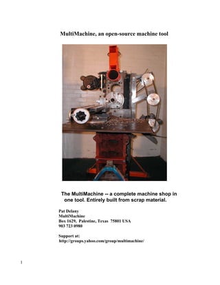
  • 1. MultiMachine, an open-source machine tool The MultiMachine -- a complete machine shop in one tool. Entirely built from scrap material. Pat Delany MultiMachine Box 1629, Palestine, Texas 75801 USA 903 723 0980 Support at: http://groups.yahoo.com/group/multimachine/ 1
  • 2. Introduction The MultiMachine is a multi purpose machine tool* that a semi-skilled mechanic with just regular hand tools can build using scrap car and truck parts. Electric power is not needed. In Developing Countries, the MultiMachine has the potential for saving or improving the lives of many thousands of people. These machines can be used in many ways: In the health sector by its use in building water pumps, filters, water well drilling rigs and hospital furnishings. In agriculture by its use in building farm machinery and irrigation pumps. In transportation by its use in building and repairing parts for vehicles. In communications by its use as as a cell phone charging station. In village life by being a source of battery power for home lighting. In education by providing vocational education students with machine tools that they build themselves and then are able to take back to their villages when they graduate. It could provide a local self supporting infrastructure that would be available to keep water and irrigation pumps in repair. Many NGOs go to great effort and expense to drill water wells and provide pumps in rural areas of underdeveloped countries. These pumps often fail because there is no person able to repair them. A small MultiMachine based business could provide a pump repairman with the means to earn a living in an area where these pumps and wells are used. The pump repairman could support himself by doing machine shop type jobs like making and sharpening agricultural tools and equipment and resurfacing vehicle flywheels, brake drums and disks. Machine tools often draw power intermittently from gas or diesel engines or electric motors. Any surplus power could run a welding machine built from a vehicle alternator and also recharge batteries that in turn could be used for home lighting or recharging cell phone batteries. The combination of a MultiMachine and a welder can be used to build different types of metal bending and rolling machines that can be used to manufacture fuel efficient cook stoves, pots, pans and similar products. The MultiMachine also provides a way to machine simple zinc and aluminum castings made from the metal found in old car parts. Without this machining, the castings are of limited use but simple machining can turn them into hundreds of different kinds of products. Vocational education takes "hands on" learning. Few vocational schools in developing countries have sufficient numbers of the machine tools that are necessary for training students. This is no problem with student built MultiMachines. * A machine tool is a powered mechanical device, typically used to fabricate metal components 2
  • 3. Look around you. Almost every manufactured product that is made of metal is a combination of parts that have been machined (castings, screws and bolts) and sheet, bar and tubular metal that has been welded, bent, rolled or spun into a needed shape. The essentialy free MultiMachine and the tools it can produce can do all this. A group of specialized MultiMachines can do much more. The MultiMachine can be easily built in dozens of special versions that are specially built to do just a single type of metal working job. If these special machines were grouped together and driven from a common power source, they could be used in a form of Developing World mass production. Most of these machine versions could be built with just one or two broken vehicle engines, a piece of pipe, a few feet of steel bar, a sack of cement and a few easily made zinc/aluminum castings. I am certain that MultiMachine newsgroup members will help adapt our designs to the types and sizes of material available in any community. Special thanks to George Ewen of “Engine Mill” fame, Jeff Hansen, Kevin Olson and to my craftsman friend, Frank Patterson. And a very special thanks to my wife, Clarissa, who put up with me during the four years this project took. 3
  • 4. Table of contents page 1 Cover 2 Introduction 4 Table of Contents 6 What the MultiMachine can do 10 5 construction techniques ( secrets) 1 Using engine blocks as building blocks 2 Boring the block to fit the bearing outside diameter 3 The spindle can be a piece of pipe the diameter of the bearing inside diameter 4 The use of a three bearing spindle 5 The engine blocks are clamped together with plate and keystock rather than dovetails 12 The machine is made of 5 modules that attach to a vehicle engine block 1 The vertical slide 2 The drive unit 3 Mounting the machine 4 The overarm 5 The spindle 13 About money, accuracy and skills 15 Tools 17 Construction starts The spindle in detail 22 Step 1, What do you want your machine to do? Step 2, Really learn the instructions! Step 3, Getting the stuff together. 24 Step 4, The machine and engine shops Step 5, When you get the blocks to your shop 25 Step 6, The MultiMachine needs something to sit on 26 Step 7, Modifying the block 29 Step 8, Mounting the block Step 9, Powering the machine 34 Step 10, The big plate that replaces very hard to make dovetails 38 Step 11, Mounting the big plate 39 Step 12, The vertical slide 43 Step 13, The cross slide 48 Step 14, The overarm 50 Step 15, Building your own “Broken bit” (tangential) cutting tools 52 Step 16, Building your own lathe chuck 4
  • 5. 53 Step 17, How to cut threads (the way it was done 90 years ago, it still works today) 54 How to build a really big MultiMachine 54 The ratchet drill 55 Two easy to build "temporary" lathes 57 The "giant" MultiMachine. 60 Pipe size chart 63 Morse taper chart 64 Metric bearing chart 66 Glossary 5
  • 6. The MultiMachine is a metal lathe that can be built to machine something as big as a manhole cover! It can face and cut tapers by simply rotating the cross feed on the “turntable.” It can drill and bore in many different ways It's an end mill It's a horizontal mill that can work well with really cheap eBay cutters! This resharpened cutter cost 75 cents! My MultiMachine made a 400rpm single pass-cut of .822” x 1/2” in this piece of 6061 aluminum. Other arbors can be easily made for fly cutters, wood and metal saw blades, surface grinding wheels and sanding drums and discs. 6
  • 7. How can the MultiMachine do all these things? In almost every kind of machining operation, either the work piece or the cutting tool turns. If enough flexibility is built into the parts of a machine tool involved in these functions, the resulting machine can do almost every kind of machining operation that will physically fit on it. You may have heard of 3-in-1 machine tools -- basically a combination of lathe, mill and drill press. The MultiMachine starts there but adds many other functions. It can be a 10- in-1 (or even more!) machine tool that is built by using vehicle engine blocks in a LEGO-like fashion. It can be built as a one-engine block machine with a plate and angle iron vertical slide. Or as a two-block version with an engine- block-based vertical slide. Or as a two-block-lathe-only version. (See the fixed lathe bed version below.) This is a three-block version with a fixed, long lathe bed and a rear-mounted vertical slide. Great if you have limited space! This version is similar to a Kitchen and Wade multipurpose machine (below) that was used aboard ships for many years -- a far more useful design for a machine tool than the common 3-in-1 machine. “ 7
  • 8. “Double-sided” MultiMachines (lathe on one side, all-function machine on the other) are perfect candidates for Variable Frequency Drives that make the machine spindles both variable speed and bi-directional. Pictured below is a four-block version with doubled vertical blocks mounted back to back so it can support a 4'-long spindle – useful with a heavy chuck. The machine can also have a rear vertical slide, and a 4- or 5-block version with a Bridgeport-like head could have an added horizontal block with powered spindle added on top. The most common size for a MultiMachine has 12-to-15" of table vertical travel and a 32" lathe “swing.” The horsepower required for regular lathe-type cutting tools makes them hard to use large work pieces. BUT...If you replace the cutting tool with a simple $30 bench grinder or even a homemade toolpost grinder, you can machine really big jobs. You can even resurface large clutch and brake parts for a truck. By using the simplest metal casting technique, a skill that has been around thousands of years, you can turn out products using machined aluminum alloy. It then becomes possible to build things like pump parts and to cast alloy bushings that could replace expensive ball bearings. One common alloy, ZA-12, contains about 12% aluminum, with zinc as most of the remainder. Both 8
  • 9. aluminum and zinc are materials commonly used in vehicles, making them easily available. ZA- 12 has a tensile strength approaching that of cast iron and is such a good bearing material that it is used for bushing-type bearings in steel-rolling mills. See the possibilities? 9
  • 10. The MultiMachine is extremely simple - basically 6 unusual construction techniques that we call “secrets” and 5 very simple “modules” that bolt to an engine block. Using engine blocks as building blocks is the first MultiMachine “secret.” Since cylinder bores are bored parallel to each other and at exact right angles to the cylinder head surface, MultiMachine accuracy begins at the factory where the engine block was built. The second MultiMachine secret! In the most common version of the MultiMachine, one that has a roller bearing spindle (the kind I built), this precision is maintained during construction with simple cylinder re-boring of the #3 cylinder to the size of the roller bearing outside diameter (OD) and re-boring the #1 cylinder to fit the overarm OD. The best part is that the cylinder-boring operations will probably cost less than $50. An engine machine shop provides the most inexpensive and accurate (.0005" on a 4" cylinder!) machine work commonly done anywhere and guarantees you that the spindle and overarm will be both aligned and at an exact right angle to the face (head surface) of the main engine block that serves as the base of the machine. The third MultiMachine “secret!” The spindle can be as simple as a piece of pipe machined to fit the inner diameter of the bearings. The fourth “secret” is the addition of a third bearing to the spindle. The three-bearing spindle is necessary because the “main” spindle bearings just “float” in the cylinder bore so that the third bearing is needed to “locate” the spindle, act as a thrust bearing, and support the heavy pulley. The fifth MultiMachine secret! The main engine block and the vertical-slide engine block fit together with the help of two 1/2" x 12" steel plates, along with my unique way of clamping the plates together. It's easily built, easily adjusted, and easily clamped into position without the workpiece moving. Far superior (I think!) to a homemade attempt at a four-foot-long dovetail. Long, angled cuts similar to this commercial dovetail assembly on the cross slide shown below would be far more difficult to build than the MultiMachine's simple, square sections that are bolted together. While the MultiMachine vertical slide requires only a drill to build, a long dovetail requires a very large milling machine. A hugely important difference! 10
  • 11. The use of smaller steel bar stock or angle iron may be necessary in some areas where the ½” x 12” steel plate may be hard to find. Pieces of truck frame rail could be used. Alignment of these “foundation” parts is critical, and substitutes for the preferred steel plate may be harder to adjust. Don't let the difficulty of making a sliding fit deter you from getting started. Build a fixed-bed lathe version first and later add a MultiMachine-type vertical slide to the rear of the block. Here is one kind of substitute that could work well: “doubled” frame walls that are common in big trucks. The rivets can be ground off and the two pieces made into a good sliding fit. The sixth MultiMachine secret is a device similar to this that can be clamped to a shaft. It can have capscrews that pass sideways in order to push or pull another device or can be made large enough to do dozens of jobs by itself. More about this later! 11
  • 12. The 5 simple modules that attach to the engine block: (1) The vertical slide module is basically a short engine block with a steel plate bolted to the head surface and a cross slide attached to to the end bell (upper) end. There are many kinds of cross slides that can be bought or built. If you have a little money to spend, think about buying a $69 ENCO one to use at first (in developing countries, however, a similar one may be the equivalent of a thousand dollars). Later, you can build something like a massive concrete and steel “Romig” single or twin lathe bed and cross slide. (See the “Romig” turret lathe design in the MultiMachine newsgroup “files” section.) J.V. Romig designed machine tools that were featured in Popular Mechanics magazine for almost thirty years. The designs still work well. This small cross slide also can be used for many other projects. Example: you can fit it on top of a turntable and use it for cutting tapers. (A turntable could also be fitted to the top of a big “Romig” bed to cut tapers.) (2) The drive unit module. There are literally dozens of ways to drive the machine. A combination of small and large pulleys makes a good medium-speed drive. Other setups might include multiple-groove pulleys or even the transmission from a lawn mower, garden cultivator, or pickup truck. Power can be provided by anything from an electrical appliance motor to a car or truck engine. (3) The machine mount module The quality of the finish your machine can make will be greatly affected by the rigidity and weight of the base. Since I lack work space, I had to have a machine that I could move around. Mine is built with an engine stand and mobile base. (A permanent base made from concrete or a heavy steel frame would be much more rigid.) An overhead hoist is a necessity since you'll be using a machine that may weigh well over a ton. If you decide to use an engine-stand-type machine mount, try to make it a one-ton model. In the USA, Harbor Freight has these for about a hundred dollars. 12
  • 13. (4) The overarm module may not even be needed by some people but others may see it as the heart of an entire tooling system. Because it is important that the overarm always stay in alignment, the #1 cylinder is re- bored to fit your overarm pipe at the same time the #3 cylinder is re-bored for the spindle. (5) The spindle module is the heart of the machine. No machine tool can do a proper job with an inaccurate spindle. Because the bearings actually run in the professionally bored cylinder bore of the engine block and the spindle is finish-machined on the MultiMachine itself, accuracy is achievable even by a novice machinist. (To be treated in much more detail later) Accuracy, money, tools and skills Your machine's accuracy is determined by the care you put into building it. There's no one checking your mistakes but you. Compounding a few barely-good-enough fits could make you end up with a machine that chatters too much to use. The chattering may be so severe that you can't even discover what causes it. Safety also depends on you. ALWAYS use protective guards on your machine. I can't stress it enough. Also...the MultiMachine is taller than it is wide, is very heavy, and is prone to fall over! Mine fell on me once and now I have a new, titanium knee! I liked the old one better. 13
  • 14. A little extra work lets you save a lot of money! I'm assuming that you would like to spend as little money as possible on this project. If you can afford to spend a lot, just search eBay and Craig's List for some of those wonderful machines left behind when US jobs went to China. When I built my MultiMachine, I tried to find ways to build it that could take almost no money and little or no electrical power either for building or operating it. I wanted a machine that could be built and run anywhere in the world – outdoors, in a shed without power, or in the finest workshop. The result is a machine that could be grouped with others like it to make a small factory. The machines could be powered by a single gas or diesel engine running an overhead shaft that is connected to them by simple pulleys and belts. You may have to learn a few new skills to build the machine, but these skills are also needed to make best use of the MultiMachine. Two important skills covered in many old machining books are grinding cutting tools to the correct shape and clamping work on a lathe faceplate. These kinds of subjects are also usually covered in just 20 or 30 pages in almost any of the older machining books that can be found in your local library, In our MultiMachine newsgroup or elsewhere on the web. The shape of the cutting tool is important in every lathe, milling and shaping/slotting machine operation. The tool has the same basic shape for many of these different operations. Learning the basics of grinding metal-cutting tools to the proper shape will save you lots of money. How to clamp work to a lathe faceplate is the other basic machining skill needed. There are many ways to do this that are described in older books. (See samples below.) Since three- and four-jaw chucks were not common for the first 80 or 90 years of wide metal-lathe usage, metal workers did without them. So can you if you have to. 14
  • 15. Incidentally--- The enlarged picture taken from the faceplate (shown on the right above) shows a wonderfully useful clamping device. To make it, just weld a short piece of threaded rod to the side of one of the long, coupling nuts commonly used to connect two pieces of threaded rod. Then add a bolt and a nut. It may help to grind a slight angle on the coupling nut so that the screw forces the work- piece into the face plate. That's all it takes! Knowing how to cast aluminum alloy is vital to building a really cheap (or almost free) MultiMachine. Cast aluminum alloy parts can replace expensive bearings, spacers, adjusters and pulleys in your machine. Since you don't need fancy pattern-making for the MultiMachine, casting for it is simple. You can just cast round sections and turn them into the parts you need by using one of the “temporary” lathe designs found at the end of this booklet. These cast parts let you adapt junk-priced pipes and shafts to the sizes you need so you can avoid buying new stuff at retail prices. Tools you will need For those who don't have a power drill (or power), see the end of this booklet for a way to build a ratchet drill. If you have only a pistol-type electrical drill, you should buy or make some kind of stand for it. If you have a small, bench drill press that can be made to run at slow speed (by changing pulleys?), turn the head around and clamp the stand to the work. If you have a big drill press, lower the head almost to the ground and make a ground-level 2x4 and plywood table to put your work on. This provides a safe way to drill holes in 120-pound pieces of steel. For large holes, just "step" drill (start with a small drill bit and work up an eighth of an inch at a time.) A hacksaw (and a bunch of high-quality blades such as the 43-cent Starrett ones from ENCO) will work for sawing. If you don't have a electric grinder, you can use a hammer, chisel, file, and a hand cranked grinder (for grinding cutting tools) as mechanics did for hundreds of years. I was serious when I said only basic tools were needed but I need to add three kinds of more unusual tools that some mechanics won't have. One of these is a set of transfer punches. A set of these will usually cost under ten dollars. Transfer screws (one half inch long pieces of threaded rod with a point ground on one end) are extremely useful in machine building. A mechanic should be able to make both these tools The third tool is a dial indicator that also is usually under ten dollars. The dial indicator is needed for checking spindle and elevating table adjustments. 15
  • 16. Transfer screws Transfer punches Dial indicator You can weld some of the machine parts that don't have to be in perfect alignment. Your welding setup can be as simple as connecting 2 or 3 car batteries in series (positive on one to negative on the next) by using long jumper cables and keeping the welding job a safe way from the batteries. Carefully protect the batteries from any welding spark! Don't weld anything that can have the slightest effect on machine alignment! The fastest way to ruin any machine tool is to weld it Two things to keep in mind when reading this booklet: I am an inventor and not a precision machinist (or precision anything else!) or an engineer. Take everything I say as my personal experience and nothing more. 16
  • 17. Safety again... Every machinery book or video stresses safety, and well they should. Lifting and drilling accurate holes in the MultiMachine's big, heavy parts requires a lot of thought. THINK! Measure everything several times and work on heavy stuff as close to the ground as possible. A slippery, hundred-pound piece of oily steel on top of a steel table can be very dangerous. Construction starts! Construction should be almost foolproof. In the final chapter I'll tell how to build an even bigger (may weigh five or more tons) MultiMachine that can be built with no store bought stuff at all! It also can be built by using only hand tools and no electric power. How to build a “middle” size roller bearing version that is based on easily available car and light truck engine blocks. Middle sized or not, this is no toy since just the spindle assembly, bearings, chuck and pulley may easily weigh well over 130 pounds and the whole machine may weigh over half a ton. The Spindle in detail Let's start with the spindle since it is the heart of the machine and there are many ways it can be built. Each of these different ways affects the way the rest of the machine is built. Look carefully at the roller bearing spindle picture and you will realize that the spindle works just like a bicycle front axle with just three small differences. The big spacer that separates the bearings, the way the bearings are adjusted and the third spindle bearing that functions both as a thrust bearing and to support for the weight of a heavy pulley. But first lets talk about spindle and bearing size so that you can keep these things in mind when we study the individual parts. The maximum spindle size is closely related to the bore size of your engine block and also to what is the machine going to be used for. If the MultiMachine is going to be used in a model makers shop, a small 6 cylinder block with a bore of 3.5” to 3.6" would be fine. Chuck thread size would probably be the very common 1 1/2" 8 and the spindle would have a bore of about 1". One similar to the one I ended up with would probably have cylinder bore of 3 7/8 or 4" ( This 1/8" difference can be very important because the smaller bore can just be re-bored without needing to be sleeved. It can easily have the very useful spindle chuck thread size of 2 1/4" 8 (like the South Bend heavy 10 lathe) and would also have 1 3/4" spindle bore. This is a much more useful machine than one just that is just slightly smaller because having the largest possible 17
  • 18. spindle bore size is very important. Modern lathes do not usually have long beds and a long bed is especially difficult to have on a conventional MultiMachine since the vertical slide would have to be deep (long) enough to support the bed. A long bed like this could be difficult to raise evenly. Modern lathes feed the work through large (or giant) spindle bores like one on our largest MultiMachine designs. Strangely enough the 100 year old Lindsay book "Practical Metal Turning" talks about just this as the "modern" way! I would choose one of the common Chevrolet, Jeep or similar straight 6 cylinder engines with a 3 7/8" bore. I would use 100 mm OD bearings and bore the block to that size. (3.937"). For a spindle I would use a 20" piece of 2 1/2" xxhy pipe (a pipe size chart is at the end of the book) that has an OD of 2.875” and an ID of 1.771. This would allow plenty of room for a 2 1/4" 8 thread and the shoulder and register that the chuck “centers” on when it is mounted. Simple so far. The reason for the metric bearing size is because they seem to cost a lot less. I used 4 1/8" OD Timken bearings in my 6 cylinder Ford 300 cubic inch pickup block and the cheapest roller bearings I could find were $75 ea, I later found metric 100mm 32013x and 32011 bearings for $22 to $32 (probably different quality). These bearings have an ID of 65mm and 55mm respectively which is perfect for this size pipe. It also means that the spindle can be threaded (use a dial indicator to center the spindle thread on the bore) and room left for the "register", shoulder and bearings. The #1 cylinder can be bored to the size of a "cleaned up" piece of 4" OD pipe or tubing that is used for the overarm. Like everywhere, there are trade offs here, and in this case it is that "x" at the end of the 32013x bearing number. This is not a heavy duty bearing even though it is supposedly rated for automotive use. If we would go to a heavier duty bearing (32011) with a 55mm or 2.165” ID then the spindle wall is just .2" thick which seems thin but will probably work fine. Nothing is written in stone in this project, a clean 100mm cylinder bore gives you many choices in spindles that use single or double ball bearings, tapered roller bearings (like mine) or cast aluminum alloy bushings. If you spend a nice afternoon at your NAPA dealer, you will probably be able to find inexpensive bearings to fit almost any block within a 3.75” to 4.25” range of bore sizes. So what to use if you are totally broke or stuck a hundred miles from nowhere in Kenya? No problem! Just build our ratchet drill and one of the “temporary” lathes described at the end of this booklet, cast bushings or take apart every front and back axle that you can find to harvest the bearings, pile these and whatever pipe pieces that you can find under a good shade tree and sit down and think! MultiMachines are thinking peoples tools. I guarantee you will find a way since there are dozens of ways to build the spindle (and almost everything else here)! Lets start from the front end of the spindle to keep things in some kind of order. I am going to assume that you have a way to thread the spindle but if you don't, no problem again! You will soon learn about our “miracle” device that can cure almost every problem! It can mount a big chuck on one end of an un-threaded spindle, be a roller bearing adjuster, a thrust bearing, a pulley mount or a mounted pulley and also clamp all kinds of attachments to the back end of the spindle. But first, what size pipe to use for the spindle? It could be almost any size! But since we have to 18
  • 19. start somewhere I am going to assume you chose to use the size of pipe I recommended above (and found, which may be hard in some places ). (pipe chart at end of this booklet) This picture (below) shows the critical spindle “nose” that you would thread 2 1/4” 8 threads per inch to match a chuck backplate. NEXT comes the important part! Look carefully at the little section between the thread and the spindle shoulder. It is called the “register”. The register area centers the backplate on the spindle when the backplate is screwed on far enough to hit the spindle shoulder. This is extremely important since it means that the spindle can be threaded on another lathe and still be accurate on your MultiMachine. After you get your machine powered up and the bearings adjusted, take light cuts on the register and shoulder surfaces until the chuck backplate is a “wringing” (gently screwing the backplate forwards and backwards until it works it's way over the register) fit. The chuck backplate will then be a custom fit on the MultiMachine itself. The spindle threads don't center the chuck, the register and shoulder do! After this careful fitting is done, take a cut (machine the surface) on the chuck backplate to make sure it is running true before you bolt on the chuck. The MultiMachine newsgroup “files” section has an excellent article about mounting chucks. How long should this shoulder be? In this case, at least an inch and a quarter. If you eventually want to be able to cut threads, add another inch to this for a timing gear pulley that will drive a thread follower device that is currently being developed. Remember that a 1/2” plate bolts to the front of the block and that you will need additional shoulder space for set screws etc. After the shoulder comes the space for the front roller bearing. The big spacer between the bearings takes the place of the bicycle hub and must be carefully made and and fitted so that the roller bearings are absolutely parallel. The spindle can be slightly undercut the same length of the spacer to make it easier to press the front bearing on. The inner roller bearing should be a slightly (polish with emery cloth) looser fit on the spindle to make it easier to to adjust. If you over-tighten this bearing then slightly back off the adjustment screws, run the machine and let it “shake” lose a little. The adjuster is the really BIG MultiMachine secret! It is not the usual nut on a threaded spindle. It is a combination of two common industrial devices. Dave Gingery used the idea on his horizontal milling machine arbor and I added the clamp bolts to avoid having to pock mark the spindle with set screw marks. This design is a wonderful idea that can be used many times in 19
  • 20. machine construction and also in building necessary tooling. This is an early adjuster design, a better one would also have clamp bolts like the designs on the right and below. A hub with twin clamp bolts would be even better. 20
  • 21. The Gingery horizontal mill arbor. I would replace the three setscrews that position the fixed collars with just one setscrew and a clamp bolt (or bolts) like the horizontal mill cutter. If you don't already own the Gingery casting and cast machine tool books, buy them! Combining the power of the MultiMachine with skills that you learn from building the Gingery tools will let you build almost anything! I mentioned the third bearing earlier. It locates the whole spindle assembly. It serves as a thrust bearing which is necessary with the roller bearing spindle because these bearings just "float" in the cylinder bore and it also supports the drive pulley. This pulley may weigh 20 to 30 pounds and be 10" out from the inner roller bearing so additional support is vital. Three bearing spindles are unusual because of possible alignment problems, we will cover our easy solution to this a little farther along. The thrust bearing/bushing can be as simple as a cast sleeve with a shoulder that would bolt to the main bearing pads and two thin versions of our “adjusters” clamped to the spindle. Now... something I consider very important. Everybody will want to put his own "stamp" on his machine. Think carefully before you do it here. The spindle MUST be centered on the cylinder bore because this lets you align the lathe bed or cross slide with the block cylinder head surface. Trying to align machine parts by using the short piece of spindle that sticks out from the main block is almost impossible. Think carefully before you change something here. Think ease of re-alignment FIRST! The table can go up and down 16" or more and the cross feed may be able to rotate 360 degrees but all this will be wasted if the table and cross slide has to stay locked in place because they are simply too hard to re-align! Another extraneous but very important thought! The size and weight of the MultiMachine really do matter! In the late 1800's the vertical slide alone on a similar capacity horizontal milling machine commonly weighed 3000 lbs. In the early 1900's Cincinnati, the great American milling machine company increased the weight of their machine bases by over 600% when they found that under heavy cuts the cast iron bases were flexing like drum heads. Today 2 or 3hp Bridgeport milling machines weigh over 2400 pounds for a good reason. Your MultiMachine may weigh only a third of this so always keep in mind the importance of using sheer mass to suppress vibration.. Concrete is your friend, when you get your machine to work like it should then fill the base of the main block and also the vertical slide with polymer concrete mix. 21
  • 22. The most important rule for building anything! (I think)! "Pay infinite attention to detail" This is an old Mercedes Benz racing team slogan. Work as carefully as you can. A careless fit will cause "chattering" (cutter vibration) that may take months to diagnose! Several careless fits will compound the errors. Because of the flexibility of the MultiMachine you will eventually try things that are almost impossible! Give the machine a chance! So... to work! Step 1, What do you want your machine to do? What kinds of machining jobs are likely to come up in the future? Should it be able to make models or oil field tools. Should it weigh 100 lbs or 150 times that much. The smallest and largest machines can be built in almost the same way and in each case there are interrelated choices between things like cylinder size, spindle size, spindle bore size and bearing and chuck type and size. Remember that a vertical slide that is meant to be raised and lowered is not going to be long enough or wide enough for some kinds of jobs (of course no lathe is long enough for some jobs!). The MultiMachine can make up for this by having a huge bore in the spindle for the workpiece to pass through. Most modern lathes work this way but few have a 4.8" or larger bore size that is easy to get on a MultiMachine that is based on a Dodge/Cummins pickup engine block. Every design decision involves trade offs. A really big spindle and chuck in a relatively light MultiMachine will only work at low spindle speeds. High speed sawing and grinding will be almost impossible without careful and expensive balancing. Step 2, Really learn the instructions! Unless you have a lot of money to waste, don't begin construction until you have thought out every tiny detail of how the parts will fit together. Having to build a machine twice makes it cost twice as much and worse than that, may relegate it to your unfinished project pile! As far as I know no machine tool is built using engine blocks like LEGO and no machine tool uses a 3 bearing spindle in this way. Sit back, think everything through. Know where every single part is going to come from and that includes every bolt and nut! The extra extra heavy walled pipe that is used for the spindle may be common in one area but hard to find in another. You may have to redesign your whole machine if one component can't be found. Be sure to know the exact size and condition of your chosen engine block bore and to what size it can be re-bored to for our purposes (not to hold water). Step 3, Getting the stuff together. You obviously have to have planned every detail first. This is what would be needed for a conventional two engine block version. (1) The "big" 6 cylinder engine block, this can be anything from a Mercury 6 cylinder outboard block for an apartment sized MultiMachine to a 10+ foot long industrial engine block. For these instructions I'm going to assume a size common in the USA, a 3 7/8" bore 6 cylinder engine block. Similar sizes have been used for trucks in many other places. The first place to look for 22
  • 23. engine blocks is in the junk pile behind engine shops. These usually have the big advantage of being de-greased! You will need a smaller cast iron block for the vertical slide. Well, not exactly at this stage but you will need it when assembly first begins and it is easier to search for it while you are searching for the “big” block. What ever you choose, it needs to be as short and heavy as possible. An iron V6 will probably work fine or look for a very common small Dodge D50 truck four cylinder block. I've used everything from a Model A Ford to a Volvo turbo block. (2) 4' of 4" OD "round" (if possible, most is not truly round) pipe for the over arm. Remember that the overarm may not be needed for some machines but is critical for others. At the very least, make the #1 cylinder bore able to be retro-fitted to an available size of pipe without having to take the entire machine apart to have it re-bored later. (3) A 20?" long piece of extra-extra heavy wall 2 1/2" xxhw pipe or a similar sized hollow bar to use for the spindle. The length of course depends on the size of the engine block that you use. Try to leave at least three extra inches of spindle outboard of the pulley. Different kinds of tooling like a traveling head boring bar may need this space. Try not to settle for less than a 1 3/4" spindle bore on a short bed lathe that is to be used for a wide range of projects. (4) 2 roller bearings and a flange or home cast thrust bearing The roller bearings could be anywhere from about 2 1/8" to 2 ¾" ID (assuming 2 1/2" xxhw pipe) and between 3 7/8" and 4 1/8" OD. The flange bearing (third spindle bearing) bore could be a little smaller than the roller bearing IDs and the pulley bored slightly smaller still. Think seriously about using those Metric 100 mm spindle bearings. (5) A threaded chuck or back plate to test the spindle thread if you are going to use a threaded spindle. (6) A 1 1/2”" slice of 3-1/2" steel shaft or a similar sized ZA-12 casting that can be bored to fit the spindle. It will be needed for the bearing adjuster. Get at least 6 extra two inch "slices" for horizontal mill arbors, boring heads, fly cutters, thrust bearings etc. (7) A 2" washer for the floating part of the adjuster. (8) A 1 or 2 groove 12" OD pulley that can be adapted to fit the end of the spindle. (9) An approx. 6" long piece of 3 1/2" pipe to make into a separator for the roller bearings. Important, length is bore length less the width of the bearings. This spacer "floats in the cylinder so it should be just a few thousandth of an inch smaller than the bore, use shim stock and Locktite to make a snug fit because a loose fit can be the source of strange noises. Ends must be accurately machined or the bearings will slightly "cock" and cause great trouble! The spindle can be slightly undercut in the area underneath this spacer to make it easier to press on the front bearing. . (10) Used head gaskets for both blocks. (an easy way to mark holes but not absolutely necessary) 23
  • 24. Every one of those parts should be on hand when you start the fitting process. Step 4, The machine and engine shops The engine shop bores and/or sleeves the block to fit the bearing and overarm outside dimensions. Simple enough, but if for some reason this boring is not possible and the cylinder bores are not badly worn then simple sleeve type bearing adapters could be made. Remember there is the potential of a loss in accuracy with each bearing adapter you use so be very careful here. The spindle is the heart of the machine and is not a good place to make shortcuts. If you do have to use bearing adapters, all you may really need is the very top and bottom end of the of the cylinder to be true and unworn. Step 5, When you get the blocks to your shop It is important to find out how they fit together. Mzny combinations of blocks will work but now is the time to find out exactly how. The blocks should be carefully tested to see how they fit together. Lay the big block on it's back. Lay on a piece of the steel bar than you plan to use or an identically sized piece of plywood and then lay the small block face down on top of the main block. Check for clearance for the clamps that hold the blocks together. Try to get at the very least 2" clearance on each side. To help get this clearance, protrusions may have to be ground off and either the plate or the small block that is used for the vertical slide may have to be offset to one side. Step 6, The MultiMachine needs something to sit on Concrete is always best, two steel tables or frames that would isolate the power unit from the MultiMachine would be almost as good but mine had to roll around so I chose to modify a store bought engine stand. It has worked very well even though it tends to rock back and forth under a heavy cut. One inch jack screws on each corner would be a good idea. Just burn holes in each corner of the stand, weld on nuts and use bolts or allthread to slightly raise and level each corner. 24
  • 25. The completed engine stand It bolts to the engine main bearing pads instead of the end bell. The vertical post should be cut at the point where it connects to the horizontal frame and re-welded so that it will be in a truly vertical position. The post has had 3 diagonal braces added. 1” pipe would be best here. the front brace must stick out no more than the normal height of the block or it will interfere with the big plate that bolts to the front of the block. It's had a "crane" added. Don't mount your “crane” like this! The 1 1/4 pipe base of the 1" crane pipe should really be mounted as low as possible on the square tube that the wheels are attached to. The bottom crane support should allow the base of the crane to rest on he floor. The mount should also stick out at least 1 1/2 " more than is shown in this picture.. 25
  • 26. Drill at the circled position, weld on a 3/8” nut for a clamp bolt so that the crane won't swing under load. If you have to work in a spot with a low ceiling, the top support should be removable. I found out this when the crane was in the way of something I was trying to do. I tried to use the crane to hold up the block, power unit and vertical slide plate. Big mistake! the crane tried to swing the load behind the engine stand, knocked me through a big window. Add 1” jack screws at each corner or take the wheels off and back it up against a wall if you are going to try something with the slightest risk! The original mounting plate was notched with a grinder and lined up perfectly with the main bearing bolt holes. Step 7, Modifying the block Boring the block to fit the overarm and the spindle was the first step in block modifications. Grinding extraneous bits off is next. First, one important point, grinding cast iron is not a clean process, try to do it outside if possible. Also, be very careful with safety here, I had iron particles bounce off my face and get under both a face shield and safety glasses and then ended up in my eyes. Have lots of filtered water or eyewash easily available. I have used quarts of “eye wash” that was just filtered water from my refrigerator on this project 26
  • 27. Grind away anything that is going to get in the way of the overarm and the spindle since they need to pass all the way through the block. No grinder? Use a smaller chisel to to make small notches along a line that marks what you want to remove and then use a bigger chisel to chip away the excess up to that line. I have already mentioned the different kinds of bearings that can be used in the cylinder bore, There are lots of choices for thrust bearing also. The block modifications are about the same for whatever bearing you choose. Be certain to check for clearance so that the spindle assembly can be inserted from the rear. Also check for clearance around the main bearing bolt holes so that the thrust bearing can be bolted to the main bearing pads. A round flange type bearing that can fit into the main bearing pads works with spindles up to about 1 15/16” in diameter. In the USA, Surplus Center often has these for about $20. Special note....Import flange bearings seem to be of very uneven quality. I originally used a LinkBelt flange bearing on the front end of the spindle (as shown in some of the pictures) but quit when the next one I bought was too loose to use. If you buy one for the pulley end of the spindle, be sure to check it out before you install it. Premium USA made flange bearings may be far too expensive to use. This was what was cut away for the round Linkbelt bearing. 27
  • 28. You can easily see that a really large pipe spindle thrust bearing is just not going to fit on the main bearing pads even with some kind of adapter. Incidentally the one shown here should have the ends marked with tape cut off. One alternative would be to not mount the bearing on the main bearing pad at all but instead use a large adapter plate that would mount on the flange that the oil pan normally attaches to. Bigger bolts would probably be needed and there may not be room for them however. The best (and by far cheapest!) way would be to cast a simple bearing/bushing out of ZA-12. The cast bushing could be a simple bushing with a flange that would bolt to the main bearing pads. You could use two of our clamp type collars (adjusters) on the spindle. Bronze rings should be used between the ZA-12 parts but there is probably no rush for this if you are careful to keep every thing well oiled. Two important points about this thrust bushing. Before the thrust bearing is installed, install the pulley and run the spindle with very little belt tension for a few hours as you adjust the bearing adjuster. Let everything wear in until the spindle turns freely and yet has no measurable play shown on a dial indicator. Fit the bushing then and mark the flange bolt holes with transfer screws. Drill the flange bolt holes with no clearance for the mounting bolts and bolt the flange up evenly. This will insure that all three bearings are in alignment. 28
  • 29. Is the support plate that I put between the block and the engine stand mount really necessary? Probably not if the big front plate goes to the top of the block. These were the only block modifications I needed for the support plate. I only had to grind off about one sixteenth inch off the edge of the main bearing pads. Look carefully at the main bearing bolt holes and you will see the transfer screws I used here. One more thing, the engine stand motor mount adapter wasn't meant to bolt to main bearing pads so grind off anything that gets in the way! Necessary changes to the front of the block? You found out what was needed when you first fitted the blocks together. Now is the time to get any grinding done. In my case it actually took very little. 29
  • 30. Step 8, Mounting the block The crane is great for lifting heavy tools and workpieces, picking up the block like this was simple. Step 9, Powering the machine If a steel or concrete table is to be used for MultiMachine, make certain that it is wide enough to have a two foot space off to one side to use for the drive unit. If possible give the drive it's own table since that is a good way to suppress vibration. If the drive is to be attached to the side of the block then it is easier to build it while the engine block is turned on its side. Be careful here because the heavy swinging electric motor is very hard to handle. The motor and its mount can be dangerous. If you plan to use the machine only as a horizontal mill used for milling iron or steel then a single 50 to 100 rpm speed range is needed but may take six 2 grove pulleys. If you want a very useful, simple general purpose lathe, end mill and drill then a single 450 rpm speed is a good choice. I have found that this speed also works well on aluminum with a three or four inch horizontal milling cutter. Use three inch and twelve inch two grove pulleys to get this speed. Grizzly tools has some very nice cast iron pulleys that will work here. Why two groove? Three groove pulleys with matched belts would be even better but are much more expensive and also are also hard to find. Getting a 100+ lb. spindle up to speed with a 2+ hp motor causes a lot of noisy belt slipping with just a single belt. If you try to use cheap zinc hardware store pulleys you may find that they soon fly apart! For more reduction, fit in a small truck transmission that has an extra low first gear. The best but $300 answer is a VFD (variable frequency drive) 3hp motor and a 2 speed (4 pulley) belt arrangement. This could give you a high range of 300 to 3000 rpm and a low range of 50 to 500 rpm. The MultiMachine idea is to do everything as cheaply as possible so this goes against the grain a little but if you have money to spend, this is a good place for it to go. After thinking about all this, the single 450rpm speed may sound better and better! A warning about belt drives and aluminum pulleys. For many years I worked on large industrial belt drives that used iron pulleys and never noticed a friction problem. However, just slightly increasing belt tension with the multiple aluminum pulleys will make my machine bog completely down to a stop. This is another reason to start with a single 450rpm speed. 30
  • 31. Again... only mount the power unit on the MultiMachine if the machine needs to be movable. Vibration makes machining a smooth surface difficult. A mechanically isolated motor and speed reducer is the best way to reduce vibration. There are almost unlimited ways to power the machine but no matter how you plan to power your machine, you will probably need a mounting plate like this one that I made from scrap. It is securely bolted to the side of the block. Make it as long and wide as possible and use 1/4" plate if possible. I used 3/16" and it tended to flex under load. On the plate I used, the bottom holes were marked with transfer screws and the top holes were “guestimated” because I did not have the right size transfer screws. Big mistake! Do it right the first time! If the tapped hole is not level with the others then use a short piece of allthread, a nut half screwed on and then the transfer screw screwed into the rest of the nut. Unless you are very experienced at such things don't try to estimate the hole location. I welded on 2 pieces of bed rail to use to mount the motor and pulleys. His was a bad choice. There is too much flexibility in the kind of steel used for bed rails. I should have used heavier angle iron rails mounted farther apart. Carefully lay everything out first. Don't forget that belts can be changed by unbolting rails and pillow blocks so mount the angle iron rails close to the plate edges. Any "twisting" of the mounts will cause belt slippage when the motor brings the heavy chuck up to speed. A 2, 3 or 5 hp motor accelerating a 40 lb chuck from a dead stop is going to put serious force on the pulleys and mounts. The notch on the bottom right of the plate is there for clearance for the clamp bolts on the vertical slide. Here the plate is shown bolted to the side of the block. 31
  • 32. An earlier picture showed the whole finished motor mount made with slotted bed rails. Slotted bed rail pieces can work well work well only if they are welded to heavy angle iron. This pipe handle was added for more than ease of speed changing, it really cut down on twisting of the assembly under load. All the pulley brackets should have these pipe handles for this reason! Don't forget that the motor electrical connection box can get in the way if plenty of room is not left for it. Again, it would be best if the pulleys were mounted inboard the mounting rails if possible. Be sure to lay everything out first so you can be sure the motor and pulley assemblies all fit properly. Work carefully here and you will get a quiet, powerful machine that is less likely to "chatter". The intermediate pulley bracket. This is what I call the final drive bracket. It should be made out of one foot long heavy angle iron and as wide as possible. Add a pipe handle at the top to make it more rigid and easier to adjust. I reinforced this one several times and it still twisted. Here is the final drive adjuster. Pretty crude but like I said before, I am an inventor not a 32
  • 33. craftsman. Best use two of these, one on each side rail. If you separate the power unit from the block you will probably mount the assembly on it's back and you won't have gravity to keep the belts tight and you will definitely need 2 adjusters on the motor and two each on the pulley brackets also. More top pulley pictures 33
  • 34. The back of the machine. Incidentally the second motor is used to drive the spindle at a single 3000 rpm speed. It is cheaper and more efficient to do it this way than trying to use multiple pulleys get a 100 to 3000 rpm speed range. When this speed is needed for a grinder or chop saw, the spindle pulley is replaced with a smaller one that is slightly larger than the motor pulley. 34
  • 35. Step 10, The big plate If you have already bored the block and finished the spindle there is really just one big job left (assuming that you buy a cross slide), measuring, cutting and drilling the plates that bolt to the engine block head surfaces. A 1/2” x 12” plate is obviously is what I used but it is not for everybody. It was the easiest way for me but such a steel size may not even be available or affordable in many parts of the world What else could you use? How about two parallel pieces of bar stock. Two nominally six inch wide pieces should be about twelve inches wide. The exact width is not as important as having the outside edges absolutely parallel. Use a metal scraper or file to adjust if necessary Angle iron could also be made to work. Two pieces of large angle iron would be needed for each engine block. Since we use both the inner and outer sides of the angle iron, the iron may have to be the lighter grade that has parallel instead of tapered sides. Four pieces of vehicle frame rail will often be the “Developing World” solution. One of the best ways came from Jeff Hansen of the Yahoo MultiMachine newsgroup. The "doubled" frame pieces (shown earlier) from a big truck. Cut them apart and lap them together (with sand?) for a good sliding fit By now you have probably realized that I can't tell you how long this plate should be because I don't know how long your block will be since you can use an engine block from a Mercury outboard, a big industrial engine or anything in between. The first thing to do is to lift the block into place and to measure how high you want the plate to go up on the block. Mine only went half way up because I was afraid of warping the plate by burning a hole in it for the spindle. My fears were groundless because later burning experiments did not warp the plate at all. If I did it again I would extend the plate to the very top of the block and burn holes for the the spindle and the overarm. Why so long? The more mounting bolts the better. Your MultiMachine may be used for many different kinds of work in the future. You may install a slotter/shaper in the #2 cylinder. You may even add an additional horizontal block to the top of your machine for a vertical “Bridgeport” like spindle. 35
  • 36. You may also use the #1 cylinder for the spindle if you don't need your machine to be a horizontal mill that would normally use this cylinder for the overarm. eBay makes horizontal mills extremely useful because of the cutters often being available at 95% discount. Even if you don't have access to cheap cutters, a homemade fly cutter is much easier to make than a homemade end mill. If the block is mounted on a concrete pedestal, the plate could even go down into a pit and then the top of the vertical slide could be as low as floor level. This photograph shows how I did it on my engine stand version. I used a piece of 1/2" x 12” for the baseplate and found that it was useful for suppressing vibration. A close fit here will also suppress vibration. You also should use a heavier thickness of angle iron than I did. When in doubt about which metal thickness to use, always select the heaviest plate or angle that is practical. Countersink the holes and use flat head cap screws in the angle iron. Regular hex head bolts always seem to get in the way here. 36
  • 37. The base plate was attached to the engine stand using a simple clamp like this. Important points to remember about the big plate Flat head 7/16" screws and flat head metric screws are often hard to find. In the USA, McMaster-Carr has them in small lots. For a totally poor boy way to attach the plate, mark the holes very carefully and drill to the exact size of cheap bolts, counter sink the holes you drilled in the plate, saw the studs off a little long and peen (hammer) the excess into the counter sinks. A heating torch would help here but it is not vital if you work carefully and use low quality (softer) bolts instead of high strength head bolts. Don't use the end of a plate that has been sheared (chopped off at the steel mill). Shearing is going to distort the end so that it will be difficult to use for our purposes. Hot rolled plate is often not truly flat. This causes no problem with the MultiMachine. The important thing to remember is that the outer edges and not the center of the two plates make contact. If there is just center contact the table will be able to rock sideways when making a heavy cut. This will cause the machine to chatter. Face the plates so that the edges touch and make these contact areas as smooth as possible. A good way to do this is to carefully degrease the plate and then use a flap type sanding disc on it. This will probably work well enough so that lapping the plates together won't be necessary. To mark the holes in the plate, put a transfer screw in the top head bolt stud hole you're going to use and also in the bottom one. Measure exactly the distance between the top of the transfer screw point and the bottom transfer screw point. What I actually did was to lay a thin Aluminum bar across the top and bottom transfer screws and lightly tapped to mark the positions. I drilled through these marks with a very small bit to mark the top and bottom hole positions. I located the top hole position on the big plate and center punched it then dragged (picture below) that measurement down to about where the bottom hole would be.. I scribed a line and then used the aluminum bar with the tiny holes in it to mark the position of the second hole. Check everything again and center punch and drill a shallow 1/8" hole. The easy way to mark the remaining holes is to use a head gasket and a transfer punch. If you don't have a head gasket 37
  • 38. or want a more accurate method, then with the block on its back turn the plate over so that the punched and drilled holes face the block and slide the center punched and drilled holes over first two transfer screw points. One reason for drilling the center punch marks is that you have to feel the “clicks” when the transfer screws “fall” into the marked and drilled holes. Keep inserting one transfer screw at a time to mark the rest of the the holes. When marking these holes be sure to keep your brain in gear so that you punch the right side of the plate. The vertical slide plate is done in the same way. Don't forget that many other holes have to be drilled and tapped in the plates for the clamp mechanism. Don't use heavy grease between the plates when you assemble the machine. Cool weather will make the grease too sticky and this makes it difficult to raise the vertical slide in small increments. If all of this seems a little “jackleg”, it probably is but it works extremely well! Very important! Where should you mount the jack on your machine? I really don't know! My outboard jack works beautifully except when I try lower the vertical slide a small amount. I often have to lower it a bit too far and then raise it again to the exact height. The dial indicator is vital here. What should you do? Most “knee” type milling machines have a large acme threaded screw about two thirds of the way out from the inner edge of the vertical slide. It is more complicated on a MultiMachine because the very heavy bed and carriage will probably be offset to the left (facing the machine) side. I suggest you try a small jack such as a scissors jack, weld some kind of a plate on top so that the top of the jack will not fall in a “hole” in the end of the short engine block and try different jack positions until you find the best one. 38
  • 39. Step 11, Mounting the big plate Mounting the plate to the face of the big block is simple but requires great care. Turn the block so that it is in its normal vertical position and line up the holes carefully, don't cross thread! Don't drop on foot! Your plate could weigh over 120 lbs. If you use a short plate or need additional reinforcement then put a long coupling nut on the center screws, attach pieces of all thread and add the reinforcing plate on the main bearing pads at the rear of the block. Step 12, The vertical slide Use almost any short and heavy engine block as the core of the vertical slide. Mark and drill the 1/2” x 12” plate the same way as the plate for the large block. I used an old head gasket to mark the holes. Again...remember that many tapped holes for the clamp mechanism needed to be added to both plates. Think ahead! The “first” vertical slide clamp This clamp actually worked well when I used a worn hacksaw blade as a “gib”. 39
  • 40. Later I replaced that clamp with this one so that the contact surfaces were only made with smoother and more accurate pieces of three quarter and one inch cold rolled key stock. The drawings on the next two pages show the current clamp mechanism. By properly adjusting the top and bottom 3/4” clamp bolts (putting a little more pressure on the bottom clamp bolt than on the top) and adding a little pressure with the jack, the vertical slide can be raised in increments of .0001” (by light taps!) and the table does not move when the clamp bolts are tightened! 40
  • 41. 41
  • 42. 42
  • 43. Step 13, The vertical slide turntable and cross slide Bigger is better so try for a two foot square table. The removable machine table top can be a wonderful tool itself. Unlike a store bought tool, you can (with good conscience!) drill and mount holding fixtures and adapters for the cross feed table. When it looks like a swiss cheese, just call it "versatile". When you mount the top plate to the vertical slide block you probably need to use both transfer punches and transfer screws to properly mark all of the holes. Be sure that there is a 3/4" hole in the center of the plate that will let you turn a commercial cross slide 360 degrees. A “Romig” bed and cross slide will probably be too long to turn. Drill at least two more holes for alternate slide positions. I chose one that was even with the first hole and 6" toward the left as you face the machine and also one closer to the chuck so that the tool post would be close to the center of the cross slide for heavy cuts. Don't forget clearance room for the nuts. Be certain that a cutting tool can cut from the center of the spindle to the edge of the largest faceplate that you are going to use. This is the smallest of the common commercially available cross slide tables. $70 in the US but might be many times that much in other countries If you use a “store bought” cross slide then mount it on a turntable. The turntable can serve as a lathe compound. If you make the turntable 11.46 inches in diameter then a 36" length of 1/4" tape measure will give you 360 degree graduations at one and a quarter degrees each! Be sure to check for clearance for bottom cross feed knob. You may have to add a spacer for clearance. 43
  • 44. Building your own cross slide The original “Romig” turret lathe cross slide (above). Our version (below) clamps the carriage down with a weight along with screwed together pieces of key stock while this much earlier design used pieces of angle iron. What you should do depends on the tools and material that you have available. There is nothing wrong with mixing and matching ideas! 44
  • 45. A MultiMachine exclusive! A twin bed version of the 1950's “Romig” “Popular Mechanics” turret lathe bed. Our design spans 120 years, starting with a “weighted carriage” design from 1825 . It can be built anywhere cement and steel bar stock is available. The components could even be cut from vehicle frames. It can be built as a single bed version weighing 25 lbs or a dual bed version weighing 40 times that much! 45
  • 46. This was taken from the Popular Mechanics magazine article: “The construction of the bed is somewhat of a novelty, although it has been thoroughly tried out by the writer in this and other machines, and found to be very satisfactory. This method of making the bed eliminates the hardest work of making a small lathe, as it does away with the bed casting and the necessary machining. A piece of ½ by 4-in. cold-rolled steel, 30 in. long, is used for the shears. This is first drilled and tapped for a number of 3/16-in. stove bolts, of varying lengths, which are used to anchor the shears to the cement, also drilled and countersunk for the leg screws and for the ½-in. headstock bolts. It is next carefully straightened and scraped to a true surface on top and sides, testing the width throughout with a micrometer, and using a knife- edge straightedge on the surfaces; these must be as true and straight as it is possible to make them, as upon their truth depends the accuracy of the lathe. When trued, all surfaces should either be frosted or polished. The shear anchor bolts should now be screwed home, the pipes, leg and rear leadscrew-bearing bolts placed in position, and a wooden form made to fit closely around shears and legs, in which to pour the cement. The cement used is a mixture of one part Portland cement to three parts clean, sharp sand, mixed with just enough water to enable a handful of the mixture to be picked up and squeezed and to leave the impression of the fingers in it. This cement is tamped down firmly in the form, poking it around the screws and into the corners with an ice pick, or some similar tool. When the concrete has set thoroughly, the boards are removed and the cement thoroughly wetted twice a day for about a week; this will temper the cement, and is a very important part of the work. The resulting bed is as strong as anyone could wish. Reinforcing rods may be laid down in the cement, as it is being placed, or wires twisted throughout the bolts, adding further to the strength of the bed. The main member of the carriage is made of cold-rolled steel, ½ by 5 by 5 ¼ in. in size, machined as shown in the carriage-detail drawing. A piece of ¼ by 2-in. cold-rolled steel, 7 in. long, is fastened to the top of the main member by 3/16-in. screws; on this piece the cross slide runs. The cross slide is also made of steel, machined as shown, and is fitted with a turret tool post. The cross slide is held to its ways by means of angle pieces, as shown in the front view of the carriage.” Your machine will use different dimensions but this is a good explanation of cement and steel construction. 46
  • 47. 47
  • 48. 48
  • 49. Step 14, The overarm These 3/8” clamp bolts are ridiculous, I kept forgetting to order nice ones from ENCO. Top view of a set of clamps made from an old piece of one inch key stock. This first “tailstock” was made from an old piece of service station jack that had a 7/8” flange bearing added. For alignment purposes, it was step drilled with bits held in the lathe chuck. It has worked very well for the last three years. 49
  • 50. This photo is of an old Drummond round bed lathe tail stock. If it were turned up side down, it would be a great design for a MultiMachine. It was kept in alignment with a “V” shaped key on the bottom of the round bed. Casting one like this out of ZA-12 would be great. If you build a “Romig” type bed then add a conventional lathe type tailstock to it. It could be similar to this but would need a flat bottom that would match the “Romig” bed. A great lever tailstock that was designed to speed up production in WW 2. The next few pages cover three tools/techniques that will complete your MultiMachine. (1) A “broken bit” cutting tool system that can save hundreds of dollars in tool expense. Even though the included pictures show only round bits, the bits can be ground into conventional cutting tool shapes. (2) An accurate homemade lathe chuck. (3) A very old but accurate way of cutting threads. The MultiMachine Yahoo newsgroup will have plans for a CNC lead screw when one becomes available. 50
  • 51. Step 15, Building your own “Broken bit” (tangential) cutting tools A lathe is not very useful without cutting tools. This very old idea is great because most toolboxes contain the essential ingredient, broken or worn out drill bits! This type of tool works especially well with a MultiMachine since the vertical slide can be raised and lowered to adjust tool height. This makes the adjusters and offset ends that are shown in the next pictures unnecessary. This is from a 1925 “Popular Mechanics' book. 51
  • 52. A modernized design by Jeff Hansen A partially completed chuck made from an old engine flywheel 52
  • 53. Step 16, Building your own lathe chuck 53
  • 54. Step 17, How to cut threads (90 years ago) 54
  • 55. How how to build a really big MultiMachine (or even a “free” metal working factory) by using just common hand tools and vehicle parts! First though we to have some kind of a metal lathe to build a really cheap MultiMachine. And before that, we need some kind of a drill so lets start from the very beginning, assuming the builder has no money, no electricity and no power drill. Our “re-discovery” of the “ratchet” drill may be the the most important part of the MultiMachine project. It began with the request from an engineering professor in Kenya for a drill that would drill large holes in steel and aluminum plates that were being used to build and repair agricultural implements. We found a technique that is now almost forgotten but in the period between the middle 1800's and the early 1900's was how most holes were drilled! You did not drill a hole, you ratcheted one! This kind of drill simply breaks down the drilling process into 2 separate parts and changes the usual moderate pressure and high drilling speed to putting great pressure on the drill bit and then turning the bit very slowly by “armstrong” (your strong arm!) power. More work? Sure but can the normal power drill make a 1" hole in a file? This particular drill was a ratchet drill made by the Cole Tool Company. The power of this type of tool lies in the feed screw that can be tightened down by hand, exerting extreme pressure on the drill point. Materials such as spring, stainless and tool steel can be drilled with by using ordinary high speed steel or masonry carbide type drill bits. The Cole Drill is still useful for drilling large holes in hardened steel or workpieces that are too large for the drill press. A ratchet drill can be built in many different ways by using the throwout bearing and lever from a manual shift car or truck instead of a harder to build feed screw. The drill bit can be turned with some kind of a handle or a socket wrench ratchet. One half inch capacity drill chucks are often available for under ten dollars. These are commonly threaded 1/2" x 20tpi so a threading die this size should be part of your tool kit along with good quality taps and drills for 1/4”, 3/8” and 1/2”. In Metric areas use their metric equivalents. In the USA, ENCO "USA" made “screw machine” bits are low cost and very good quality. 55
  • 56. "Cole" type drills may require a very small amount of welding (total bead length is less than 4”) but this can be done using a simple temporary welder that can be made by connecting two or three vehicle batteries in series (negative on one battery to positive on the next). The drill spindle assembly can also be made well in advance and the chuck just screwed on to complete construction. By mixing and matching the ideas above you have many ways to drill the holes needed for a “temporary” lathe and as I said earlier such a lathe will allow you to build almost anything. Why the “temporary” name for a machine that would be useful for years? I had to call it something at first and this name just “stuck” Once you have the drill the next step is to build the "temporary" lathe. The reason we need the temporary lathe is for the machining of bushings, spacers, adapters, pulleys. These machined parts that can easily be made from zinc and aluminum alloy lets the builder save most of the money that would be needed to build a regular MultiMachine. These easily cast and machined parts make a much larger machine quite easy and inexpensive (almost free!) to build. A roller bearing with a 5.5"ID could cost thousands of dollars while one made from homemade alloys could cost almost nothing. A really simple “temporary” lathe, use a hub from a front wheel drive car. The cutting tool can be as simple as a large allen wrench (good steel) ground to the proper shape and attached to a long handle. Blacksmiths used this technique on iron and steel for many years and using it on zinc/aluminum alloy will be much easier. This is another very good reason to learn the basics of tool grinding. 56
  • 57. A conventional cross slide will be even easier to work with. If you need too, build a "Romig" type bed and cross slide, or for a faster and easier job, buy a cross slide table from ENCO for $69 to $130. If you already have a drill press cross feed vise, perhaps you could lap (use an abrasive paste to gently grind together) the parts together to get a smoother and tighter fit. It may not be rigid enough for machining steel but it may work well on aluminum alloy. If things go wrong, just remelt the aluminum and do it again! How to build a heavier duty “temporary” lathe (1) Disassemble a junked engine that came from a manual shift car or truck, remove pistons and rods but leave the crank and flywheel in place. Check the main bearing clearances and add shims to fix any excess play. Remember not to block the oil holes that you need to drill in the main bearing caps. Lubricate with oil through these holes or drill or tap for grease fittings. Drill and tap holes in flywheel for "old time" faceplate clamps (page 11). If you later get a 3 or 4 jaw chuck, then machine the mating grooves in the flywheel/faceplate and just bolt it on. If the only engines blocks you can find have thin automatic transmission type flywheels, you may still be able to machine aluminum or drill holes in steel. Just work gently on the aluminum and make an adapter for a drill chuck that will bolt to the end of the crankshaft. Be on the lookout for a regular flywheel and replace the automatic transmission flywheel if you want to use the machine for heavier work . (2) Cut one or two (depending on frame width) 4' to 7' long straight pieces of truck frame (or a piece of eight inch wide channel iron) and use the head gasket as a hole guide so that the rail pieces/channel iron can be bolted to the head surface. (3) Turn block with the bolted on frame pieces upside down so that at least two feet of protruding frame section can be used as a lathe bed. (4) Bolt on the Romig steel and cement bed or what ever you use for a cross slide, so that top is about 2 or 3 inches below the center of the flywheel. The bed should be offset and located as close to the left edge of the flywheel as possible. Before you permanently attach the cross slide, mount a lathe tool holder and be sure the cutting tool can cut from the center of the flywheel to the outer edge. (5) Running the lathe with a simple motor and crankshaft mounted pulley arrangement may result in too high a spindle (crankshaft) speed. One way to slow the spindle down is by using the built in reduction of the ring and pinion gears. Gut and cut the starter motor frame (shown below) to convert to flat belt drive and use a timing belt pulley on the motor end. Make a set of aluminum alloy pulleys to get other speeds once the lathe is running. (6) Use frame parts or angle iron and threaded rod to build an electric motor, bicycle drive or small gasoline engine motor mount. Don't forget that the drive pulleys have to line up so that the bolts that hold the starter together don't interfere with the flat belt. The belt could be a cut to size and glued together serpentine or timing belt. 57
  • 58. (7) The tool holder can be a simple steel or aluminum cube with a boring bar hole in one side and a square notch cut in the other. If you have studied cutting tool shapes, you probably think of plenty of cutting tool holders that you can build with just a hacksaw and file. The big “free” MultiMachine The non-roller bearing "free" machine may be much larger than the MultiMachine that has just been described. It will probably use removable cylinders (picture on right) that will eliminate the need for machining in the engine and regular machine shops. These cylinders (wet sleeves) are usually found in large truck, industrial and military engines. These cylinders can have aluminum alloy liners cast into them and then machined to the right size with the temporary lathe. Sounds like a big job? Sure, but you can make a machine can have the capacity of a machine tool that would cost over a hundred thousand dollars in the USA and several times that elsewhere. 58
  • 59. (1) Use a zinc/aluminum alloy as close to ZA-12 as possible or as a second choice, aluminum from an overhead cam cylinder head that does not use separate cam bushings. The assumption here is that the engine manufacturer has chosen a good aluminum bearing material for the head. Heat the cylinder head in a charcoal fire until it is near the melting point and use a big hammer to break it into small pieces. Cast the metal into round sections that can be used for spindle bushings, a thrust bushing and whatever pulleys are necessary for a big MultiMachine. Except for the steel spindle, simple castings replace each of these parts! Important! Try to find a large piece of scrap iron or steel to use for the chuck backplate. Many industrial machines use iron castings that look something like this. It would not be difficult to weld up something like this but it may be difficult to machine to size if machinable welding rods are not used. Find one that can be bored to fit the spindle and still have room to drill two cross bolt holes in the hub to use for clamp bolts. Remember the flycutter picture?(above) Use clamp bolts like these in a long hub. The spindle bushings should be as long as possible. They may have to be cast and machined in two separate sections. This will make the machining job much easier but could make spindle lubrication more difficult if oil has to pass through one spindle bushing to get to the next one. A solution to this problem would be to have separate oil lines for each bushing section. 59
  • 60. Most oil leakage could be stopped by a steel and leather seal fitted to the outer ends of the bushings. A hole could be drilled in the metal part of the homemade seal and a piece of copper tubing oil line soldered in so that it could pass through the seal and line up with the bushing oil groove. (2) Get the pieces of pipe for the overarm and spindle. For a low cost spindle, try a piece of heavy drive shaft tubing. Since this and most other pipe is not truly round, try to get a light cut taken off (machined on a lathe) whatever pieces of pipe that you are going to use. If you don't have any way to smooth the pipes, remember that the word “lathe” came from “lath”, a thin springy piece of wood used long ago as a way to make a workpiece turn. Just mount the pipe between two wooden supports (trees?), attach a rope to a spring or springy overhead limb, wrap the rope around the pipe a few times and tie the end to some kind of a foot petal and “pump” away. Polish the pipe with emery cloth as it spins back and forth! Primitive? Sure, but some of the finest woodwork was once done this way. The rest of the machine could be a much scaled up up version of a regular MultiMachine. A final word. Using accurately made engine blocks as building blocks and also boring the cylinders to fit the spindle bearings and the overarm means that the core of the machine is accurate. The business end of the spindle is machined in place so that it is also accurate. The cross slide can be done wrong but since it is a “bolt on” module, it can be adjusted or even replaced Pipe size, metric bearing and Morse Taper specifications (In the US, try the bearing books at NAPA) 60
  • 61. 3/4" Return to Chart options NPS O.D. Sch # Wall Wt/Ft I.D. 3/4 1.050 5 .065 .68 .920 3/4 1.050 10 .083 .86 .884 3/4 1.050 40 .113 1.13 .824 3/4 1.050 80 .154 1.48 .742 3/4 1.050 160 .218 1.94 .612 3/4 1.050 XXHY .308 2.44 .434 1" Return to Chart options NPS O.D. Sch # Wall Wt/Ft I.D. 1 1.315 5 .065 .87 1.185 1 1.315 .072 .96 1.171 1 1.315 .083 1.09 1.149 1 1.315 .095 1.24 1.125 1 1.315 10 .109 1.41 1.097 1 1.315 .125 1.59 1.065 1 1.315 40 .133 1.68 1.049 1 1.315 80 .179 2.17 .957 1 1.315 160 .250 2.85 .815 1 1.315 XXHY .358 3.660 .599 1-1/4" Return to Chart options NPS O.D. Sch # Wall Wt/Ft I.D. 1 1/4 1.660 5 .065 1.11 1.530 1 1/4 1.660 .072 1.22 1.516 1 1/4 1.660 .083 1.40 1.494 1 1/4 1.660 .095 1.59 1.470 1 1/4 1.660 10 .109 1.81 1.442 1 1/4 1.660 .125 2.05 1.410 1 1/4 1.660 40 .140 2.27 1.380 1 1/4 1.660 80 .191 3.00 1.278 1 1/4 1.660 160 .250 3.77 1.160 1 1/4 1.660 XXHY .382 5.22 .896 1-1/2" Return to Chart options NPS O.D. Sch # Wall Wt/Ft I.D. 1 1/2 1.900 5 .065 1.28 1.774 1 1/2 1.900 .083 1.61 1.734 1 1/2 1.900 .095 1.83 1.710 1 1/2 1.900 10 .109 2.09 1.682 1 1/2 1.900 .125 2.37 1.650 1 1/2 1.900 40 .145 2.72 1.610 1 1/2 1.900 80 .200 3.63 1.500 1 1/2 1.900 160 .281 4.86 1.338 1 1/2 1.900 XXHY .400 6.41 1.100 2" 2-1/2" 61
  • 62. Return to Chart options NPS O.D. Sch # Wall Wt/Ft I.D. 2 2.375 5 .065 1.61 2.245 2 2.375 .078 1.91 2.219 2 2.375 .083 2.03 2.209 2 2.375 .095 2.31 2.185 2 2.375 10 .109 2.64 2.157 2 2.375 .125 3.00 2.125 2 2.375 .134 3.21 2.107 2 2.375 .141 3.36 2.093 2 2.375 40 .154 3.66 2.067 2 2.375 .172 4.050 2.031 2 2.375 .188 4.39 1.999 2 2.375 80 .218 5.03 1.939 2 2.375 .281 6.28 1.813 2 2.375 160 .343 7.45 1.687 2 2.375 XXHY .436 9.04 1.50 Return to Chart options NPS O.D. Sch # Wall Wt/Ft I.D. 2 1/2 2.875 .078 2.33 2.719 2 1/2 2.875 5 .083 2.48 2.709 2 1/2 2.875 .094 2.79 2.687 2 1/2 2.875 .109 3.22 2.657 2 1/2 2.875 10 .120 3.53 2.635 2 1/2 2.875 .125 3.67 2.625 2 1/2 2.875 .141 4.12 2.593 2 1/2 2.875 .154 4.48 2.567 2 1/2 2.875 .156 4.53 2.563 2 1/2 2.875 .172 4.97 2.531 2 1/2 2.875 .188 5.40 2.499 2 1/2 2.875 40 .203 5.80 2.469 2 1/2 2.875 .216 6.13 2.443 2 1/2 2.875 .250 7.01 2.375 2 1/2 2.875 80 .276 7.67 2.323 2 1/2 2.875 160 .375 10.02 2.125 2 1/2 2.875 XXHY .552 13.71 1.771 3" Return to Chart options 3-1/2" Return to Chart options 62
  • 63. NPS O.D. Sch # Wall Wt/Ft I.D. 3 3.500 5 .078 2.85 3.344 3 3.500 .083 3.03 3.334 3 3.500 .095 3.45 3.310 3 3.500 .109 3.95 3.282 3 3.500 10 .120 4.34 3.260 3 3.500 .125 4.51 3.250 3 3.500 .141 5.06 3.218 3 3.500 .156 5.57 3.188 3 3.500 .172 6.11 3.156 3 3.500 .188 6.65 3.124 3 3.500 40 .216 7.58 3.068 3 3.500 .250 8.68 3.000 3 3.500 .281 9.66 2.938 3 3.500 80 .300 10.26 2.900 3 3.500 160 .437 14.31 2.624 3 3.500 XXHY .600 18.58 2.300 NPS O.D. Sch # Wall Wt/Ft I.D. 3-1/2 4.000 5 .083 3.48 3.834 3-1/2 4.000 .094 3.92 3.812 3-1/2 4.000 .109 4.53 3.782 3-1/2 4.000 10 .120 4.98 3.760 3-1/2 4.000 .125 5.17 3.750 3-1/2 4.000 .141 5.81 3.718 3-1/2 4.000 .156 6.40 3.688 3-1/2 4.000 .172 7.03 3.656 3-1/2 4.000 .188 7.65 3.624 3-1/2 4.000 40 .226 9.12 3.548 3-1/2 4.000 .250 10.01 3.500 3-1/2 4.000 .281 11.16 3.438 3-1/2 4.000 80 .318 12.52 3.364 3-1/2 4.000 XXHY .636 22.87 2.728 4" Return to Chart options 5" Return to Chart options 63
  • 64. NPS O.D. Sch # Wall Wt/Ft I.D. 4 4.500 5 .083 3.92 4.334 4 4.500 .094 4.42 4.312 4 4.500 .109 5.11 4.282 4 4.500 10 .120 5.62 4.260 4 4.500 .125 5.84 4.250 4 4.500 .141 6.56 4.218 4 4.500 .156 7.24 4.188 4 4.500 .172 7.95 4.156 4 4.500 .188 8.66 4.124 4 4.500 .203 9.32 4.094 4 4.500 .219 10.01 4.062 4 4.500 40 .237 10.80 4.026 4 4.500 .250 11.35 4.000 4 4.500 60 .281 12.67 3.938 4 4.500 .312 13.96 3.876 4 4.500 80 .337 15.00 3.826 4 4.500 120 .438 19.02 3.624 4 4.500 160 .531 22.53 3.438 4 4.500 XXHY .674 27.57 3.152 NPS O.D. Sch # Wall Wt/Ft I.D. 5 5.563 .083 4.86 5.397 5 5.563 .094 5.49 5.375 5 5.563 5 .109 6.36 5.345 5 5.563 .125 7.26 5.313 5 5.563 10 .134 7.78 5.295 5 5.563 .141 8.16 5.281 5 5.563 .156 9.01 5.251 5 5.563 .188 10.80 5.187 5 5.563 .219 12.50 5.125 5 5.563 40 .258 14.63 5.047 5 5.563 .281 15.85 5.001 5 5.563 .312 17.50 4.939 5 5.563 .344 19.17 4.875 5 5.563 80 .375 20.80 4.813 5 5.563 120 .500 27.06 4.563 5 5.563 160 .625 32.99 4.313 5 5.563 XXHY .750 38.59 4.063 Morse taper specifications Morse Taper Taper Gauge Line Diameter Minor Diameter Taper Length Angle 0 19.212:1 0.3561" (9.045mm) 0.252" 2.00" 1°29'27" 1 20.047:1 0.4750" (12.065mm) 0.369" 2.126" 1°25'43" 2 20.020:1 0.700" (17.780mm) 0.572" 2.562" 1°25'50" 3 19.922:1 0.938" (23.825mm) 0.778" 3.188" 1°26'16" 4 19.254:1 1.231" (31.267mm) 1.020" 4.064" 1°29'15" 5 19.002:1 1.748" (44.399mm) 1.475" 5.188" 1°20'26" 6 19.180:1 2.494" (63.348mm) 2.116" 7.252" 1°29'36" 7 19.231:1 3.270" (83.058mm) 2.750" 10.00" 1°29'25" 64
  • 65. Metric bearing specifications METRIC SERIES Bearing No. d D B C T rmin r1min 30203 17 40 12 11 13.25 1.0 0.3 30204 20 47 14 12 15.25 1.0 0.3 30205 25 52 15 13 16.25 1.0 0.3 30206 30 62 16 14 17.25 1.0 0.3 30207 35 72 17 15 18.25 1.5 0.6 30208 40 80 18 16 19.25 1.5 0.6 30209 45 85 19 16 20.75 1.5 0.6 30210 50 90 20 17 21.75 1.5 0.6 30211 55 100 21 18 22.75 1.5 0.6 30212 60 110 22 19 23.75 1.5 0.6 30302 15 42 13 11 14.25 1.0 0.3 65
  • 66. 30303 17 47 14 12 15.25 1.0 0.3 30304 20 52 15 13 16.25 1.5 0.6 30305 25 62 17 15 18.25 1.5 0.6 30306 30 72 19 16 20.75 1.5 0.6 30307 35 80 21 18 22.75 1.5 0.6 30308 40 90 23 20 25.25 1.5 0.6 30309 45 100 25 22 27.25 1.5 0.6 30310 50 110 27 23 29.25 2.0 0.6 32204 20 47 19.25 1.0 0.3 32205 25 52 18 15 19.25 1.0 0.3 32206 30 62 20 17 21.25 1.0 0.3 32207 35 72 23 19 24.25 1.5 0.6 32208 40 80 23 19 24.75 1.5 0.6 32209 45 85 23 19 24.75 1.5 0.6 32303 17 47 19 16 20.25 1.0 0.3 32304 20 52 21 18 22.25 1.5 0.6 32305 25 62 24 20 25.25 1.5 0.6 32306 30 72 27 23 28.75 1.5 0.6 32307 35 80 31 25 32.75 1.5 0.6 32308 40 90 33 27 35.25 1.5 0.6 32309 45 100 36 30 38.25 1.5 0.6 32310 50 110 40 33 42.25 2.0 0.6 32004X 20 42 15 12 15 1.0 0.3 32005X 25 47 15 11.5 15 1.0 0.3 32006X 30 55 16 14 17 1.0 0.3 32007X 35 62 17 15 18 1.0 0.3 32008X 40 68 18 16 19 1.0 0.3 32009X 45 75 19 16 20 1.0 0.3 66
  • 67. 32010X 50 80 19 16 20 1.0 0.3 32011X 55 90 22 19 23 1.5 0.6 32012X 60 96 22 19 23 1.5 0.6 32013X 65 100 22 19 23 1.5 0.6 Glossary abrasive wheels - Wheels of a hard abrasive, such as Carborundum used for grinding. adapter - A tool holding device for fitting together various types or sizes of cutting tools or other parts to make them interchangeable on different machines. alloy - A metal formed by a mixture of two or more different metals. angle iron - An iron or steel structural member that has been cast, rolled, or bent (folded) so that its cross section is L-shaped. angle plate - A precision holding fixture made of cast iron. steel, or granite. The two principal faces are at right angles and may be slotted for holding the work or clamping to a table. annealing - The controlled heating and cooling of a metal to remove stresses and to make it softer and easier to work with. arbor - A shaft or spindle for holding cutting tools; most usually on a milling machine. assembly - A unit of fitted parts that make up a mechanism or machine, such as the headstock assemble of a lathe. backlash - The lost motion or looseness (play) between the faces of meshing gears or threads. bar stock - Metal bars of various lengths, made in flat, hexagon, octagon, round, and square shapes from which parts are machined. bearing - 67
  • 68. Rollers, and balls placed between moving parts to reduce friction and wear. bed - One of the principal parts of a machine tool, having accurately machined ways or bearing surfaces for supporting and aligning other parts of the machine. bevel - Any surface that is not at right angles to another surface. Also, the name given a tool used for measuring, laying out, or checking the accuracy of work machined at an angle or bevel. bit, tool (cutter) - A hardened steel bar or plate that is shaped according to the operation to be performed and the material to be machined. bore - To enlarge and finish the surface of a cylindrical hole by the action of a rotating boring bar (cutting tool) or by the action of a stationary tool pressed (fed) against the surface as the part is rotated. boring bar (cuffer bar) - A combination tool holder and shank. boring tool - A cutting tool in which the tool bit'. the boring bar and, in some cases, the tool holder are incorporated in one solid piece. broach - A long, tapered cutting tool with serration's which, when forced through a hole or across a surface, cuts a desired shape or size. bronze - A nonferrous alloy consisting essentially of copper and tin. carbide tool bits - Lathe cutting tools to which carbide tip inserts have been brazed, to provide cutting action on harder materials than the high speed cutters are capable of. carriage - A principal part of a lathe that carries the cutting tool and consists of the saddle, compound rest. and apron. case hardening - A heat treating process, basically carbonizing. that makes the surface layer or case of steel substantially harder than the interior or core. castigated nut (castle nut) - A nut with grooves cut entirely across the top face. casting - 68
  • 69. A part made by pouring molten metal into a mold. center, dead - A center that does not rotate; commonly found on the tailstock of a lathe. Also, an _expression for the exact center of an object. center drill - A combined countersink and drill used to prepare work for mounting centers. center, live - A center that revolves with the work. Generally. this is the headstock center; however, the ball bearing type tailstock center is also called a live center. center punch - A pointed hand tool made of hardened steel and shaped somewhat like a pencil. chamfer - The bevel or angular surface cut on the edge or a corner of a machined part. chasing threads - Cutting threads in a lathe or screw machine. chatter - The vibrations caused between the work and the cutting tool which leave distinctive tool marks on the finished surface that are objectionable. chip breaker - A small groove ground back of the cutting edge on the top of a cutting tool to keep the chips short. chipping - The process of cutting metal with a cold chisel and hammer. chisel - Any one of a variety of small hand cutting tools, generally wedge-shaped. chuck - A device on a machine tool to hold the workpiece or a cutting tool. chuck, independent jaw - A chuck, each of whose jaws (usually four) is adjusted with a screw action independently of the other jaws. chuck, universal (self-centering chuck, concentric chuck) - A chuck whose jaws are so arranged that they are all moved together at the same rate by a special wrench. 69
  • 70. clearance - The distance or angle by which one objector surface clears another. climb milling - A method of milling in which the work table moves in the same direction as the direction of rotation of the milling center. Sometimes called down cutting or down milling. cold-rolled steel - Steel that has been rolled to accurate size and smooth finish when made. In contrast, hot-rolled steel may have a rough, pitted surface and slag inclusion. collet - A precision work holding chuck which centers finished round stock automatically when tightened. Specialized collets are also a-, available in shapes for other than round stock. compound (rest) - The part of a lathe set on the carriage that carries the tool post and holder. It is designed to swing in any direction and to provide feed for turning short angles or tapers. coolant - A common term given to the numerous cutting fluids or compounds used with cutting tools to increase the tool life and to improve surface finish on the material. counterbore - To enlarge the top part of a hole to a specific size, as for the head of a socket-head or cap screw. Also, the tool that is used. countersink - To enlarge the top part of a hole at an angle for a flat-head screw. Also, the tool that is used. cross feed - The feed that operates across the axis of the workpiece or at right angles to the main or principal feed on a machine. cutting fluid - A liquid used to cool and lubricate the cutting to improve the work surface finish. cutting speed - The surface speed of the workpiece in a lathe or a rotating cutter, commonly expressed in feet per minute (FPM) and converted to revolutions per minute (RPM) for proper setting on the machine. cutting tool - A hardened piece of metal (tool steel) that is machined and ground so that it has the shape and cutting edges appropriate for the operation for which it is to be used. dead center - See center, dead. 70
  • 71. die - A tool used to form or stamp out metal parts', also, a tool used to cut external threads. die stock - The frame and two handles (bars) which hold the dies (chasers) used for cutting (chasing) external screw threads. A clamping device (lathe dog) used to drive work being machined between centers. Also, a part projecting on the side of a machine worktable to trip the automatic feed mechanism off or to reverse the travel. dovetail - A two-part slide bearing assembly used in machine tool construction for the precise alignment and smooth operation of the movable components of the machine. dowel - A pin fitted or keyed in two adjacent parts to accurately align the parts when assembling them. down feed (climb cutting, climb milling) - A seldom used method of feeding work into milling cutters. The work is fed in the same direction as the portion of the cutter which comes in contact with it. drill - A pointed tool that is rotated to cut holes in material. drill, center - A combination drill and countersink- drill chuck - A device used to grip drills and attach them to a rotating spindle. drill, twist - A commonly used metal-cutting drill, usually made with two flutes running around the body. drill jig - A jig which holds parts or units of a structure and. by means of bushings, guides the drill so that the holes are properly located. drill press - An upright power-driven machine for drilling holes in metal, wood, or other material. drill rod - A high-carbon steel rod accurately ground to size with a smooth finish. It is available in many sizes and is used extensively in tool making. drill sleeve - An adapter with an internal and external taper which fits tapered shank tools such as drills or reamers to adapt them to a 71
  • 72. larger size machine spindle. drill socket - An adapter similar to a sleeve except that it is made to adapt a larger tapered-shank tool to a smaller size spindle. drill, twist - A commonly used metal-cutting drill, usually made with two flutes running around the body. drive fit - One of several classes of fits in which parts are assembled by pressing or forcing one part into another. ductility - The property of a metal that permits it to be drawn. rolled, or hammered without fracturing or breaking. face - To machine a flat surface, as in the end of a shaft in the lathe. The operation is known as facing. face milling - Milling a large flat surface with a milling cutter that operates in a plane that is at right angles to its axis. faceplate - A large circular plate with slots and holes for mounting the workpiece to be machined. It is attached to the headstock of a lathe. facing - The process of making a flat or smooth surface (usually the end) on a piece of stock or material. feed - The rate of travel of a cutting tool across or into the work-, expressed in inches per minute or in inches per revolution. feed mechanism - The mechanism, often automatic. which controls the advancing movement (feed) of the cutting tools used in machines. fit - The relation between mating or matching parts, that is, the amount of, or lack of. play between them. fixture - A production work-holding device used for machining duplicate workpieces. Although the term is used interchangeably with a jig, a fixture is not designed to guide the cutting tools as the jig does. flange - A relatively thin rim around a part. flute - 72
  • 73. The groove in a cutting tool which provides a cutting edge and a space for the chips to escape and permits the cutting fluids to reach the cutting edges. fly cutter - A single-point cutter mounted on a bar in a fly cutter holder or a fly cutter arbor- used for special applications for which a milling cutter is not available. follower rest - A support for long, slender work turned in the lathe. It is mounted on the carriage, travels close to and with the cutting tool, and keeps the work from springing away. footstock - Part of an indexing, attachment which has a center and serves the same purpose as the tail stock of a lathe. force fit - A fitting which one part is forced of pressed into another to form a single unit. There are different classes of force fits depending on standard limits between mating parts. gage, feeler (thickness gage) - A gage consisting of a group of very thin blades, each of which is accurately ground to a specific thickness. gage, indicating (dial indicator) - A gage consisting of a dial, commonly graduated (marked) in thousandths of an inch, to which is fastened an adjustable arm. gage, screw pitch - A gage consisting of a group of thin blades. used for checking the number of screw threads per unit of distance, usually per inch, on a screw, bolt, nut, pipe, or fitting. gib - A tapered strip of metal placed between the bearing surface of two machine parts to ensure a precision fit and provide an adjustment for wear. hacksaw - A metal blade of hardened steel having small, close teeth on one edge. It is held under tension in a U-shaped frame. half nut - A lever-operated mechanism that resembles a split nut that can be closed on the lead screw of a lathe when threads are being cut. handwheel - Any adjusting or feeding mechanism shaped like a wheel and operated by hand. hardening - A heat-treating process for steel which increases its hardness and tensile strength and reduces its ductility. 73