More Related Content
Similar to A comparison on slope stability analysis of aydoghmoosh earth dam
Similar to A comparison on slope stability analysis of aydoghmoosh earth dam (20)
A comparison on slope stability analysis of aydoghmoosh earth dam
- 1. International Journal of Civil Engineering and Building Materials (ISSN 2223-487X) Vol. 2 No.3 2012
© 2012 International Science and Engineering Research Center
115
A Comparison on Slope Stability Analysis of Aydoghmoosh Earth Dam
by Limit Equilibrium, Finite Element and Finite Difference Methods
Meysam Azadmanesh1, a
,Nasser Arafati2,b
1
Tafresh University, Iran
2
Tafresh University, Iran
a
Meysam_friend2005@yahoo.com, b
Nasser.arafati@gmail.com
Keywords: Slope stability, Limit Equilibrium Methods, Finite Element Method, Finite Difference
Method.
Abstract. In this paper the slope stability of Aydoghmoosh earth dam situated in the north west of
Iran is evaluated by various methods of limit equilibrium, finite element and finite difference.
Among numerous limit equilibrium methods, Simplified Bishop, Janbu and Spencer are selected so
that cover a wide range from simplest to most complicated. The results of all methods are compared
together and advantages/disadvantages of them are also discussed.
Introduction
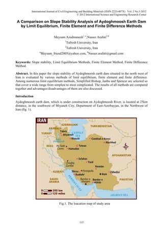
Aydoghmoosh earth dam, which is under construction on Aydoghmoosh River, is located at 25km
distance, in the southwest of Miyaneh City, Department of East-Azerbayjan, in the Northwest of
Iran (fig. 1).
Fig.1. The loacation map of study area
- 2. International Journal of Civil Engineering and Building Materials (ISSN 2223-487X) Vol. 2 No.3 2012
© 2012 International Science and Engineering Research Center
116
In this paper the Slope stability of this dam is evaluated by various methods of limit equilibrium,
finite element and finite difference.
Geotechnical parameters of Aydoghmoosh Earth Dam[5]
The height of the dam is about 75m and its length of crest is about 350m.
It is an earth dam with an inclined core made of impervious clay. The cross-section of this dam is
shown in fig.2.
Fig.2. Cross section of Aydoghmoosh Earth Dam
According to the results of the geotechnical study and the tests accomplished in the site and in
laboratory, the mechanical characteristics of materials are evaluated. These results are resumed in
table 1.
Table 1. Mechanical characteristics of dam materials
- 3. International Journal of Civil Engineering and Building Materials (ISSN 2223-487X) Vol. 2 No.3 2012
© 2012 International Science and Engineering Research Center
117
Slope stability analysis of Aydoghmoosh earth dam by Limit Equilibrium Method (LEM)
[1,3,9]
Limit Equilibrium Analysis was performed by the programs Slope version 12.01 and Slide version
5.
Slope is an analytical tool for the design of slopes and reinforced soils. The software supports
Fellenius, Janbu and simplified Bishop method.
The cross section of Aydoghmoosh earth dam as prepared by the programs Slope is shown in fig.3.
The safety factor and sliding surface of an analysis is also shown in this figure.
Fellenius method is not applicable to submereged slopes. Two analysis were performed with the
program Slope, one with Simplified Bishop Method and a second with the Janbu method.
Safety factors of 1.494 and 1.270 were obtained with Simplified Bishop and Janbu methods
respectively.
- 4. International Journal of Civil Engineering and Building Materials (ISSN 2223-487X) Vol. 2 No.3 2012
© 2012 International Science and Engineering Research Center
118
Fig.3. Cross section of Aydoghmoosh earth dam by the programs Slope
Slide is a 2 dimensional stability analysis program that considers geomechanical- geometrics of
unstable area and the amount of underground water.
The cross section of Aydoghmoosh earth dam as prepared by the program Slide is also shown in
fig.4. The safety factor and sliding surface of an analysis is shown in this figure too.
Two analysis were performed with the program Slide, one with Simplified Bishop Method and a
second with the Spencer method.
Safety factors of 1.492 and 1.490 were obtained with Simplified Bishop and Spencer methods
respectively that are in full match with the results of the program Slope.
Fig.4. Cross section of Aydoghmoosh earth dam by the programs Slide
Slope stability analysis of Aydoghmoosh earth dam by Finite Elements Method (FEM) )[4,6]
- 5. International Journal of Civil Engineering and Building Materials (ISSN 2223-487X) Vol. 2 No.3 2012
© 2012 International Science and Engineering Research Center
119
Finite Element Analysis was performed by the program Plaxis. In this program, the parameters C
and tgΦ are decreased gradually and the safety factor is calculated by the eq.1.
Where C and tgΦ are the real parameters as mentioned in fig.2, and Cr and tgΦr are decreased
parameters.
The cross section of Aydoghmoosh earth dam as prepared by the programs Plaxis is also shown in
fig.5.The overall displacement of the cross section and critical failure surface are presented in fig.6
and fig.7.
A safety factors of 1.596 was obtained with this program.
Fig.5. Cross section and mesh generation of Aydoghmoosh earth dam by the program Plaxis
Fig.6. Overall displacement of Aydoghmoosh earth dam by the program Plaxis
- 6. International Journal of Civil Engineering and Building Materials (ISSN 2223-487X) Vol. 2 No.3 2012
© 2012 International Science and Engineering Research Center
120
Fig.7. Critical failure surface of Aydoghmoosh earth dam by the program Plaxis
Slope stability analysis of Aydoghmoosh earth dam by Finite Difference Method (FDM) [7,8]
Finite Difference Analysis was performed by the program Flac/Slope. Flac/Slope is a small version
of Flac.
The cross section of Aydoghmoosh earth dam as prepared by the programs Flac/Slope is shown in
fig.8 as well. Also the mesh generation and final safety factor of Aydoghmoosh earth dam by the
program Flac/Slope are presented in fig.9.
A safety factors of 1.79 was obtained with this program.
Fig.8. Cross section of Aydoghmoosh earth dam by the programs Flac/Slope
Fig.9. Mesh generation and final safety factor of Aydoghmoosh earth dam by the program
Flac/Slope
Comparison of the results of slope stability analysis by different methods
- 7. International Journal of Civil Engineering and Building Materials (ISSN 2223-487X) Vol. 2 No.3 2012
© 2012 International Science and Engineering Research Center
121
The safety factor, obtained by various methods of LEM, FEM and FDM are presented together in
fig 10.
Fig.10. Comparison of the results of slope stability analysis methods
Safety factor obtained by Simplified Bishop Method and FEM are 1.494 and 1.596 respectly. The
results of LEM and FEM are almost equal. Wright (1969) and Wright, Kulhway, Duncan (1973)
have also riched to similar results.
Comparing the results of FEM and FDM, the safety factor obtained by FDM is 1.79 and almost 12
percent higher than FEM method.
The major differences between two program is that in FEM the parameter of elasticity modulus
interfers in calculation of safety factor but in FDM this parameter wouldn't considered.
Effect of elasticity modulus on the stability safety factor
To study the effect of soil elasticity modulus on the stability safety factor, a series of analysis were
performed by the program plaxis in which all the parameters exept elasticity modulus were kept
constant as mentioned in table 1. Only the elasticity modulus of all layers of the dam materials were
changed. In a first analysis the elasticity modulus were divided by two, and in other analysis they
were multipled by two, five and ten. The obtained stability safety factor of these analysis and the
rate of elasticity modulus change toward the initial state are presented in table 2. and fig.11. As
seen, the safety factor increases gradually with the elasticity modulus. This increase is more
important in the first three cases in this analysis, where the values of elasticity modulus is expected
to be more real. This means that an appropriate determination of elasticity modulus of soil has a
significant role on determination of stability safety factor.
Table 2. Sensivity analysis of elastic modulus on stability safety factor
Rate of Modulus of Elasticity
change toward the initial state
Safety Factor
Half of the initial state 1.454
Initial state 1.596
Twice of the initial state 1.674
5 times of the initial state 1.881
- 8. International Journal of Civil Engineering and Building Materials (ISSN 2223-487X) Vol. 2 No.3 2012
© 2012 International Science and Engineering Research Center
122
10 times of the initial state 2.133
15 times of the initial state 2.448
20 times of the initial state 2.984
Fig. 11. Sensivity analysis of elastic modulus on stability safety factor
Summary
1- Although the Simplified Bishop Method, is simple, it is already an exact method, and the
equation solving is done by trial and error method, but replies very quick and in all cases the
equation is convergent. Simplified Bishop Method is considered as a simple and almost exact
method in short dam designing.
2- Janbu Method is one of the most exact methods among the LEM. It is also solved by trial and
error method and in most cases it is convergent and leads to the answer.
3- FEM is an exact method that relates the stresses and strains where both elastic and plastic
characteristics of the earth are mentioned.
4- The results of LEM and FEM are almost equal. Weright (1969) and Wright, Kulhway, Duncan
(1973) have also riched to the same results.
5- The safety factor obtained by FDM is almost 12 percent higher than FEM method. The major
differences between two program is that in FEM, the program considers the elasticity modulus in
calculations. Increasing the soil elasticity modulus conclude increasing of safety factor.
6- To study the effect of soil elasticity modulus on the stability safety factor, a series of analysis
were performed by the FEM program in which all the parameters exept elasticity modulus were
kept constant. As seen, the safety factor increases gradually with the elasticity modulus. This means
that an appropriate determination of elasticity modulus of soil has a significant role on
determination of stability safety factor.
References
[1] Cheng, Y.M., &C.K.Lau,(2008) Slope stability analysis and stabilization-New methods and
insight
- 9. International Journal of Civil Engineering and Building Materials (ISSN 2223-487X) Vol. 2 No.3 2012
© 2012 International Science and Engineering Research Center
123
[2] Zulfu Gurocak,2007 " Rock slope stability and excavatability assessment of rocks at the
Kapikaya dam site, Turkey"., Available online at www.sciencedirect.com
[3]D.L.Borin,2005,"Slope Stability Analysis and Reinforced Soil Design Program(SLOPE)",
Distributed by Geosolve.
[4] Brinkgreve R.B.J., editor. 2002. PLAXIS 2D–Version 8, www.plaxis.nl, A.A. Balkema
Publishers
[5] Band-Ab consultant Engineer,." Geotechnical report of Aydoghmoosh earth dam", 1992
[6]Zienkiewich, O. C., (1971), "The Finite Element Method in Engineering Science", McGraw-Hill
Book Co., New York.
[7] Desai,c& Christian, J. (1977). Numerical Methods in Geotechnical Engineering, McGraw Hill.
[8] Itasca Consulting Group,Inc.(2002)"Flac Slope 4."Minneapolis,Minnesota USA
[9] Rocscience, Slide version 5.0, (2000).User's manual.
[10] Wright, S.G., Kulhany, F.H., and Duncan, J M., "Accuracy of Equilibrium Slope Stability
Analysis."Proc. ASCE, Vol. 99, No. SM10, October, 1973.
[11] Wright, S.G., "A Study of Slope Stability and the Undrained Strength of Clay Shales."Ph.D.
Thesis, University of California, Berkeley, 1969.
![International Journal of Civil Engineering and Building Materials (ISSN 2223-487X) Vol. 2 No.3 2012
© 2012 International Science and Engineering Research Center
116
In this paper the Slope stability of this dam is evaluated by various methods of limit equilibrium,
finite element and finite difference.
Geotechnical parameters of Aydoghmoosh Earth Dam[5]
The height of the dam is about 75m and its length of crest is about 350m.
It is an earth dam with an inclined core made of impervious clay. The cross-section of this dam is
shown in fig.2.
Fig.2. Cross section of Aydoghmoosh Earth Dam
According to the results of the geotechnical study and the tests accomplished in the site and in
laboratory, the mechanical characteristics of materials are evaluated. These results are resumed in
table 1.
Table 1. Mechanical characteristics of dam materials](data:image/gif;base64,R0lGODlhAQABAIAAAAAAAP///yH5BAEAAAAALAAAAAABAAEAAAIBRAA7)