Construction and Design Features of ICF Coaching Bogies
•Download as PPT, PDF•
34 likes•15,651 views

Presentation on fabrication and function of ICF bogies used in worldwide Locomotive...:):)

Recommended
More Related Content
What's hot
What's hot (20)
Similar to Construction and Design Features of ICF Coaching Bogies
Similar to Construction and Design Features of ICF Coaching Bogies (20)
More from Deepak Solanki
More from Deepak Solanki (14)
Recently uploaded
Recently uploaded (20)
Construction and Design Features of ICF Coaching Bogies
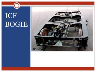
- 1. ICF BOGIE
- 2. Construction of coaching stock Shell i.e. the skeleton part. Furnishing i.e. the provisions of amenities. Bogie (Trolley) with the running gear.
- 3. Safety Concern of Coaches Safety, speed as well as comfort mainly depend on the bogie on which the coach is placed.
- 4. Bogie – What ? It is an independent unit used under a long vehicle, usually mounted on two pairs of wheels (except some special purpose stocks). Each bogie is provided with a bolster for engagement with its male counterpart provided underneath the vehicle under frame. The bogie trucks can swivel and adjust it’s position with case and without restraining the vehicle body while negotiating a curved track.
- 5. Bogie – Why ? Limitation of maximum rigid wheel base of a vehicle. Limitation of maximum axle load prescribed for track. Full utilisation of track loading density.
- 6. Factors for Designing A Bogie Sturdy construction to withstand vertical, longitudinal and lateral shocks. Suitable suspension gear. Satisfactory damping devices. Sturdy running gears to give trouble free service. Easy negotiability on curved track without restraining body structure
- 7. Versions of Coaching Bogie IRS Bogie SCHLIEREN Bogie (ICF Laminated Bogie) MAN-HAL Bogie (BEML Bogie) ICF All Coiled Bogie IR-20 Bogie Fiat Bogie (Similar to IR-20 Bogie)
- 8. IRS Bogie
- 9. IRS Bogie Developed / Built: British Make Introduction on IR in 1930–31 Current status: Productions abolished and use discontinued on Mail/express service.
- 10. SCHLIEREN Bogie (ICF Laminated Bogie)
- 11. SCHLIEREN Bogie (ICF Laminated Bogie) Developed / Built: M/S Swiss car and elevator manufacturing corporation Ltd, Schlieren, Zurich. Introduction on IR in 1951. Current status: Productions abolished and use discontinued on Mail/express service.
- 12. MAN-HAL Bogie (BEML Bogie)
- 13. MAN-HAL Bogie (BEML Bogie) Developed/Built: M/S HAL Banglore in collaboration with M/S MAN Nurnberg (West Germany) Introduction on IR in 1958-59 Current status: Productions abolished and use discontinued on Mail/express service.
- 14. ICF All Coiled Bogie
- 15. ICF All Coiled Bogie Developed/Built: ICF & RCF Introduction on IR in 1965 Current status: Productions continue by ICF & RCF.
- 16. IR-20 Bogie Developed/Built by: RCF. Introduction on IR in 1998. Current status: Used in few coaches and production abolished due to introduction of FIAT bogie.
- 17. Fiat Bogie
- 18. Fiat Bogie Similar to IR-20 Bogie. Developed/Built: FIAT Switzerland. Introduction on IR in 2001 (24 coaches imported from Switzerland). Current status: Productions continue in RCF.
- 19. Basic parameters of ICF Bogie
- 20. Main Units of ICF Bogie Bogie bolster with side bearers & centre pivot Bogie frame Wheel and axle Body–bogie bolster joint Bogie bolster–bogie frame joint Bogie frame–axle joint Secondary suspension (between bogie bolster & bogie frame) Primary suspension (between bogie frame & axle) Bearing arrangement in axle box Brake system
- 21. Bolster, side bearers & centre pivot The weight is taken at the side bearer on the top of the bolster. No weight comes at the centre pivot. The pivot acts only as a point of rotation and guidance of the bogie.
- 22. Side Bearers
- 23. Side Bearers Consists of a machined steel wearing plate immersed in an oil bath Floating bronze-wearing piece with a spherical top surface kept in it The coach body rests on the top spherical surface of these bronze-wearing pieces through the corresponding attachments on the bottom of the bodybolster.
- 24. Centre Pivot
- 25. Bogie Frame
- 26. Bogie Frame All welded light weight construction. The two main sole plates of ‘I’ section are connected at other ends by headstocks and at the centre by the transoms. Total 4 nos. Longitudinal beams (2 at either side) are connected between headstock and transom.
- 27. Wheel and Axle
- 28. Body–Bogie Joint The centre pivot pin joins the body with the bogie and transmits the tractive and braking forces on the bogies. It does not transmit any vertical load. It is equipped with rubber silent block bushes which tend to centralise the bogies with respect to the body and, to some extent, control and damp the angular oscillations of the bogies.
- 29. Bogie Bolster–Bogie Frame Joint Anchor links One anchor link is provided on each side of the bolster diagonally across which connects the bolster with bogie frame (Total nos. 2). Can swivel universally to permit the bolster to rise and fall and sway side wards. Fitted with silent block bushes. It holds the floating bogie bolster in position longitudinally. Designed to take the tractive and braking forces.
- 30. Bogie Frame–Axle Joint • Axle Guide Arrangement Description Axle box guides are of cylindrical type welded to the bottom flanges of the bogie side frame with close dimensional accuracy. These guides together with lower spring seats located over the axle box wings, house the axle box springs and also serve as shock absorbers.
- 31. Bogie Frame–Axle Joint Axle Guide Arrangement Function A rigid axle guide arrangement, which alone guides the axle longitudinally as well as transversely by eliminating any relative movement between axles & bogie frame. Designed to transmit tractive & braking force between bogie frame & axle. It acts as a single acting hydraulic shock absorber for primary suspension.
- 32. Primary & Secondary Suspension
- 34. Limitations of ICF bogie Design Longitudinal and transverse flexibilities of the axle guidance cannot be optimised. independently as generally required for highspeed bogies. There are vertical space constraints to accommodate desirably softer secondary suspension springs. Headstocks increase the yaw inertia of the bogie.