Sachpazis: Two-way RC Slab Slab Analysis & Design (EN1992-1-1:2004) example
•
5 likes•1,410 views

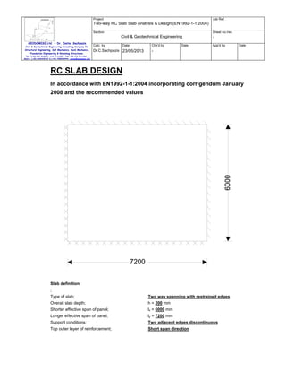
Two-way RC Slab Slab Analysis & Design, In accordance with EN1992-1-1:2004 incorporating corrigendum January 2008 and the recommended values.

Recommended
Recommended
More Related Content
What's hot
What's hot (20)
Similar to Sachpazis: Two-way RC Slab Slab Analysis & Design (EN1992-1-1:2004) example
Similar to Sachpazis: Two-way RC Slab Slab Analysis & Design (EN1992-1-1:2004) example (20)
More from Dr.Costas Sachpazis
More from Dr.Costas Sachpazis (20)
Recently uploaded
Recently uploaded (20)
Sachpazis: Two-way RC Slab Slab Analysis & Design (EN1992-1-1:2004) example
- 1. Project Job Ref. Two-way RC Slab Slab Analysis & Design (EN1992-1-1:2004) Section Sheet no./rev. Civil & Geotechnical Engineering GEODOMISI Ltd. - Dr. Costas Sachpazis Civil & Geotechnical Engineering Consulting Company for Structural Engineering, Soil Mechanics, Rock Mechanics, Foundation Engineering & Retaining Structures. Calc. by Chk'd by Date Dr.C.Sachpazis 23/05/2013 Date 1 App'd by Date - Tel.: (+30) 210 5238127, 210 5711263 - Fax.:+30 210 5711461 Mobile: (+30) 6936425722 & (+44) 7585939944, costas@sachpazis.info RC SLAB DESIGN In accordance with EN1992-1-1:2004 incorporating corrigendum January 2008 and the recommended values 7200 Slab definition ; Type of slab; Two way spanning with restrained edges Overall slab depth; h = 200 mm Shorter effective span of panel; lx = 6000 mm Longer effective span of panel; ly = 7200 mm Support conditions; Two adjacent edges discontinuous Top outer layer of reinforcement; Short span direction
- 2. Project Job Ref. Two-way RC Slab Slab Analysis & Design (EN1992-1-1:2004) Section Sheet no./rev. Civil & Geotechnical Engineering GEODOMISI Ltd. - Dr. Costas Sachpazis Civil & Geotechnical Engineering Consulting Company for Structural Engineering, Soil Mechanics, Rock Mechanics, Foundation Engineering & Retaining Structures. Calc. by Chk'd by Date Dr.C.Sachpazis 23/05/2013 1 Date App'd by Date - Tel.: (+30) 210 5238127, 210 5711263 - Fax.:+30 210 5711461 Mobile: (+30) 6936425722 & (+44) 7585939944, costas@sachpazis.info Bottom outer layer of reinforcement; Short span direction Loading Characteristic permanent action; Gk = 6.0 kN/m 2 Characteristic variable action; Qk = 5.0 kN/m 2 Partial factor for permanent action; γG = 1.35 Partial factor for variable action; γQ = 1.50 Quasi-permanent value of variable action; ψ2 = 0.30 Design ultimate load; q = γG × Gk + γQ × Qk = 15.6 kN/m Quasi-permanent load; qSLS = 1.0 × Gk + ψ2 × Qk = 7.5 kN/m 2 2 Concrete properties Concrete strength class; C25/30 Characteristic cylinder strength; fck = 25 N/mm Partial factor (Table 2.1N); γC = 1.50 2 Compressive strength factor (cl. 3.1.6); αcc = 1.00 Design compressive strength (cl. 3.1.6); fcd = 16.7 N/mm Mean axial tensile strength (Table 3.1); fctm = 0.30 N/mm × (fck / 1 N/mm ) Maximum aggregate size; dg = 20 mm 2 2 2 2/3 = 2.6 N/mm 2 Reinforcement properties Characteristic yield strength; fyk = 500 N/mm 2 Partial factor (Table 2.1N); γS = 1.15 Design yield strength (fig. 3.8); fyd = fyk / γS = 434.8 N/mm 2 Concrete cover to reinforcement Nominal cover to outer top reinforcement; cnom_t = 25 mm Nominal cover to outer bottom reinforcement; cnom_b = 20 mm Fire resistance period to top of slab; Rtop = 60 min Fire resistance period to bottom of slab; Rbtm = 60 min Axia distance to top reinft (Table 5.8); afi_t = 10 mm Axia distance to bottom reinft (Table 5.8); afi_b = 10 mm Min. top cover requirement with regard to bond; cmin,b_t = 12 mm Min. btm cover requirement with regard to bond; cmin,b_b = 10 mm Reinforcement fabrication; Subject to QA system Cover allowance for deviation; ∆cdev = 5 mm Min. required nominal cover to top reinft; cnom_t_min = 17.0 mm Min. required nominal cover to bottom reinft; cnom_b_min = 15.0 mm PASS - There is sufficient cover to the top reinforcement PASS - There is sufficient cover to the bottom reinforcement Reinforcement design at midspan in short span direction (cl.6.1) Bending moment coefficient; βsx_p = 0.0470 Design bending moment; Mx_p = βsx_p × q × lx = 26.4 kNm/m Reinforcement provided; 10 mm dia. bars at 200 mm centres 2
- 3. Project Job Ref. Two-way RC Slab Slab Analysis & Design (EN1992-1-1:2004) Section Sheet no./rev. Civil & Geotechnical Engineering GEODOMISI Ltd. - Dr. Costas Sachpazis Civil & Geotechnical Engineering Consulting Company for Structural Engineering, Soil Mechanics, Rock Mechanics, Foundation Engineering & Retaining Structures. Calc. by Chk'd by Date Dr.C.Sachpazis 23/05/2013 1 Date App'd by Date - Tel.: (+30) 210 5238127, 210 5711263 - Fax.:+30 210 5711461 Mobile: (+30) 6936425722 & (+44) 7585939944, costas@sachpazis.info 2 Area provided; Asx_p = 393 mm /m Effective depth to tension reinforcement; dx_p = h - cnom_b - φx_p / 2 = 175.0 mm K factor; K = Mx_p / (b × dx_p × fck) = 0.034 Redistribution ratio; δ = 1.0 K’ factor; K’ = 0.598 × δ - 0.18 × δ - 0.21 = 0.208 2 2 K < K' - Compression reinforcement is not required 0.5 Lever arm; z = min(0.95 × dx_p, dx_p/2 × (1 + (1 - 3.53×K) )) = 166.3 mm 2 Area of reinforcement required for bending; Asx_p_m = Mx_p / (fyd × z) = 365 mm /m Minimum area of reinforcement required; Asx_p_min = max(0.26 × (fctm/fyk) × b × dx_p, 2 0.0013×b×dx_p) = 233 mm /m 2 Asx_p_req = max(Asx_p_m, Asx_p_min) = 365 mm /m Area of reinforcement required; PASS - Area of reinforcement provided exceeds area required Check reinforcement spacing Reinforcement service stress; = 194.4 N/mm σsx_p = (fyk / γS) × min((Asx_p_m/Asx_p), 1.0) × qSLS / q 2 Maximum allowable spacing (Table 7.3N); Actual bar spacing; smax_x_p = 257 mm sx_p = 200 mm PASS - The reinforcement spacing is acceptable Reinforcement design at midspan in long span direction (cl.6.1) Bending moment coefficient; βsy_p = 0.0340 Design bending moment; My_p = βsy_p × q × lx = 19.1 kNm/m 2 Reinforcement provided; 10 mm dia. bars at 250 mm centres Area provided; Asy_p = 314 mm /m 2 Effective depth to tension reinforcement; dy_p = h - cnom_b - φx_p - φy_p / 2 = 165.0 mm K factor; K = My_p / (b × dy_p × fck) = 0.028 Redistribution ratio; δ = 1.0 K’ factor; K’ = 0.598 × δ - 0.18 × δ - 0.21 = 0.208 2 2 K < K' - Compression reinforcement is not required 0.5 Lever arm; z = min(0.95 × dy_p, dy_p/2 × (1 + (1 - 3.53×K) )) = 156.8 mm 2 Area of reinforcement required for bending; Asy_p_m = My_p / (fyd × z) = 280 mm /m Minimum area of reinforcement required; Asy_p_min = max(0.26 × (fctm/fyk) × b × dy_p, 2 0.0013×b×dy_p) = 220 mm /m 2 Area of reinforcement required; Asy_p_req = max(Asy_p_m, Asy_p_min) = 280 mm /m PASS - Area of reinforcement provided exceeds area required Check reinforcement spacing Reinforcement service stress; = 186.4 N/mm σsy_p = (fyk / γS) × min((Asy_p_m/Asy_p), 1.0) × qSLS / q 2 Maximum allowable spacing (Table 7.3N); smax_y_p = 267 mm
- 4. Project Job Ref. Two-way RC Slab Slab Analysis & Design (EN1992-1-1:2004) Section Sheet no./rev. Civil & Geotechnical Engineering GEODOMISI Ltd. - Dr. Costas Sachpazis Civil & Geotechnical Engineering Consulting Company for Structural Engineering, Soil Mechanics, Rock Mechanics, Foundation Engineering & Retaining Structures. Calc. by Chk'd by Date Dr.C.Sachpazis 23/05/2013 1 Date App'd by Date - Tel.: (+30) 210 5238127, 210 5711263 - Fax.:+30 210 5711461 Mobile: (+30) 6936425722 & (+44) 7585939944, costas@sachpazis.info Actual bar spacing; sy_p = 250 mm PASS - The reinforcement spacing is acceptable Reinforcement design at continuous support in short span direction (cl.6.1) Bending moment coefficient; βsx_n = 0.0630 Design bending moment; Mx_n = βsx_n × q × lx = 35.4 kNm/m Reinforcement provided; 12 mm dia. bars at 200 mm centres Area provided; Asx_n = 565 mm /m Effective depth to tension reinforcement; dx_n = h - cnom_t - φx_n / 2 = 169.0 mm K factor; K = Mx_n / (b × dx_n × fck) = 0.050 Redistribution ratio; δ = 1.0 K’ factor; K’ = 0.598 × δ - 0.18 × δ - 0.21 = 0.208 2 2 2 2 K < K' - Compression reinforcement is not required 0.5 Lever arm; z = min(0.95 × dx_n, dx_n/2 × (1 + (1 - 3.53×K) )) = 160.5 mm 2 Area of reinforcement required for bending; Asx_n_m = Mx_n / (fyd × z) = 507 mm /m Minimum area of reinforcement required; Asx_n_min = max(0.26 × (fctm/fyk) × b × dx_n, 2 0.0013×b×dx_n) = 225 mm /m 2 Area of reinforcement required; Asx_n_req = max(Asx_n_m, Asx_n_min) = 507 mm /m PASS - Area of reinforcement provided exceeds area required Check reinforcement spacing Reinforcement service stress; = 187.4 N/mm σsx_n = (fyk / γS) × min((Asx_n_m/Asx_n), 1.0) × qSLS / q 2 Maximum allowable spacing (Table 7.3N); Actual bar spacing; smax_x_n = 266 mm sx_n = 200 mm PASS - The reinforcement spacing is acceptable Reinforcement design at continuous support in long span direction (cl.6.1) Bending moment coefficient; βsy_n = 0.0450 Design bending moment; My_n = βsy_n × q × lx = 25.3 kNm/m 2 Reinforcement provided; 10 mm dia. bars at 200 mm centres Area provided; Asy_n = 393 mm /m 2 Effective depth to tension reinforcement; dy_n = h - cnom_t - φx_n - φy_n / 2 = 158.0 mm K factor; K = My_n / (b × dy_n × fck) = 0.040 Redistribution ratio; δ = 1.0 K’ factor; K’ = 0.598 × δ - 0.18 × δ - 0.21 = 0.208 2 2 K < K' - Compression reinforcement is not required 0.5 Lever arm; z = min(0.95 × dy_n, dy_n/2 × (1 + (1 - 3.53×K) )) = 150.1 mm 2 Area of reinforcement required for bending; Asy_n_m = My_n / (fyd × z) = 387 mm /m Minimum area of reinforcement required; Asy_n_min = max(0.26 × (fctm/fyk) × b × dy_n, 2 0.0013×b×dy_n) = 211 mm /m
- 5. Project Job Ref. Two-way RC Slab Slab Analysis & Design (EN1992-1-1:2004) Section Sheet no./rev. Civil & Geotechnical Engineering GEODOMISI Ltd. - Dr. Costas Sachpazis Civil & Geotechnical Engineering Consulting Company for Structural Engineering, Soil Mechanics, Rock Mechanics, Foundation Engineering & Retaining Structures. Calc. by Date Dr.C.Sachpazis 23/05/2013 Chk'd by 1 Date App'd by Date - Tel.: (+30) 210 5238127, 210 5711263 - Fax.:+30 210 5711461 Mobile: (+30) 6936425722 & (+44) 7585939944, costas@sachpazis.info 2 Area of reinforcement required; Asy_n_req = max(Asy_n_m, Asy_n_min) = 387 mm /m PASS - Area of reinforcement provided exceeds area required Check reinforcement spacing Reinforcement service stress; = 206.1 N/mm σsy_n = (fyk / γS) × min((Asy_n_m/Asy_n), 1.0) × qSLS / q 2 Maximum allowable spacing (Table 7.3N); smax_y_n = 242 mm Actual bar spacing; sy_n = 200 mm PASS - The reinforcement spacing is acceptable Shear capacity check at short span continuous support Shear force; Vx_n = q × lx / 2 + Mx_n / lx = 52.7 kN/m Effective depth factor (cl. 6.2.2); k = min(2.0, 1 + (200 mm / dx_n) ) = 2.000 Reinforcement ratio; ρl = min(0.02, Asx_n / (b × dx_n)) = 0.0033 Minimum shear resistance (Exp. 6.3N); VRd,c_min = 0.035 N/mm × k 0.5 2 1.5 2 0.5 × (fck / 1 N/mm ) × b × dx_n VRd,c_min = 83.7 kN/m Shear resistance (Exp. 6.2a); 2 N/mm )) 0.333 2 VRd,c_x_n = max(VRd,c_min, (0.18 N/mm / γC) × k × (100 × ρl × (fck / 1 × b × dx_n) VRd,c_x_n = 83.7 kN/m PASS - Shear capacity is adequate Shear capacity check at long span continuous support Shear force; Vy_n = q × lx / 2 + My_n / ly = 50.3 kN/m Effective depth factor (cl. 6.2.2); k = min(2.0, 1 + (200 mm / dy_n) ) = 2.000 Reinforcement ratio; ρl = min(0.02, Asy_n / (b × dy_n)) = 0.0025 Minimum shear resistance (Exp. 6.3N); VRd,c_min = 0.035 N/mm × k 0.5 2 1.5 2 0.5 × (fck / 1 N/mm ) × b × dy_n VRd,c_min = 78.2 kN/m Shear resistance (Exp. 6.2a); 2 N/mm )) 0.333 2 VRd,c_y_n = max(VRd,c_min, (0.18 N/mm / γC) × k × (100 × ρl × (fck / 1 × b × dy_n) VRd,c_y_n = 78.2 kN/m PASS - Shear capacity is adequate Shear capacity check at short span discontinuous support Shear force; Vx_d = q × lx / 2 = ;46.8; kN/m; Reinforcement provided; 8 mm dia. bars at 200 mm centres Area provided; Asx_d = 251 mm /m Effective depth; dx_d = h - cnom_b - φx_d / 2 = ;176.0; mm Effective depth factor; k = min(2.0, 1 + (200 mm / dx_d) ) = 2.000 2 0.5 Reinforcement ratio; ρl = min(0.02, Asx_d / (b × dx_d)) = 0.0014 Minimum shear resistance; VRd,c_min = 0.035 N/mm × k 2 b × dx_d VRd,c_min = 87.1 kN/m 1.5 2 0.5 × (fck / 1 N/mm ) ×
- 6. Project Job Ref. Two-way RC Slab Slab Analysis & Design (EN1992-1-1:2004) Section Sheet no./rev. Civil & Geotechnical Engineering GEODOMISI Ltd. - Dr. Costas Sachpazis Civil & Geotechnical Engineering Consulting Company for Structural Engineering, Soil Mechanics, Rock Mechanics, Foundation Engineering & Retaining Structures. Calc. by Chk'd by Date Dr.C.Sachpazis 23/05/2013 1 Date App'd by Date - Tel.: (+30) 210 5238127, 210 5711263 - Fax.:+30 210 5711461 Mobile: (+30) 6936425722 & (+44) 7585939944, costas@sachpazis.info 2 Shear resistance; 2 N/mm )) 0.333 VRd,c_x_d = max(VRd,c_min, 0.18 N/mm / γC × k × (100 × ρl × (fck/1 × b × dx_d) VRd,c_x_d = 87.1 kN/m PASS - Shear capacity is adequate (0.537) Shear capacity check at long span discontinuous support Shear force; Vy_d = q × lx / 2 = ;46.8; kN/m; Reinforcement provided; 8 mm dia. bars at 250 mm centres Area provided; Asy_d = 201 mm /m 2 Effective depth; dy_d = h - cnom_b - φx_p - φy_d / 2 = ;166.0; mm Effective depth factor; k = min(2.0, 1 + (200 mm / dy_d) ) = 2.000 Reinforcement ratio; ρl = min(0.02, Asy_d / (b × dy_d)) = 0.0012 Minimum shear resistance; VRd,c_min = 0.035 N/mm × k 0.5 2 1.5 2 0.5 × (fck / 1 N/mm ) × b × dy_d VRd,c_min = 82.2 kN/m 2 Shear resistance; 2 N/mm )) 0.333 VRd,c_y_d = max(VRd,c_min, 0.18 N/mm / γC × k × (100 × ρl × (fck/1 × b × dy_d) VRd,c_y_d = 82.2 kN/m PASS - Shear capacity is adequate (0.570) Basic span-to-depth deflection ratio check (cl. 7.4.2) 2 0.5 Reference reinforcement ratio; ρ0 = (fck / 1 N/mm ) / 1000 = 0.0050 Required tension reinforcement ratio; ρ = max(0.0035, Asx_p_req / (b × dx_p)) = 0.0035 Required compression reinforcement ratio; ρ’ = Ascx_p_req / (b × dx_p) = 0.0000 Stuctural system factor (Table 7.4N); Kδ = 1.3 2 0.5 Basic limit span-to-depth ratio; ratiolim_x_bas = Kδ × [11 +1.5×(fck/1 N/mm ) ×ρ0/ρ + 3.2×(fck/1 2 0.5 1.5 N/mm ) ×(ρ0/ρ -1) ] (Exp. 7.16); ratiolim_x_bas = 34.06 Modified limit span-to-eff. depth ratio; ratiolim_x = min(1.5, (500 N/mm /fyk)×( Asx_p/Asx_p_m)) 2 × ratiolim_x_bas = 36.63 Actual span-to-eff. depth ratio; ratioact_x = lx / dx_p = 34.29 PASS - Actual span-to-effective depth ratio is acceptable Reinforcement summary Midspan in short span direction; 10 mm dia. bars at 200 mm centres B1 Midspan in long span direction; 10 mm dia. bars at 250 mm centres B2 Continuous support in short span direction; 12 mm dia. bars at 200 mm centres T1 Continuous support in long span direction; 10 mm dia. bars at 200 mm centres T2 Discontinuous support in short span direction; 8 mm dia. bars at 200 mm centres B1 Discontinuous support in long span direction; 8 mm dia. bars at 250 mm centres B2 Reinforcement sketch The following sketch is indicative only. Note that additional reinforcement may be required in accordance with clauses 9.2.1.2, 9.2.1.4 and 9.2.1.5 of EN 1992-1-1:2004 to meet detailing rules.
- 7. Project Job Ref. Two-way RC Slab Slab Analysis & Design (EN1992-1-1:2004) Section Sheet no./rev. Civil & Geotechnical Engineering GEODOMISI Ltd. - Dr. Costas Sachpazis Civil & Geotechnical Engineering Consulting Company for Structural Engineering, Soil Mechanics, Rock Mechanics, Foundation Engineering & Retaining Structures. Calc. by Date Dr.C.Sachpazis 23/05/2013 Chk'd by - 8mm bars @ 250 ctrs B2 10mm bars @ 250 ctrs B2 10mm bars @ 200 ctrs T2 Tel.: (+30) 210 5238127, 210 5711263 - Fax.:+30 210 5711461 Mobile: (+30) 6936425722 & (+44) 7585939944, costas@sachpazis.info Date 1 App'd by Date