SlideShare a Scribd company logo
1 of 23
Download to read offline
Job Ref.

Flat Slab Analysis & Design, In accordance with
BS8110:PART 1:1997
Project:

Section

Sheet no./rev. 1

Civil & Geotechnical Engineering

GEODOMISI Ltd. - Dr. Costas Sachpazis
Civil & Geotechnical Engineering Consulting Company for
Structural Engineering, Soil Mechanics, Rock Mechanics,
Foundation Engineering & Retaining Structures.

Date

Calc. by

Dr. C. Sachpazis

Tel.: (+30) 210 5238127, 210 5711263 - Fax.:+30 210 5711461 Mobile: (+30) 6936425722 & (+44) 7585939944, costas@sachpazis.info

Chk'd by
Date

18/01/2014

App'd by

Date

FLAT SLAB DESIGN TO BS8110:PART 1:1997
Slab geometry
Span of slab in x-direction;

Spanx = 7200 mm

Span of slab in y-direction;

Spany = 7200 mm

Column dimension in x-direction;

lx = 400 mm

Column dimension in y-direction;

ly = 400 mm

External column dimension in x-direction;

lx1 = 250 mm

External column dimension in y-direction;

ly1 = 250 mm

Edge dimension in x-direction;

ex = lx1 / 2 = 125 mm

Edge dimension in y-direction;

ey = ly1 / 2 = 125 mm

Effective span of internal bay in x direction;

Lx = Spanx – lx = 6800 mm

Effective span of internal bay in y direction;

Ly = Spany – ly = 6800 mm

Effective span of end bay in x direction;

Lx1 = Spanx – lx / 2 = 7000 mm

Effective span of end bay in y direction;

Ly1 = Spany – ly / 2 = 7000 mm

ex

B

C

Span x

Span x

lx

ey
1

A

lx

l y1

Sp
an

y

lx1
ly

Sp
an

y

2

ly

3

h

Slab details
Depth of slab;

h = 250 mm
1
Job Ref.

Flat Slab Analysis & Design, In accordance with
BS8110:PART 1:1997
Project:

Section
Civil & Geotechnical Engineering Consulting Company for
Structural Engineering, Soil Mechanics, Rock Mechanics,
Foundation Engineering & Retaining Structures.

Sheet no./rev. 1

Civil & Geotechnical Engineering

GEODOMISI Ltd. - Dr. Costas Sachpazis

Calc. by

Tel.: (+30) 210 5238127, 210 5711263 - Fax.:+30 210 5711461 Mobile: (+30) 6936425722 & (+44) 7585939944, costas@sachpazis.info

Dr. C. Sachpazis

Date

Chk'd by
Date

18/01/2014

App'd by

Date

2

Characteristic strength of concrete;

fcu = 35 N/mm

Characteristic strength of reinforcement;

fy = 500 N/mm

Characteristic strength of shear reinforcement;

fyv = 500 N/mm

Material safety factor;

γm = 1.15

2
2

Cover to bottom reinforcement;

c = 20 mm

Cover to top reinforcement;

c’ = 20 mm

Loading details
2

Characteristic dead load;

Gk = 7.000 kN/m

Characteristic imposed load;

Qk = 5.000 kN/m

2

Dead load factor;

γG = 1.4

Imposed load factor;

γQ = 1.6

Total ultimate load;

Nult = (Gk × γG) + (Qk × γQ) = 17.800 kN/m

Moment redistribution ratio;

βb = 1.0

Ratio of support moments to span moments;

i = 1.0

2

DESIGN SLAB IN THE X-DIRECTION
SAGGING MOMENTS
End bay A-B
Effective span;

L = 7000 mm

Depth of reinforcement;

d = 200 mm

Midspan moment;

m = (Nult × L ) / (2 × (1 + √(1 + i)) ) = 74.823 kNm/m

Support moment;

m’ = i × m = 74.823 kNm/m

2

2

Design reinforcement
Lever arm;

2

K’ = 0.402 × (βb – 0.4) – 0.18 × (βb – 0.4) = 0.176
2

K = m / (d × fcu) = 0.053
Compression reinforcement is not required
z = min((0.5 + √(0.25 – (K / 0.9))), 0.95) × d = 187.3 mm
Area of reinforcement designed;

2

As_des = m / (z × fy / γm) = 919 mm /m
2

Minimum area of reinforcement required;

As_min = 0.0013 × h = 325 mm /m

Area of reinforcement required;

As_req = max(As_des, As_min) = 919 mm /m

2

Provide 20 dia bars @ 150 centres
Area of reinforcement provided;

2

2

As_prov = π × D / (4 × s) = 2094 mm /m
PASS - Span reinforcement is OK

Check deflection
Design service stress;

fs = 2 × fy × As_req / (3 × As_prov × βb) = 146 N/mm
2

2

2
2

Modification factor;

k1 = min(0.55+(477N/mm -fs)/(120×(0.9N/mm +(m/d ))),2) = 1.545

Allowable span to depth ratio;

0.9 × 26 × k1 = 36.151

Actual span to depth ratio;

L / d = 35.000
2
Job Ref.

Flat Slab Analysis & Design, In accordance with
BS8110:PART 1:1997
Project:

Section
Civil & Geotechnical Engineering Consulting Company for
Structural Engineering, Soil Mechanics, Rock Mechanics,
Foundation Engineering & Retaining Structures.

Sheet no./rev. 1

Civil & Geotechnical Engineering

GEODOMISI Ltd. - Dr. Costas Sachpazis

Calc. by

Tel.: (+30) 210 5238127, 210 5711263 - Fax.:+30 210 5711461 Mobile: (+30) 6936425722 & (+44) 7585939944, costas@sachpazis.info

Dr. C. Sachpazis

Date

Chk'd by
Date

18/01/2014

App'd by

Date

PASS - Span to depth ratio is OK
Internal bay B-C
Effective span;

L = 6800 mm

Depth of reinforcement;

d = 202 mm

Midspan moment;

m = (Nult × L ) / (2 × (√(1 + i) + √(1 + i)) ) = 51.442 kNm/m

Support moment;

m’ = i × m = 51.442 kNm/m

2

2

Design reinforcement
Lever arm;

2

K’ = 0.402 × (βb – 0.4) – 0.18 × (βb – 0.4) = 0.176
2

K = m / (d × fcu) = 0.036
Compression reinforcement is not required
z = min((0.5 + √(0.25 – (K / 0.9))), 0.95) × d = 191.9 mm
2

Area of reinforcement designed;

As_des = m / (z × fy / γm) = 617 mm /m

Minimum area of reinforcement required;

As_min = 0.0013 × h = 325 mm /m

Area of reinforcement required;

As_req = max(As_des, As_min) = 617 mm /m

2

2

Provide 16 dia bars @ 200 centres
Area of reinforcement provided;

2

2

As_prov = π × D / (4 × s) = 1005 mm /m
PASS - Span reinforcement is OK

Check deflection
2

Design service stress;

fs = 2 × fy × As_req / (3 × As_prov × βb) = 204 N/mm

Modification factor;

k1 = min(0.55+(477N/mm -fs)/(120×(0.9N/mm +(m/d ))),2) = 1.601

Allowable span to depth ratio;

0.9 × 26 × k1 = 37.469

Actual span to depth ratio;

L / d = 33.663

2

2

2

PASS - Span to depth ratio is OK
HOGGING MOMENTS – INTERNAL STRIP
Penultimate column B3
Consider the reinforcement concentrated in half width strip over the support
Depth of reinforcement;
d’ = 200 mm
Support moment;

m’ = 2 × i × m = 149.646 kNm/m

Lever arm;

K’ = 0.402 × (βb – 0.4) – 0.18 × (βb – 0.4) = 0.176

2

2

K = m’ / (d’ × fcu) = 0.107
Compression reinforcement is not required
z = min((0.5 + √(0.25 – (K / 0.9))), 0.95) × d’ = 172.5 mm
Area of reinforcement required;

2

As_des = m’ / (z × fy / γm) = 1996 mm /m
2

Minimum area of reinforcement required;

As_min = 0.0013 × h = 325 mm /m

Area of reinforcement required;

As_req = max(As_des, As_min) = 1996 mm /m

2

Provide 20 dia bars @ 150 centres
Area of reinforcement provided;

2

2

As_prov = π × D / (4 × s) = 2094 mm /m
PASS - Support reinforcement is OK
3
Job Ref.

Flat Slab Analysis & Design, In accordance with
BS8110:PART 1:1997
Project:

Section
Civil & Geotechnical Engineering Consulting Company for
Structural Engineering, Soil Mechanics, Rock Mechanics,
Foundation Engineering & Retaining Structures.

Sheet no./rev. 1

Civil & Geotechnical Engineering

GEODOMISI Ltd. - Dr. Costas Sachpazis

Calc. by

Tel.: (+30) 210 5238127, 210 5711263 - Fax.:+30 210 5711461 Mobile: (+30) 6936425722 & (+44) 7585939944, costas@sachpazis.info

Dr. C. Sachpazis

Date

Chk'd by
Date

18/01/2014

App'd by

Date

Internal column C3
Consider the reinforcement concentrated in half width strip over the support
Depth of reinforcement;
d’ = 200 mm
Support moment;

m’ = 2 × i × m = 102.884 kNm/m

Lever arm;

K’ = 0.402 × (βb – 0.4) – 0.18 × (βb – 0.4) = 0.176

2

2

K = m’ / (d’ × fcu) = 0.073
Compression reinforcement is not required
z = min((0.5 + √(0.25 – (K / 0.9))), 0.95) × d’ = 182.1 mm
2

Area of reinforcement required;

As_des = m’ / (z × fy / γm) = 1300 mm /m

Minimum area of reinforcement required;

As_min = 0.0013 × h = 325 mm /m

Area of reinforcement required;

As_req = max(As_des, As_min) = 1300 mm /m

2

2

Provide 20 dia bars @ 200 centres
Area of reinforcement provided;

2

2

As_prov = π × D / (4 × s) = 1571 mm /m
PASS - Support reinforcement is OK

HOGGING MOMENTS – EXTERNAL STRIP
Penultimate column B1, B2
Consider one and a half bays of negative moment being resisted over the edge and penultimate column
Width of span;

B = 7200 mm

Edge distance;

e = 125 mm

Depth of reinforcement;

d’ = 200 mm

Support moment;

m’ = m × i ×(e + B + B / 2) / ((0.5 × B) + (0.2 × B) + e) = 158.265

kNm/m
Lever arm;

2

K’ = 0.402 × (βb – 0.4) – 0.18 × (βb – 0.4) = 0.176
2

K = m’ / (d’ × fcu) = 0.113
Compression reinforcement is not required
z = min((0.5 + √(0.25 – (K / 0.9))), 0.95) × d’ = 170.5 mm
Area of reinforcement required;

2

As_des = m’ / (z × fy / γm) = 2134 mm /m
2

Minimum area of reinforcement required;

As_min = 0.0013 × h = 325 mm /m

Area of reinforcement required;

As_req = max(As_des, As_min) = 2134 mm /m

2

Provide 20 dia bars @ 125 centres
Area of reinforcement provided;

2

2

As_prov = π × D / (4 × s) = 2513 mm /m
PASS - Support reinforcement is OK

Internal column C1, C2
Consider one and a half bays of negative moment being resisted over the edge and penultimate column
Width of span;

B = 7200 mm

Edge distance;

e = 125 mm

Depth of reinforcement;

d’ = 200 mm

Support moment;

m’ = m × i ×(e + B + B / 2) / ((0.5 × B) + (0.2 × B) + e) = 108.810

kNm/m
4
Job Ref.

Flat Slab Analysis & Design, In accordance with
BS8110:PART 1:1997
Project:

Section
Civil & Geotechnical Engineering Consulting Company for
Structural Engineering, Soil Mechanics, Rock Mechanics,
Foundation Engineering & Retaining Structures.
Tel.: (+30) 210 5238127, 210 5711263 - Fax.:+30 210 5711461 Mobile: (+30) 6936425722 & (+44) 7585939944, costas@sachpazis.info

Sheet no./rev. 1

Civil & Geotechnical Engineering

GEODOMISI Ltd. - Dr. Costas Sachpazis

Calc. by

Dr. C. Sachpazis

Lever arm;

Date

Chk'd by
Date

18/01/2014

App'd by

Date

2

K’ = 0.402 × (βb – 0.4) – 0.18 × (βb – 0.4) = 0.176
2

K = m’ / (d’ × fcu) = 0.078
Compression reinforcement is not required
z = min((0.5 + √(0.25 – (K / 0.9))), 0.95) × d’ = 180.9 mm
2

Area of reinforcement required;

As_des = m’ / (z × fy / γm) = 1383 mm /m

Minimum area of reinforcement required;

As_min = 0.0013 × h = 325 mm /m

Area of reinforcement required;

As_req = max(As_des, As_min) = 1383 mm /m

2

2

Provide 20 dia bars @ 200 centres
Area of reinforcement provided;

2

2

As_prov = π × D / (4 × s) = 1571 mm /m
PASS - Support reinforcement is OK

Corner column A1
Depth of reinforcement;

d’ = 206 mm

Total load on column;

S = ((Spanx / 2) + ex) × ((Spany / 2) + ey) × Nult = 247 kN

Area of column head;

A = lx × ly1 = 0.100 m

Support moment;

m’ = S × (1 – (Nult × A / S) ) / 2 = 99.639 kNm/m

Lever arm;

K’ = 0.402 × (βb – 0.4) – 0.18 × (βb – 0.4) = 0.176

2
1/3

2

2

K = m’ / (d’ × fcu) = 0.067
Compression reinforcement is not required
z = min((0.5 + √(0.25 – (K / 0.9))), 0.95) × d’ = 189.3 mm
2

Area of reinforcement required;

As_des = m’ / (z × fy / γm) = 1211 mm /m

Minimum area of reinforcement required;

As_min = 0.0013 × h = 325 mm /m

Area of reinforcement required;

As_req = max(As_des, As_min) = 1211 mm /m

2

2

Provide 16 dia bars @ 150 centres
Area of reinforcement provided;

2

2

As_prov = π × D / (4 × s) = 1340 mm /m
PASS - Support reinforcement is OK

Edge column A2, A3
Depth of reinforcement;

d’ = 202 mm

Total load on column;

S = Spanx × (Spany / 2 + ey) × Nult = 477 kN

Area of column head;

A = lx1 × ly = 0.100 m

Support moment;

m’ = S × (1 – (Nult × A / S) ) / 5.14 = 78.476 kNm/m

Lever arm;

K’ = 0.402 × (βb – 0.4) – 0.18 × (βb – 0.4) = 0.176

2
1/3

2

2

K = m’ / (d’ × fcu) = 0.055
Compression reinforcement is not required
z = min((0.5 + √(0.25 – (K / 0.9))), 0.95) × d’ = 188.8 mm
Area of reinforcement required;

2

As_des = m’ / (z × fy / γm) = 956 mm /m
2

Minimum area of reinforcement required;

As_min = 0.0013 × h = 325 mm /m

Area of reinforcement required;

As_req = max(As_des, As_min) = 956 mm /m

2

Provide 16 dia bars @ 175 centres
Area of reinforcement provided;

2

2

As_prov = π × D / (4 × s) = 1149 mm /m
5
Job Ref.

Flat Slab Analysis & Design, In accordance with
BS8110:PART 1:1997
Project:

Section
Civil & Geotechnical Engineering Consulting Company for
Structural Engineering, Soil Mechanics, Rock Mechanics,
Foundation Engineering & Retaining Structures.
Tel.: (+30) 210 5238127, 210 5711263 - Fax.:+30 210 5711461 Mobile: (+30) 6936425722 & (+44) 7585939944, costas@sachpazis.info

Sheet no./rev. 1

Civil & Geotechnical Engineering

GEODOMISI Ltd. - Dr. Costas Sachpazis

Calc. by

Dr. C. Sachpazis

Date

Chk'd by
Date

18/01/2014

App'd by

Date

PASS - Support reinforcement is OK
Between columns 1-2, 2-3
Around the perimeter between the column heads provide a minimum of 50% of the required end span bottom
reinforcement.
Area of reinforcement required;

2

As_req = Asx1 / 2 = 1047 mm /m

Provide 16 dia bars @ 150 centres - 'U' bars with 1600 mm long legs
Area of reinforcement provided;

2

2

As_prov = π × D / (4 × s) = 1340 mm /m
PASS - Edge reinforcement is OK

Distribution reinforcement
Provide 12 dia bars @ 300 centres
Area of reinforcement provided;

2

2

As_prov = π × D / (4 × s) = 377 mm /m

DESIGN SLAB IN THE Y-DIRECTION
SAGGING MOMENTS
End bay 1-2
Effective span;

L = 7000 mm

Depth of reinforcement;

d = 220 mm

Midspan moment;

m = (Nult × L ) / (2 × (1 + √(1 + i)) ) = 74.823 kNm/m

Support moment;

m’ = i × m = 74.823 kNm/m

2

2

Design reinforcement
Lever arm;

2

K’ = 0.402 × (βb – 0.4) – 0.18 × (βb – 0.4) = 0.176
2

K = m / (d × fcu) = 0.044
Compression reinforcement is not required
z = min((0.5 + √(0.25 – (K / 0.9))), 0.95) × d = 208.6 mm
2

Area of reinforcement designed;

As_des = m / (z × fy / γm) = 825 mm /m

Minimum area of reinforcement required;

As_min = 0.0013 × h = 325 mm /m

Area of reinforcement required;

As_req = max(As_des, As_min) = 825 mm /m

2

2

Provide 20 dia bars @ 200 centres
Area of reinforcement provided;

2

2

As_prov = π × D / (4 × s) = 1571 mm /m
PASS - Span reinforcement is OK

Check deflection
2

Design service stress;

fs = 2 × fy × As_req / (3 × As_prov × βb) = 175 N/mm

Modification factor;

k1 = min(0.55+(477N/mm -fs)/(120×(0.9N/mm +(m/d ))),2) = 1.579

Allowable span to depth ratio;

0.9 × 26 × k1 = 36.942

Actual span to depth ratio;

L / d = 31.818

2

2

2

PASS - Span to depth ratio is OK
Internal bay 2-3
Effective span;

L = 6800 mm
6
Job Ref.

Flat Slab Analysis & Design, In accordance with
BS8110:PART 1:1997
Project:

Section
Civil & Geotechnical Engineering Consulting Company for
Structural Engineering, Soil Mechanics, Rock Mechanics,
Foundation Engineering & Retaining Structures.

Sheet no./rev. 1

Civil & Geotechnical Engineering

GEODOMISI Ltd. - Dr. Costas Sachpazis

Calc. by

Tel.: (+30) 210 5238127, 210 5711263 - Fax.:+30 210 5711461 Mobile: (+30) 6936425722 & (+44) 7585939944, costas@sachpazis.info

Dr. C. Sachpazis

Date

Chk'd by
Date

18/01/2014

App'd by

Date

Depth of reinforcement;

d = 222 mm

Midspan moment;

m = (Nult × L ) / (2 × (√(1 + i) + √(1 + i)) ) = 51.442 kNm/m

Support moment;

m’ = i × m = 51.442 kNm/m

2

2

Design reinforcement
Lever arm;

2

K’ = 0.402 × (βb – 0.4) – 0.18 × (βb – 0.4) = 0.176
2

K = m / (d × fcu) = 0.030
Compression reinforcement is not required
z = min((0.5 + √(0.25 – (K / 0.9))), 0.95) × d = 210.9 mm
2

Area of reinforcement designed;

As_des = m / (z × fy / γm) = 561 mm /m

Minimum area of reinforcement required;

As_min = 0.0013 × h = 325 mm /m

Area of reinforcement required;

As_req = max(As_des, As_min) = 561 mm /m

2

2

Provide 16 dia bars @ 200 centres
Area of reinforcement provided;

2

2

As_prov = π × D / (4 × s) = 1005 mm /m
PASS - Span reinforcement is OK

Check deflection
2

Design service stress;

fs = 2 × fy × As_req / (3 × As_prov × βb) = 186 N/mm

Modification factor;

k1 = min(0.55+(477N/mm -fs)/(120×(0.9N/mm +(m/d ))),2) = 1.798

Allowable span to depth ratio;

0.9 × 26 × k1 = 42.062

Actual span to depth ratio;

L / d = 30.631

2

2

2

PASS - Span to depth ratio is OK
HOGGING MOMENTS – INTERNAL STRIP
Penultimate column C2
Consider the reinforcement concentrated in half width strip over the support
Depth of reinforcement;

d’ = 220 mm

Support moment;

m’ = 2 × i × m = 149.646 kNm/m

Lever arm;

K’ = 0.402 × (βb – 0.4) – 0.18 × (βb – 0.4) = 0.176

2

2

K = m’ / (d’ × fcu) = 0.088
Compression reinforcement is not required
z = min((0.5 + √(0.25 – (K / 0.9))), 0.95) × d’ = 195.7 mm
Area of reinforcement required;

2

As_des = m’ / (z × fy / γm) = 1758 mm /m
2

Minimum area of reinforcement required;

As_min = 0.0013 × h = 325 mm /m

Area of reinforcement required;

As_req = max(As_des, As_min) = 1758 mm /m

2

Provide 20 dia bars @ 150 centres
Area of reinforcement provided;

2

2

As_prov = π × D / (4 × s) = 2094 mm /m
PASS - Support reinforcement is OK

Internal column C3
Consider the reinforcement concentrated in half width strip over the support
Depth of reinforcement;

d’ = 220 mm
7
Job Ref.

Flat Slab Analysis & Design, In accordance with
BS8110:PART 1:1997
Project:

Section
Civil & Geotechnical Engineering Consulting Company for
Structural Engineering, Soil Mechanics, Rock Mechanics,
Foundation Engineering & Retaining Structures.

Sheet no./rev. 1

Civil & Geotechnical Engineering

GEODOMISI Ltd. - Dr. Costas Sachpazis

Calc. by

Tel.: (+30) 210 5238127, 210 5711263 - Fax.:+30 210 5711461 Mobile: (+30) 6936425722 & (+44) 7585939944, costas@sachpazis.info

Dr. C. Sachpazis

Date

Chk'd by
Date

18/01/2014

App'd by

Support moment;

m’ = 2 × i × m = 102.884 kNm/m

Lever arm;

Date

K’ = 0.402 × (βb – 0.4) – 0.18 × (βb – 0.4) = 0.176

2

2

K = m’ / (d’ × fcu) = 0.061
Compression reinforcement is not required
z = min((0.5 + √(0.25 – (K / 0.9))), 0.95) × d’ = 204.0 mm
Area of reinforcement required;

2

As_des = m’ / (z × fy / γm) = 1160 mm /m
2

Minimum area of reinforcement required;

As_min = 0.0013 × h = 325 mm /m

Area of reinforcement required;

As_req = max(As_des, As_min) = 1160 mm /m

2

Provide 20 dia bars @ 200 centres
Area of reinforcement provided;

2

2

As_prov = π × D / (4 × s) = 1571 mm /m
PASS - Support reinforcement is OK

HOGGING MOMENTS – EXTERNAL STRIP
Penultimate column A2, B2
Consider one and a half bays of negative moment being resisted over the edge and penultimate column
Width of span;

B = 7200 mm

Edge distance;

e = 125 mm

Depth of reinforcement;

d’ = 220 mm

Support moment;

m’ = m × i ×(e + B + B / 2) / ((0.5 × B) + (0.2 × B) + e) = 158.265

kNm/m
Lever arm;

2

K’ = 0.402 × (βb – 0.4) – 0.18 × (βb – 0.4) = 0.176
2

K = m’ / (d’ × fcu) = 0.093
Compression reinforcement is not required
z = min((0.5 + √(0.25 – (K / 0.9))), 0.95) × d’ = 194.1 mm
Area of reinforcement required;

2

As_des = m’ / (z × fy / γm) = 1875 mm /m
2

Minimum area of reinforcement required;

As_min = 0.0013 × h = 325 mm /m

Area of reinforcement required;

As_req = max(As_des, As_min) = 1875 mm /m

2

Provide 20 dia bars @ 150 centres
Area of reinforcement provided;

2

2

As_prov = π × D / (4 × s) = 2094 mm /m
PASS - Support reinforcement is OK

Internal column A3, B3
Consider one and a half bays of negative moment being resisted over the edge and penultimate column
Width of span;
B = 7200 mm
Edge distance;

e = 125 mm

Depth of reinforcement;

d’ = 220 mm

Support moment;

m’ = m × i ×(e + B + B / 2) / ((0.5 × B) + (0.2 × B) + e) = 108.810

kNm/m
Lever arm;

2

K’ = 0.402 × (βb – 0.4) – 0.18 × (βb – 0.4) = 0.176
2

K = m’ / (d’ × fcu) = 0.064

8
Job Ref.

Flat Slab Analysis & Design, In accordance with
BS8110:PART 1:1997
Project:

Section
Civil & Geotechnical Engineering Consulting Company for
Structural Engineering, Soil Mechanics, Rock Mechanics,
Foundation Engineering & Retaining Structures.
Tel.: (+30) 210 5238127, 210 5711263 - Fax.:+30 210 5711461 Mobile: (+30) 6936425722 & (+44) 7585939944, costas@sachpazis.info

Sheet no./rev. 1

Civil & Geotechnical Engineering

GEODOMISI Ltd. - Dr. Costas Sachpazis

Calc. by

Dr. C. Sachpazis

Date

Chk'd by
Date

18/01/2014

App'd by

Date

Compression reinforcement is not required
z = min((0.5 + √(0.25 – (K / 0.9))), 0.95) × d’ = 203.0 mm
2

Area of reinforcement required;

As_des = m’ / (z × fy / γm) = 1233 mm /m

Minimum area of reinforcement required;

As_min = 0.0013 × h = 325 mm /m

Area of reinforcement required;

As_req = max(As_des, As_min) = 1233 mm /m

2

2

Provide 20 dia bars @ 200 centres
Area of reinforcement provided;

2

2

As_prov = π × D / (4 × s) = 1571 mm /m
PASS - Support reinforcement is OK

Edge column B1, C1
Depth of reinforcement;

d’ = 222 mm

Total load on column;

S = (Spanx / 2 + ex) × Spany × Nult = 477 kN

Area of column head;

A = ly1 × lx = 0.100 m

Support moment;

m’ = S × (1 – (Nult × A / S) ) / 5.14 = 78.476 kNm/m

Lever arm;

K’ = 0.402 × (βb – 0.4) – 0.18 × (βb – 0.4) = 0.176

2
1/3

2

2

K = m’ / (d’ × fcu) = 0.045
Compression reinforcement is not required
z = min((0.5 + √(0.25 – (K / 0.9))), 0.95) × d’ = 210.1 mm
2

Area of reinforcement required;

As_des = m’ / (z × fy / γm) = 859 mm /m

Minimum area of reinforcement required;

As_min = 0.0013 × h = 325 mm /m

Area of reinforcement required;

As_req = max(As_des, As_min) = 859 mm /m

2

2

Provide 16 dia bars @ 175 centres
Area of reinforcement provided;

2

2

As_prov = π × D / (4 × s) = 1149 mm /m
PASS - Support reinforcement is OK

Between columns A-B, B-C
Around the perimeter between the column heads provide a minimum of 50% of the required end span bottom
reinforcement.
Area of reinforcement required;

2

As_req = Asy1 / 2 = 785 mm /m

Provide 16 dia bars @ 200 centres - 'U' bars with 1600 mm long legs
Area of reinforcement provided;

2

2

As_prov = π × D / (4 × s) = 1005 mm /m
PASS - Edge reinforcement is OK

PUNCHING SHEAR
Corner column A1
Design shear transferred to column;

Vt = ((0.45 × Spanx) + ex) × ((0.45 × Spany) + ey) × Nult = 202 kN

Design effective shear transferred to column;

Veff = 1.25 × Vt = 252 kN

Area of tension steel in x-direction;

Asx_ten = Ascorner = 1340 mm /m

Area of tension steel in y-direction;

Asy_ten = Ascorner = 1340 mm /m

Column perimeter;

uc = lx1 + ly = 650 mm

Average effective depth of reinforcement;

d = h – c - φp = 214 mm

2
2

9
Job Ref.

Flat Slab Analysis & Design, In accordance with
BS8110:PART 1:1997
Project:

Section
Civil & Geotechnical Engineering Consulting Company for
Structural Engineering, Soil Mechanics, Rock Mechanics,
Foundation Engineering & Retaining Structures.
Tel.: (+30) 210 5238127, 210 5711263 - Fax.:+30 210 5711461 Mobile: (+30) 6936425722 & (+44) 7585939944, costas@sachpazis.info

Sheet no./rev. 1

Civil & Geotechnical Engineering

GEODOMISI Ltd. - Dr. Costas Sachpazis

Date

Calc. by

Dr. C. Sachpazis

Chk'd by
Date

18/01/2014

Maximum allowable shear stress;

vmax = min(0.8 × √(fcu), 5) = 4.733 N/mm

Design shear stress at column perimeter;

v0 = Veff / (uc × d) = 1.811 N/mm

App'd by

Date

2

2

PASS - Maximum concrete shear stress not exceeded at column perimeter
Shear reinforcement at a perimeter of 1.50d - (321 mm)
Length of shear perimeter;

u = uc + (2 × (kx × ky) × k × d) = 1292 mm

Area of tension steel at shear perimeter;

As_ten = (ky × (px + (kx × k × d)) × Asy_ten) + (kx × (py + (ky × k × d)) ×

Asx_ten)
As_ten = 1731 mm

2

Design concrete shear stress;
1/3

1/3

1/4

vc=(min(fcu,40)/25) ×0.79×min(100×As_ten/(u×d),3) ×max(400/d,1) /1.25
2

vc = 0.707 N/mm

2

Nominal design shear stress at perimeter;

v = Veff / (u × d) = 0.911 N/mm

Shear reinforcement required at perimeter;

Asv_req = (v - vc) × u × d / (0.95 × fyv) = 119 mm

vc < v <= 1.6 × vc
2

Shear reinforcement at a perimeter of 2.25d - (482 mm)
Length of shear perimeter;

u = uc + (2 × (kx × ky) × k × d) = 1613 mm

Area of tension steel at shear perimeter;

As_ten = (ky × (px + (kx × k × d)) × Asy_ten) + (kx × (py + (ky × k × d)) ×

Asx_ten)
As_ten = 2161 mm

2

Design concrete shear stress;
1/3

1/3

1/4

vc=(min(fcu,40)/25) ×0.79×min(100×As_ten/(u×d),3) ×max(400/d,1) /1.25
2

vc = 0.707 N/mm
Nominal design shear stress at perimeter;

2

v = Veff / (u × d) = 0.730 N/mm
vc < v <= 1.6 × vc

Shear reinforcement required at perimeter;

2

Asv_req = (v - vc) × u × d / (0.95 × fyv) = 16 mm

Shear reinforcement at a perimeter of 3.00d - (642 mm)
Length of shear perimeter;

u = uc + (2 × (kx × ky) × k × d) = 1934 mm

Area of tension steel at shear perimeter;

As_ten = (ky × (px + (kx × k × d)) × Asy_ten) + (kx × (py + (ky × k × d)) ×

Asx_ten)
As_ten = 2592 mm

2

Design concrete shear stress;
1/3

1/3

1/4

vc=(min(fcu,40)/25) ×0.79×min(100×As_ten/(u×d),3) ×max(400/d,1) /1.25
2

vc = 0.707 N/mm
Nominal design shear stress at perimeter;

2

v = Veff / (u × d) = 0.609 N/mm

v < vc no shear reinforcement required
Penultimate edge column A2
Design shear transferred to column;

Vt = ((0.45 × Spanx) + ex) × (1.05 × Spany) × Nult = 453 kN

Design effective shear transferred to column;

Veff = 1.4 × Vt = 634 kN

Area of tension steel in x-direction;

Asx_ten = Asx_edge = 1148 mm /m

2

10
Job Ref.

Flat Slab Analysis & Design, In accordance with
BS8110:PART 1:1997
Project:

Section
Civil & Geotechnical Engineering Consulting Company for
Structural Engineering, Soil Mechanics, Rock Mechanics,
Foundation Engineering & Retaining Structures.
Tel.: (+30) 210 5238127, 210 5711263 - Fax.:+30 210 5711461 Mobile: (+30) 6936425722 & (+44) 7585939944, costas@sachpazis.info

Sheet no./rev. 1

Civil & Geotechnical Engineering

GEODOMISI Ltd. - Dr. Costas Sachpazis

Date

Calc. by

Dr. C. Sachpazis

Chk'd by
Date

18/01/2014

App'd by

Date

2

Area of tension steel in y-direction;

Asy_ten = Asy1e = 2094 mm /m

Column perimeter;

uc = (2 × lx1)+ ly = 900 mm

Average effective depth of reinforcement;

d = h – c - φp = 214 mm

Maximum allowable shear stress;

vmax = min(0.8 × √(fcu), 5) = 4.733 N/mm

Design shear stress at column perimeter;

v0 = Veff / (uc × d) = 3.292 N/mm

2

2

PASS - Maximum concrete shear stress not exceeded at column perimeter
Shear reinforcement at a perimeter of 1.50d - (321 mm)
Length of shear perimeter;

u = uc + (2 × (kx × ky) × k × d) = 2184 mm

Area of tension steel at shear perimeter;

As_ten = (ky × (px + (kx × k × d)) × Asy_ten) + (kx × (py + (ky × k × d)) ×

Asx_ten)
As_ten = 3588 mm

2

Design concrete shear stress;
1/3

1/3

1/4

vc=(min(fcu,40)/25) ×0.79×min(100×As_ten/(u×d),3) ×max(400/d,1) /1.25
2

vc = 0.757 N/mm
Nominal design shear stress at perimeter;

2

v = Veff / (u × d) = 1.356 N/mm
1.6 × vc < v <= 2 × vc

Shear reinforcement required at perimeter;

Asv_req = 5 × ((0.7 × v) - vc) × u × d / (0.95 × fyv) = 947 mm

2

Shear reinforcement at a perimeter of 2.25d - (482 mm)
Length of shear perimeter;

u = uc + (2 × (kx × ky) × k × d) = 2826 mm

Area of tension steel at shear perimeter;

As_ten = (ky × (px + (kx × k × d)) × Asy_ten) + (kx × (py + (ky × k × d)) ×

Asx_ten)
As_ten = 4628 mm

2

Design concrete shear stress;
1/3

1/3

1/4

vc=(min(fcu,40)/25) ×0.79×min(100×As_ten/(u×d),3) ×max(400/d,1) /1.25
2

vc = 0.756 N/mm
Nominal design shear stress at perimeter;

2

v = Veff / (u × d) = 1.048 N/mm
vc < v <= 1.6 × vc

Shear reinforcement required at perimeter;

2

Asv_req = (v - vc) × u × d / (0.95 × fyv) = 372 mm

Shear reinforcement at a perimeter of 3.00d - (642 mm)
Length of shear perimeter;

u = uc + (2 × (kx × ky) × k × d) = 3468 mm

Area of tension steel at shear perimeter;

As_ten = (ky × (px + (kx × k × d)) × Asy_ten) + (kx × (py + (ky × k × d)) ×

Asx_ten)
As_ten = 5669 mm

2

Design concrete shear stress;
1/3

1/3

1/4

vc=(min(fcu,40)/25) ×0.79×min(100×As_ten/(u×d),3) ×max(400/d,1) /1.25
2

vc = 0.756 N/mm

2

Nominal design shear stress at perimeter;

v = Veff / (u × d) = 0.854 N/mm

Shear reinforcement required at perimeter;

Asv_req = (v - vc) × u × d / (0.95 × fyv) = 154 mm

vc < v <= 1.6 × vc
2

11
Job Ref.

Flat Slab Analysis & Design, In accordance with
BS8110:PART 1:1997
Project:

Section
Civil & Geotechnical Engineering Consulting Company for
Structural Engineering, Soil Mechanics, Rock Mechanics,
Foundation Engineering & Retaining Structures.

Sheet no./rev. 1

Civil & Geotechnical Engineering

GEODOMISI Ltd. - Dr. Costas Sachpazis

Date

Calc. by

Tel.: (+30) 210 5238127, 210 5711263 - Fax.:+30 210 5711461 Mobile: (+30) 6936425722 & (+44) 7585939944, costas@sachpazis.info

Dr. C. Sachpazis

Chk'd by
Date

18/01/2014

App'd by

Date

Shear reinforcement at a perimeter of 3.75d - (803 mm)
Length of shear perimeter;

u = uc + (2 × (kx × ky) × k × d) = 4110 mm

Area of tension steel at shear perimeter;

As_ten = (ky × (px + (kx × k × d)) × Asy_ten) + (kx × (py + (ky × k × d)) ×

Asx_ten)
As_ten = 6710 mm

2

Design concrete shear stress;
1/3

1/3

1/4

vc=(min(fcu,40)/25) ×0.79×min(100×As_ten/(u×d),3) ×max(400/d,1) /1.25
2

vc = 0.755 N/mm
Nominal design shear stress at perimeter;

2

v = Veff / (u × d) = 0.721 N/mm

v < vc no shear reinforcement required
Internal edge column A3
Design shear transferred to column;

Vt = ((0.45 × Spanx) + ex) × Spany × Nult = 431 kN

Design effective shear transferred to column;

Veff = 1.4 × Vt = 604 kN

Area of tension steel in x-direction;

Asx_ten = Asx_edge = 1148 mm /m

2

2

Area of tension steel in y-direction;

Asy_ten = Asye = 1570 mm /m

Column perimeter;

uc = (2 × lx1)+ ly = 900 mm

Average effective depth of reinforcement;

d = h – c - φp = 214 mm

Maximum allowable shear stress;

vmax = min(0.8 × √(fcu), 5) = 4.733 N/mm

Design shear stress at column perimeter;

v0 = Veff / (uc × d) = 3.135 N/mm

2

2

PASS - Maximum concrete shear stress not exceeded at column perimeter
Shear reinforcement at a perimeter of 1.50d - (321 mm)
Length of shear perimeter;

u = uc + (2 × (kx × ky) × k × d) = 2184 mm

Area of tension steel at shear perimeter;

As_ten = (ky × (px + (kx × k × d)) × Asy_ten) + (kx × (py + (ky × k × d)) ×

Asx_ten)
As_ten = 2989 mm

2

Design concrete shear stress;
1/3

1/3

1/4

vc=(min(fcu,40)/25) ×0.79×min(100×As_ten/(u×d),3) ×max(400/d,1) /1.25
2

vc = 0.712 N/mm

2

Nominal design shear stress at perimeter;

v = Veff / (u × d) = 1.292 N/mm

Shear reinforcement required at perimeter;

Asv_req = 5 × ((0.7 × v) - vc) × u × d / (0.95 × fyv) = 945 mm

1.6 × vc < v <= 2 × vc
2

Shear reinforcement at a perimeter of 2.25d - (482 mm)
Length of shear perimeter;

u = uc + (2 × (kx × ky) × k × d) = 2826 mm

Area of tension steel at shear perimeter;

As_ten = (ky × (px + (kx × k × d)) × Asy_ten) + (kx × (py + (ky × k × d)) ×

Asx_ten)
As_ten = 3862 mm

2

Design concrete shear stress;
1/3

1/3

1/4

vc=(min(fcu,40)/25) ×0.79×min(100×As_ten/(u×d),3) ×max(400/d,1) /1.25
2

vc = 0.712 N/mm

12
Job Ref.

Flat Slab Analysis & Design, In accordance with
BS8110:PART 1:1997
Project:

Section
Civil & Geotechnical Engineering Consulting Company for
Structural Engineering, Soil Mechanics, Rock Mechanics,
Foundation Engineering & Retaining Structures.
Tel.: (+30) 210 5238127, 210 5711263 - Fax.:+30 210 5711461 Mobile: (+30) 6936425722 & (+44) 7585939944, costas@sachpazis.info

Sheet no./rev. 1

Civil & Geotechnical Engineering

GEODOMISI Ltd. - Dr. Costas Sachpazis

Calc. by

Dr. C. Sachpazis

Date

Chk'd by
Date

18/01/2014

Nominal design shear stress at perimeter;

App'd by

Date

2

v = Veff / (u × d) = 0.998 N/mm
vc < v <= 1.6 × vc

Shear reinforcement required at perimeter;

2

Asv_req = (v - vc) × u × d / (0.95 × fyv) = 365 mm

Shear reinforcement at a perimeter of 3.00d - (642 mm)
Length of shear perimeter;

u = uc + (2 × (kx × ky) × k × d) = 3468 mm

Area of tension steel at shear perimeter;

As_ten = (ky × (px + (kx × k × d)) × Asy_ten) + (kx × (py + (ky × k × d)) ×

Asx_ten)
As_ten = 4734 mm2
Design concrete shear stress;
1/3

1/3

1/4

vc=(min(fcu,40)/25) ×0.79×min(100×As_ten/(u×d),3) ×max(400/d,1) /1.25
2

vc = 0.712 N/mm
Nominal design shear stress at perimeter;

2

v = Veff / (u × d) = 0.814 N/mm
vc < v <= 1.6 × vc

Shear reinforcement required at perimeter;

2

Asv_req = (v - vc) × u × d / (0.95 × fyv) = 159 mm

Shear reinforcement at a perimeter of 3.75d - (803 mm)
Length of shear perimeter;

u = uc + (2 × (kx × ky) × k × d) = 4110 mm

Area of tension steel at shear perimeter;

As_ten = (ky × (px + (kx × k × d)) × Asy_ten) + (kx × (py + (ky × k × d)) ×

Asx_ten)
As_ten = 5607 mm

2

Design concrete shear stress;
1/3

1/3

1/4

vc=(min(fcu,40)/25) ×0.79×min(100×As_ten/(u×d),3) ×max(400/d,1) /1.25
2

vc = 0.711 N/mm
Nominal design shear stress at perimeter;

2

v = Veff / (u × d) = 0.686 N/mm

v < vc no shear reinforcement required
Penultimate edge column B1
Design shear transferred to column;

Vt = (1.05 × Spanx) × ((0.45 × Spany) + ey) × Nult = 453 kN

Design effective shear transferred to column;

Veff = 1.4 × Vt = 634 kN

Area of tension steel in x-direction;

Asx_ten = Asx1e = 2513 mm /m

Area of tension steel in y-direction;

Asy_ten = Asy_edge = 1148 mm /m

2

2

Column perimeter;

uc = lx + (2 × ly1) = 900 mm

Average effective depth of reinforcement;

d = h – c - φp = 214 mm

Maximum allowable shear stress;

vmax = min(0.8 × √(fcu), 5) = 4.733 N/mm

Design shear stress at column perimeter;

v0 = Veff / (uc × d) = 3.292 N/mm

2

2

PASS - Maximum concrete shear stress not exceeded at column perimeter
Shear reinforcement at a perimeter of 1.50d - (321 mm)
Length of shear perimeter;

u = uc + (2 × (kx × ky) × k × d) = 2184 mm

Area of tension steel at shear perimeter;

As_ten = (ky × (px + (kx × k × d)) × Asy_ten) + (kx × (py + (ky × k × d)) ×

Asx_ten)
As_ten = 4066 mm

2

13
Job Ref.

Flat Slab Analysis & Design, In accordance with
BS8110:PART 1:1997
Project:

Section
Civil & Geotechnical Engineering Consulting Company for
Structural Engineering, Soil Mechanics, Rock Mechanics,
Foundation Engineering & Retaining Structures.
Tel.: (+30) 210 5238127, 210 5711263 - Fax.:+30 210 5711461 Mobile: (+30) 6936425722 & (+44) 7585939944, costas@sachpazis.info

Sheet no./rev. 1

Civil & Geotechnical Engineering

GEODOMISI Ltd. - Dr. Costas Sachpazis

Calc. by

Dr. C. Sachpazis

Date

Chk'd by
Date

18/01/2014

App'd by

Date

Design concrete shear stress;
1/3

1/3

1/4

vc=(min(fcu,40)/25) ×0.79×min(100×As_ten/(u×d),3) ×max(400/d,1) /1.25
2

vc = 0.789 N/mm
Nominal design shear stress at perimeter;

2

v = Veff / (u × d) = 1.356 N/mm
1.6 × vc < v <= 2 × vc

Shear reinforcement required at perimeter;

Asv_req = 5 × ((0.7 × v) - vc) × u × d / (0.95 × fyv) = 789 mm

2

Shear reinforcement at a perimeter of 2.25d - (482 mm)
Length of shear perimeter;

u = uc + (2 × (kx × ky) × k × d) = 2826 mm

Area of tension steel at shear perimeter;

As_ten = (ky × (px + (kx × k × d)) × Asy_ten) + (kx × (py + (ky × k × d)) ×

Asx_ten)
As_ten = 5241 mm

2

Design concrete shear stress;
1/3

1/3

1/4

vc=(min(fcu,40)/25) ×0.79×min(100×As_ten/(u×d),3) ×max(400/d,1) /1.25
2

vc = 0.788 N/mm
Nominal design shear stress at perimeter;

2

v = Veff / (u × d) = 1.048 N/mm
vc < v <= 1.6 × vc

Shear reinforcement required at perimeter;

2

Asv_req = (v - vc) × u × d / (0.95 × fyv) = 331 mm

Shear reinforcement at a perimeter of 3.00d - (642 mm)
Length of shear perimeter;

u = uc + (2 × (kx × ky) × k × d) = 3468 mm

Area of tension steel at shear perimeter;

As_ten = (ky × (px + (kx × k × d)) × Asy_ten) + (kx × (py + (ky × k × d)) ×

Asx_ten)
As_ten = 6416 mm

2

Design concrete shear stress;
1/3

1/3

1/4

vc=(min(fcu,40)/25) ×0.79×min(100×As_ten/(u×d),3) ×max(400/d,1) /1.25
2

vc = 0.788 N/mm
Nominal design shear stress at perimeter;

2

v = Veff / (u × d) = 0.854 N/mm
vc < v <= 1.6 × vc

Shear reinforcement required at perimeter;

2

Asv_req = (v - vc) × u × d / (0.95 × fyv) = 104 mm

Shear reinforcement at a perimeter of 3.75d - (803 mm)
Length of shear perimeter;

u = uc + (2 × (kx × ky) × k × d) = 4110 mm

Area of tension steel at shear perimeter;

As_ten = (ky × (px + (kx × k × d)) × Asy_ten) + (kx × (py + (ky × k × d)) ×

Asx_ten)
As_ten = 7592 mm

2

Design concrete shear stress;
1/3

1/3

1/4

vc=(min(fcu,40)/25) ×0.79×min(100×As_ten/(u×d),3) ×max(400/d,1) /1.25
2

vc = 0.787 N/mm
Nominal design shear stress at perimeter;

2

v = Veff / (u × d) = 0.721 N/mm

v < vc no shear reinforcement required

14
Job Ref.

Flat Slab Analysis & Design, In accordance with
BS8110:PART 1:1997
Project:

Section
Civil & Geotechnical Engineering Consulting Company for
Structural Engineering, Soil Mechanics, Rock Mechanics,
Foundation Engineering & Retaining Structures.
Tel.: (+30) 210 5238127, 210 5711263 - Fax.:+30 210 5711461 Mobile: (+30) 6936425722 & (+44) 7585939944, costas@sachpazis.info

Sheet no./rev. 1

Civil & Geotechnical Engineering

GEODOMISI Ltd. - Dr. Costas Sachpazis

Calc. by

Dr. C. Sachpazis

Date

Chk'd by
Date

18/01/2014

App'd by

Date

Penultimate central column B2
Design shear transferred to column;

Vt = (1.05 × Spanx) × (1.05 × Spany) × Nult = 1017 kN

Design effective shear transferred to column;

Veff = 1.15 × Vt = 1170 kN

Area of tension steel in x-direction;

Asx_ten = Asx1e = 2513 mm /m

Area of tension steel in y-direction;

Asy_ten = Asy1e = 2094 mm /m

2
2

Column perimeter;

uc = 2 × (lx + ly) = 1600 mm

Average effective depth of reinforcement;

d = h – c - φp = 214 mm

Maximum allowable shear stress;

vmax = min(0.8 × √(fcu), 5) = 4.733 N/mm

Design shear stress at column perimeter;

v0 = Veff / (uc × d) = 3.417 N/mm

2

2

PASS - Maximum concrete shear stress not exceeded at column perimeter
Shear reinforcement at a perimeter of 1.50d - (321 mm)
Length of shear perimeter;

u = uc + (2 × (kx × ky) × k × d) = 4168 mm

Area of tension steel at shear perimeter;

As_ten = (ky × (px + (kx × k × d)) × Asy_ten) + (kx × (py + (ky × k × d)) ×

Asx_ten)
As_ten = 9601 mm2
Design concrete shear stress;
1/3

1/3

1/4

vc=(min(fcu,40)/25) ×0.79×min(100×As_ten/(u×d),3) ×max(400/d,1) /1.25
2

vc = 0.847 N/mm
Nominal design shear stress at perimeter;

2

v = Veff / (u × d) = 1.312 N/mm
vc < v <= 1.6 × vc

Shear reinforcement required at perimeter;

2

Asv_req = (v - vc) × u × d / (0.95 × fyv) = 872 mm

Shear reinforcement at a perimeter of 2.25d - (482 mm)
Length of shear perimeter;

u = uc + (2 × (kx × ky) × k × d) = 5452 mm

Area of tension steel at shear perimeter;

As_ten = (ky × (px + (kx × k × d)) × Asy_ten) + (kx × (py + (ky × k × d)) ×

Asx_ten)
As_ten = 12559 mm

2

Design concrete shear stress;
1/3

1/3

1/4

vc=(min(fcu,40)/25) ×0.79×min(100×As_ten/(u×d),3) ×max(400/d,1) /1.25
2

vc = 0.847 N/mm
Nominal design shear stress at perimeter;

2

v = Veff / (u × d) = 1.003 N/mm
vc < v <= 1.6 × vc

Shear reinforcement required at perimeter;

2

Asv_req = (v - vc) × u × d / (0.95 × fyv) = 382 mm

Shear reinforcement at a perimeter of 3.00d - (642 mm)
Length of shear perimeter;

u = uc + (2 × (kx × ky) × k × d) = 6736 mm

Area of tension steel at shear perimeter;

As_ten = (ky × (px + (kx × k × d)) × Asy_ten) + (kx × (py + (ky × k × d)) ×

Asx_ten)
As_ten = 15516 mm

2

Design concrete shear stress;
1/3

1/3

1/4

vc=(min(fcu,40)/25) ×0.79×min(100×As_ten/(u×d),3) ×max(400/d,1) /1.25

15
Job Ref.

Flat Slab Analysis & Design, In accordance with
BS8110:PART 1:1997
Project:

Section
Civil & Geotechnical Engineering Consulting Company for
Structural Engineering, Soil Mechanics, Rock Mechanics,
Foundation Engineering & Retaining Structures.
Tel.: (+30) 210 5238127, 210 5711263 - Fax.:+30 210 5711461 Mobile: (+30) 6936425722 & (+44) 7585939944, costas@sachpazis.info

Sheet no./rev. 1

Civil & Geotechnical Engineering

GEODOMISI Ltd. - Dr. Costas Sachpazis

Date

Calc. by

Dr. C. Sachpazis

Chk'd by
Date

18/01/2014

App'd by

Date

2

vc = 0.847 N/mm
Nominal design shear stress at perimeter;

2

v = Veff / (u × d) = 0.812 N/mm

v < vc no shear reinforcement required
Internal central column B3
Design shear transferred to column;

Vt = (1.05 × Spanx) × Spany × Nult = 969 kN

Design effective shear transferred to column;

Veff = 1.15 × Vt = 1114 kN

Area of tension steel in x-direction;

Asx_ten = Asx1i = 2094 mm /m

2

2

Area of tension steel in y-direction;

Asy_ten = Asye = 1570 mm /m

Column perimeter;

uc = 2 × (lx + ly) = 1600 mm

Average effective depth of reinforcement;

d = h – c - φp = 214 mm

Maximum allowable shear stress;

vmax = min(0.8 × √(fcu), 5) = 4.733 N/mm

Design shear stress at column perimeter;

v0 = Veff / (uc × d) = 3.254 N/mm

2

2

PASS - Maximum concrete shear stress not exceeded at column perimeter
Shear reinforcement at a perimeter of 1.50d - (321 mm)
Length of shear perimeter;

u = uc + (2 × (kx × ky) × k × d) = 4168 mm

Area of tension steel at shear perimeter;

As_ten = (ky × (px + (kx × k × d)) × Asy_ten) + (kx × (py + (ky × k × d)) ×

Asx_ten)
As_ten = 7636 mm

2

Design concrete shear stress;
1/3

1/3

1/4

vc=(min(fcu,40)/25) ×0.79×min(100×As_ten/(u×d),3) ×max(400/d,1) /1.25
2

vc = 0.785 N/mm
Nominal design shear stress at perimeter;

2

v = Veff / (u × d) = 1.249 N/mm
vc < v <= 1.6 × vc

Shear reinforcement required at perimeter;

2

Asv_req = (v - vc) × u × d / (0.95 × fyv) = 872 mm

Shear reinforcement at a perimeter of 2.25d - (482 mm)
Length of shear perimeter;

u = uc + (2 × (kx × ky) × k × d) = 5452 mm

Area of tension steel at shear perimeter;

As_ten = (ky × (px + (kx × k × d)) × Asy_ten) + (kx × (py + (ky × k × d)) ×

Asx_ten)
As_ten = 9988 mm

2

Design concrete shear stress;
1/3

1/3

1/4

vc=(min(fcu,40)/25) ×0.79×min(100×As_ten/(u×d),3) ×max(400/d,1) /1.25
2

vc = 0.785 N/mm

2

Nominal design shear stress at perimeter;

v = Veff / (u × d) = 0.955 N/mm

Shear reinforcement required at perimeter;

Asv_req = (v - vc) × u × d / (0.95 × fyv) = 418 mm

vc < v <= 1.6 × vc
2

Shear reinforcement at a perimeter of 3.00d - (642 mm)
Length of shear perimeter;

u = uc + (2 × (kx × ky) × k × d) = 6736 mm

Area of tension steel at shear perimeter;

As_ten = (ky × (px + (kx × k × d)) × Asy_ten) + (kx × (py + (ky × k × d)) ×

Asx_ten)
16
Job Ref.

Flat Slab Analysis & Design, In accordance with
BS8110:PART 1:1997
Project:

Section
Civil & Geotechnical Engineering Consulting Company for
Structural Engineering, Soil Mechanics, Rock Mechanics,
Foundation Engineering & Retaining Structures.
Tel.: (+30) 210 5238127, 210 5711263 - Fax.:+30 210 5711461 Mobile: (+30) 6936425722 & (+44) 7585939944, costas@sachpazis.info

Sheet no./rev. 1

Civil & Geotechnical Engineering

GEODOMISI Ltd. - Dr. Costas Sachpazis

Date

Calc. by

Dr. C. Sachpazis

Chk'd by
Date

18/01/2014

As_ten = 12340 mm

App'd by

Date

2

Design concrete shear stress;
1/3

1/3

1/4

vc=(min(fcu,40)/25) ×0.79×min(100×As_ten/(u×d),3) ×max(400/d,1) /1.25
2

vc = 0.785 N/mm
Nominal design shear stress at perimeter;

2

v = Veff / (u × d) = 0.773 N/mm

v < vc no shear reinforcement required
Internal edge column C1
Design shear transferred to column;

Vt = Spanx × ((0.45 × Spany) + ey) × Nult = 431 kN

Design effective shear transferred to column;

Veff = 1.4 × Vt = 604 kN

Area of tension steel in x-direction;

Asx_ten = Asxe = 1570 mm /m

Area of tension steel in y-direction;

Asy_ten = Asy_edge = 1148 mm /m

Column perimeter;

uc = lx + (2 × ly1) = 900 mm

2

2

(Library item: Flat slab shear map C1)

d = h – c - φp = 214 mm

Average effective depth of reinforcement;

Maximum allowable shear stress;

vmax = min(0.8 × √(fcu), 5) = 4.733 N/mm

Design shear stress at column perimeter;

v0 = Veff / (uc × d) = 3.135 N/mm

2

2

PASS - Maximum concrete shear stress not exceeded at column perimeter
Shear reinforcement at a perimeter of 1.50d - (321 mm)
Length of shear perimeter;

u = uc + (2 × (kx × ky) × k × d) = 2184 mm

Area of tension steel at shear perimeter;

As_ten = (ky × (px + (kx × k × d)) × Asy_ten) + (kx × (py + (ky × k × d)) ×

Asx_ten)
As_ten = 2989 mm

2

Design concrete shear stress;
1/3

1/3

1/4

vc=(min(fcu,40)/25) ×0.79×min(100×As_ten/(u×d),3) ×max(400/d,1) /1.25
2

vc = 0.712 N/mm

2

Nominal design shear stress at perimeter;

v = Veff / (u × d) = 1.292 N/mm

Shear reinforcement required at perimeter;

Asv_req = 5 × ((0.7 × v) - vc) × u × d / (0.95 × fyv) = 945 mm

1.6 × vc < v <= 2 × vc
2

Shear reinforcement at a perimeter of 2.25d - (482 mm)
Length of shear perimeter;

u = uc + (2 × (kx × ky) × k × d) = 2826 mm

Area of tension steel at shear perimeter;

As_ten = (ky × (px + (kx × k × d)) × Asy_ten) + (kx × (py + (ky × k × d)) ×

Asx_ten)
As_ten = 3862 mm

2

Design concrete shear stress;
1/3

1/3

1/4

vc=(min(fcu,40)/25) ×0.79×min(100×As_ten/(u×d),3) ×max(400/d,1) /1.25
2

vc = 0.712 N/mm

2

Nominal design shear stress at perimeter;

v = Veff / (u × d) = 0.998 N/mm

Shear reinforcement required at perimeter;

Asv_req = (v - vc) × u × d / (0.95 × fyv) = 365 mm

vc < v <= 1.6 × vc
2

Shear reinforcement at a perimeter of 3.00d - (642 mm)
17
Job Ref.

Flat Slab Analysis & Design, In accordance with
BS8110:PART 1:1997
Project:

Section
Civil & Geotechnical Engineering Consulting Company for
Structural Engineering, Soil Mechanics, Rock Mechanics,
Foundation Engineering & Retaining Structures.
Tel.: (+30) 210 5238127, 210 5711263 - Fax.:+30 210 5711461 Mobile: (+30) 6936425722 & (+44) 7585939944, costas@sachpazis.info

Sheet no./rev. 1

Civil & Geotechnical Engineering

GEODOMISI Ltd. - Dr. Costas Sachpazis

Calc. by

Dr. C. Sachpazis

Date

Chk'd by
Date

18/01/2014

App'd by

Date

Length of shear perimeter;

u = uc + (2 × (kx × ky) × k × d) = 3468 mm

Area of tension steel at shear perimeter;

As_ten = (ky × (px + (kx × k × d)) × Asy_ten) + (kx × (py + (ky × k × d)) ×

Asx_ten)
As_ten = 4734 mm

2

Design concrete shear stress;
1/3

1/3

1/4

vc=(min(fcu,40)/25) ×0.79×min(100×As_ten/(u×d),3) ×max(400/d,1) /1.25
2

vc = 0.712 N/mm
Nominal design shear stress at perimeter;

2

v = Veff / (u × d) = 0.814 N/mm
vc < v <= 1.6 × vc

Shear reinforcement required at perimeter;

2

Asv_req = (v - vc) × u × d / (0.95 × fyv) = 159 mm

Shear reinforcement at a perimeter of 3.75d - (803 mm)
Length of shear perimeter;

u = uc + (2 × (kx × ky) × k × d) = 4110 mm

Area of tension steel at shear perimeter;

As_ten = (ky × (px + (kx × k × d)) × Asy_ten) + (kx × (py + (ky × k × d)) ×

Asx_ten)
As_ten = 5607 mm2
Design concrete shear stress;
1/3

1/3

1/4

vc=(min(fcu,40)/25) ×0.79×min(100×As_ten/(u×d),3) ×max(400/d,1) /1.25
2

vc = 0.711 N/mm
Nominal design shear stress at perimeter;

2

v = Veff / (u × d) = 0.686 N/mm

v < vc no shear reinforcement required
Internal central column C2
Design shear transferred to column;

Vt = Spanx × (1.05 × Spany) × Nult = 969 kN

Design effective shear transferred to column;

Veff = 1.15 × Vt = 1114 kN

Area of tension steel in x-direction;

Asx_ten = Asxe = 1570 mm /m

Area of tension steel in y-direction;

Asy_ten = Asy1i = 2094 mm /m

2

2

Column perimeter;

uc = 2 × (lx + ly) = 1600 mm

Average effective depth of reinforcement;

d = h – c - φp = 214 mm

Maximum allowable shear stress;

vmax = min(0.8 × √(fcu), 5) = 4.733 N/mm

Design shear stress at column perimeter;

v0 = Veff / (uc × d) = 3.254 N/mm

2

2

PASS - Maximum concrete shear stress not exceeded at column perimeter
Shear reinforcement at a perimeter of 1.50d - (321 mm)
Length of shear perimeter;

u = uc + (2 × (kx × ky) × k × d) = 4168 mm

Area of tension steel at shear perimeter;

As_ten = (ky × (px + (kx × k × d)) × Asy_ten) + (kx × (py + (ky × k × d)) ×

Asx_ten)
As_ten = 7636 mm

2

Design concrete shear stress;
1/3

1/3

1/4

vc=(min(fcu,40)/25) ×0.79×min(100×As_ten/(u×d),3) ×max(400/d,1) /1.25
2

vc = 0.785 N/mm
Nominal design shear stress at perimeter;

2

v = Veff / (u × d) = 1.249 N/mm

18
Job Ref.

Flat Slab Analysis & Design, In accordance with
BS8110:PART 1:1997
Project:

Section
Civil & Geotechnical Engineering Consulting Company for
Structural Engineering, Soil Mechanics, Rock Mechanics,
Foundation Engineering & Retaining Structures.
Tel.: (+30) 210 5238127, 210 5711263 - Fax.:+30 210 5711461 Mobile: (+30) 6936425722 & (+44) 7585939944, costas@sachpazis.info

Sheet no./rev. 1

Civil & Geotechnical Engineering

GEODOMISI Ltd. - Dr. Costas Sachpazis

Date

Calc. by

Dr. C. Sachpazis

Chk'd by
Date

18/01/2014

App'd by

Date

vc < v <= 1.6 × vc
Shear reinforcement required at perimeter;

2

Asv_req = (v - vc) × u × d / (0.95 × fyv) = 872 mm

Shear reinforcement at a perimeter of 2.25d - (482 mm)
Length of shear perimeter;

u = uc + (2 × (kx × ky) × k × d) = 5452 mm

Area of tension steel at shear perimeter;

As_ten = (ky × (px + (kx × k × d)) × Asy_ten) + (kx × (py + (ky × k × d)) ×

Asx_ten)
As_ten = 9988 mm

2

Design concrete shear stress;
1/3

1/3

1/4

vc=(min(fcu,40)/25) ×0.79×min(100×As_ten/(u×d),3) ×max(400/d,1) /1.25
2

vc = 0.785 N/mm

2

Nominal design shear stress at perimeter;

v = Veff / (u × d) = 0.955 N/mm

Shear reinforcement required at perimeter;

Asv_req = (v - vc) × u × d / (0.95 × fyv) = 418 mm

vc < v <= 1.6 × vc
2

Shear reinforcement at a perimeter of 3.00d - (642 mm)
Length of shear perimeter;

u = uc + (2 × (kx × ky) × k × d) = 6736 mm

Area of tension steel at shear perimeter;

As_ten = (ky × (px + (kx × k × d)) × Asy_ten) + (kx × (py + (ky × k × d)) ×

Asx_ten)
As_ten = 12340 mm

2

Design concrete shear stress;
1/3

1/3

1/4

vc=(min(fcu,40)/25) ×0.79×min(100×As_ten/(u×d),3) ×max(400/d,1) /1.25
2

vc = 0.785 N/mm
Nominal design shear stress at perimeter;

2

v = Veff / (u × d) = 0.773 N/mm

v < vc no shear reinforcement required
Internal column C3
Design shear transferred to column;

Vt = Spanx × Spany × Nult = 923 kN

Design effective shear transferred to column;

Veff = 1.15 × Vt = 1061 kN

Area of tension steel in x-direction;

Asx_ten = Asxi = 1570 mm /m

Area of tension steel in y-direction;

Asy_ten = Asyi = 1570 mm /m

Column perimeter;

uc = 2 × (lx + ly) = 1600 mm

2
2

Average effective depth of reinforcement;

d = h – c - φp = 214 mm

Maximum allowable shear stress;

vmax = min(0.8 × √(fcu), 5) = 4.733 N/mm

Design shear stress at column perimeter;

v0 = Veff / (uc × d) = 3.099 N/mm

2

2

PASS - Maximum concrete shear stress not exceeded at column perimeter
Shear reinforcement at a perimeter of 1.50d - (321 mm)
Length of shear perimeter;

u = uc + (2 × (kx × ky) × k × d) = 4168 mm

Area of tension steel at shear perimeter;

As_ten = (ky × (px + (kx × k × d)) × Asy_ten) + (kx × (py + (ky × k × d)) ×

Asx_ten)
As_ten = 6544 mm

2

19
Job Ref.

Flat Slab Analysis & Design, In accordance with
BS8110:PART 1:1997
Project:

Section
Civil & Geotechnical Engineering Consulting Company for
Structural Engineering, Soil Mechanics, Rock Mechanics,
Foundation Engineering & Retaining Structures.
Tel.: (+30) 210 5238127, 210 5711263 - Fax.:+30 210 5711461 Mobile: (+30) 6936425722 & (+44) 7585939944, costas@sachpazis.info

Sheet no./rev. 1

Civil & Geotechnical Engineering

GEODOMISI Ltd. - Dr. Costas Sachpazis

Calc. by

Dr. C. Sachpazis

Date

Chk'd by
Date

18/01/2014

App'd by

Date

Design concrete shear stress;
1/3

1/3

1/4

vc=(min(fcu,40)/25) ×0.79×min(100×As_ten/(u×d),3) ×max(400/d,1) /1.25
2

vc = 0.746 N/mm
Nominal design shear stress at perimeter;

2

v = Veff / (u × d) = 1.190 N/mm
vc < v <= 1.6 × vc

Shear reinforcement required at perimeter;

2

Asv_req = (v - vc) × u × d / (0.95 × fyv) = 834 mm

Shear reinforcement at a perimeter of 2.25d - (482 mm)
Length of shear perimeter;

u = uc + (2 × (kx × ky) × k × d) = 5452 mm

Area of tension steel at shear perimeter;

As_ten = (ky × (px + (kx × k × d)) × Asy_ten) + (kx × (py + (ky × k × d)) ×

Asx_ten)
As_ten = 8560 mm

2

Design concrete shear stress;
1/3

1/3

1/4

vc=(min(fcu,40)/25) ×0.79×min(100×As_ten/(u×d),3) ×max(400/d,1) /1.25
2

vc = 0.746 N/mm
Nominal design shear stress at perimeter;

2

v = Veff / (u × d) = 0.910 N/mm
vc < v <= 1.6 × vc

Shear reinforcement required at perimeter;

2

Asv_req = (v - vc) × u × d / (0.95 × fyv) = 403 mm

Shear reinforcement at a perimeter of 3.00d - (642 mm)
Length of shear perimeter;

u = uc + (2 × (kx × ky) × k × d) = 6736 mm

Area of tension steel at shear perimeter;

As_ten = (ky × (px + (kx × k × d)) × Asy_ten) + (kx × (py + (ky × k × d)) ×

Asx_ten)
As_ten = 10576 mm

2

Design concrete shear stress;
1/3

1/3

1/4

vc=(min(fcu,40)/25) ×0.79×min(100×As_ten/(u×d),3) ×max(400/d,1) /1.25
2

vc = 0.746 N/mm
Nominal design shear stress at perimeter;

2

v = Veff / (u × d) = 0.736 N/mm

v < vc no shear reinforcement required
CURTAILMENT OF REINFORCEMENT
Internal column
Radius of circular yield line;

1/2

r = (lx × ly / π)

1/3

× (1.05 × Spanx × 1.05 × Spany / (lx × ly))

= 1601

mm
Minimum curtailment length in x-direction;

lint_x = Max(r + 12 × D, 0.25 × Spanx) = 1841 mm

Minimum curtailment length in y-direction;

lint_y = Max(r + 12 × D, 0.25 × Spany) = 1841 mm

Corner column
Radius of yield line;
ly))

r = (lx1 × ly / π)

1/2

× ((0.45 × Spanx + ex) × (0.45 × Spany + ey)/ (lx1 ×

1/3

r = 863 mm
Minimum curtailment length in x-direction;

lcorner_x = Max(r + 12 × D, 0.2 × Spanx) = 1440 mm
20
Job Ref.

Flat Slab Analysis & Design, In accordance with
BS8110:PART 1:1997
Project:

Section
Civil & Geotechnical Engineering Consulting Company for
Structural Engineering, Soil Mechanics, Rock Mechanics,
Foundation Engineering & Retaining Structures.
Tel.: (+30) 210 5238127, 210 5711263 - Fax.:+30 210 5711461 Mobile: (+30) 6936425722 & (+44) 7585939944, costas@sachpazis.info

Sheet no./rev. 1

Civil & Geotechnical Engineering

GEODOMISI Ltd. - Dr. Costas Sachpazis

Calc. by

Dr. C. Sachpazis

Minimum curtailment length in y-direction;

Date

Chk'd by
Date

18/01/2014

App'd by

Date

lcorner_y = Max(r + 12 × D, 0.2 × Spany) = 1440 mm

Edge columns
Radius of yield line in x-direction;
ly))

r = (lx1 × ly / π)

1/2

× ((0.45 × Spanx + ex) × (1.05 × Spany) / (lx1 ×

1/3

r = 1130 mm
Minimum curtailment length in x-direction;

ledge_x = Max(r + 12 × D, 0.2 × Spanx) = 1440 mm

Radius of yield line in y-direction;

r = (lx × ly1 / π)

1/2

× ((0.45 × Spany + ey) × (1.05 × Spanx) / (lx ×

1/3

ly1))

r = 1130 mm
Minimum curtailment length in y-direction;

ledge_y = Max(r + 12 × D, 0.2 × Spany) = 1440 mm

21
Job Ref.

Flat Slab Analysis & Design, In accordance with
BS8110:PART 1:1997
Project:

Section
Civil & Geotechnical Engineering Consulting Company for
Structural Engineering, Soil Mechanics, Rock Mechanics,
Foundation Engineering & Retaining Structures.
Tel.: (+30) 210 5238127, 210 5711263 - Fax.:+30 210 5711461 Mobile: (+30) 6936425722 & (+44) 7585939944, costas@sachpazis.info

Date

Calc. by

Dr. C. Sachpazis

Chk'd by
Date

18/01/2014

B

A
ex
1

Sheet no./rev. 1

Civil & Geotechnical Engineering

GEODOMISI Ltd. - Dr. Costas Sachpazis

ey

Span x

n

l y1

e
s

n

Date

C

Span x

l x1

App'd by

f
s

r

0.2 x Spany

s

r

Span y

c
a

b

q

e
x

2
j

j

Span y

x

f
ly
0.5 x Spany

p

l

q
d
p

g

h

3
k

m

k
q

0.2 x Spanx

lx
0.5 x Spanx

When the effective span in the x direction, Lx, is greater than the effective span in the y direction, Ly, the
reinforcement in the outer layer is assumed to be that in the x direction otherwise it is assumed to be that in the y
direction.

22
Flat Slab Analysis & Design, In accordance with
BS8110:PART 1:1997
Project:

Section
Civil & Geotechnical Engineering Consulting Company for
Structural Engineering, Soil Mechanics, Rock Mechanics,
Foundation Engineering & Retaining Structures.
Tel.: (+30) 210 5238127, 210 5711263 - Fax.:+30 210 5711461 Mobile: (+30) 6936425722 & (+44) 7585939944, costas@sachpazis.info

Sheet no./rev. 1

Civil & Geotechnical Engineering

GEODOMISI Ltd. - Dr. Costas Sachpazis

Date

Calc. by

Dr. C. Sachpazis

Job Ref.

Chk'd by

18/01/2014

Date

App'd by

Date

REINFORCEMENT KEY

2

a = 20 dia bars @ 150 centres - (2094 mm /m);
2

b = 16 dia bars @ 200 centres - (1005 mm /m)
2

c = 20 dia bars @ 200 centres - (1570 mm /m);
2

d = 16 dia bars @ 200 centres - (1005 mm /m)
2

e = 20 dia bars @ 125 centres - (2513 mm /m);
2

f = 20 dia bars @ 200 centres - (1570 mm /m)
2

g = 20 dia bars @ 150 centres - (2094 mm /m);
2

h = 20 dia bars @ 200 centres - (1570 mm /m)
2

j = 20 dia bars @ 150 centres - (2094 mm /m);
2

k = 20 dia bars @ 200 centres - (1570 mm /m)
2

l = 20 dia bars @ 150 centres - (2094 mm /m);
2

m = 20 dia bars @ 200 centres - (1570 mm /m)
2

n = 16 dia bars @ 150 centres - (1340 mm /m)
2

p = 16 dia bars @ 175 centres - (1148 mm /m);
2

q = 16 dia bars @ 150 centres - (1340 mm /m)
2

r = 16 dia bars @ 175 centres - (1148 mm /m);
2

s = 16 dia bars @ 200 centres - (1005 mm /m)
2

Distribution bars = 12 dia bars @ 300 centres - (377 mm /m)

Shear reinforcement is required - Refer to output above for details.

23

More Related Content

What's hot

Designing and drawing of flat slab with the help of i.s code
Designing and drawing of flat slab with the help of i.s code Designing and drawing of flat slab with the help of i.s code
Designing and drawing of flat slab with the help of i.s code Sandeep Yadav
 
WIND ANALYSIS OF A MULTI STOREY BUILDING WITH AND WITHOUT MASS IRREGURALITY B...
WIND ANALYSIS OF A MULTI STOREY BUILDING WITH AND WITHOUT MASS IRREGURALITY B...WIND ANALYSIS OF A MULTI STOREY BUILDING WITH AND WITHOUT MASS IRREGURALITY B...
WIND ANALYSIS OF A MULTI STOREY BUILDING WITH AND WITHOUT MASS IRREGURALITY B...Divya Swapna Nallajeru
 
Shell structures- advanced building construction
Shell structures- advanced building constructionShell structures- advanced building construction
Shell structures- advanced building constructionShweta Modi
 
Hollow block and ribbed slabs
Hollow block and ribbed slabsHollow block and ribbed slabs
Hollow block and ribbed slabsMohamed Mohsen
 
Design of lifts & escalators
Design of lifts & escalatorsDesign of lifts & escalators
Design of lifts & escalatorsShubham Arora
 
Etabs BY Subash Pathak
Etabs BY Subash PathakEtabs BY Subash Pathak
Etabs BY Subash PathakSubash Pathak
 
L5 Vertical Structure Pt 3
L5 Vertical Structure Pt 3L5 Vertical Structure Pt 3
L5 Vertical Structure Pt 3chuhonsan
 
Design of two way slab
Design of two way slabDesign of two way slab
Design of two way slabsarani_reza
 
Basement construction report
Basement construction reportBasement construction report
Basement construction reportANKITAARORA85
 

What's hot (20)

Designing and drawing of flat slab with the help of i.s code
Designing and drawing of flat slab with the help of i.s code Designing and drawing of flat slab with the help of i.s code
Designing and drawing of flat slab with the help of i.s code
 
Lecture 7 strap footing
Lecture 7  strap  footingLecture 7  strap  footing
Lecture 7 strap footing
 
WIND ANALYSIS OF A MULTI STOREY BUILDING WITH AND WITHOUT MASS IRREGURALITY B...
WIND ANALYSIS OF A MULTI STOREY BUILDING WITH AND WITHOUT MASS IRREGURALITY B...WIND ANALYSIS OF A MULTI STOREY BUILDING WITH AND WITHOUT MASS IRREGURALITY B...
WIND ANALYSIS OF A MULTI STOREY BUILDING WITH AND WITHOUT MASS IRREGURALITY B...
 
Shell structures- advanced building construction
Shell structures- advanced building constructionShell structures- advanced building construction
Shell structures- advanced building construction
 
Shell structure
Shell structureShell structure
Shell structure
 
Rigid frame systems
Rigid frame systemsRigid frame systems
Rigid frame systems
 
High rise construction
High rise constructionHigh rise construction
High rise construction
 
Etabs (atkins)
Etabs (atkins)Etabs (atkins)
Etabs (atkins)
 
DESIGN OF FLAT SLABS
DESIGN OF FLAT SLABSDESIGN OF FLAT SLABS
DESIGN OF FLAT SLABS
 
Shear wall and its design guidelines
Shear wall and its design guidelinesShear wall and its design guidelines
Shear wall and its design guidelines
 
Shell structure
Shell structureShell structure
Shell structure
 
Space frames1
Space frames1Space frames1
Space frames1
 
Hollow block and ribbed slabs
Hollow block and ribbed slabsHollow block and ribbed slabs
Hollow block and ribbed slabs
 
Design of lifts & escalators
Design of lifts & escalatorsDesign of lifts & escalators
Design of lifts & escalators
 
Highrise structure
Highrise structureHighrise structure
Highrise structure
 
Etabs BY Subash Pathak
Etabs BY Subash PathakEtabs BY Subash Pathak
Etabs BY Subash Pathak
 
L5 Vertical Structure Pt 3
L5 Vertical Structure Pt 3L5 Vertical Structure Pt 3
L5 Vertical Structure Pt 3
 
Design of two way slab
Design of two way slabDesign of two way slab
Design of two way slab
 
Basement construction report
Basement construction reportBasement construction report
Basement construction report
 
Compression member
Compression memberCompression member
Compression member
 

Viewers also liked

Flat slab design
Flat slab designFlat slab design
Flat slab designMoussa Rili
 
Design and detailing of flat slabs
Design and detailing of flat slabs Design and detailing of flat slabs
Design and detailing of flat slabs Godfrey James
 
Civil structural engineering - Flat slab design
Civil structural engineering -  Flat slab designCivil structural engineering -  Flat slab design
Civil structural engineering - Flat slab designSatish Narayan
 
Flat plate slab design (10.01.03.052)
Flat plate slab design (10.01.03.052)Flat plate slab design (10.01.03.052)
Flat plate slab design (10.01.03.052)Yeasir Gerrard
 
Pt slab design philosophy with slides and pictures showing benefit
Pt slab design philosophy  with slides and pictures showing benefitPt slab design philosophy  with slides and pictures showing benefit
Pt slab design philosophy with slides and pictures showing benefitPerwez Ahmad
 
Guide to the design and construction of reinforced concrete flat slabs (1)
Guide to the design and construction of reinforced concrete flat slabs (1)Guide to the design and construction of reinforced concrete flat slabs (1)
Guide to the design and construction of reinforced concrete flat slabs (1)abbdou001
 
Flat slab and it's importance
Flat slab and it's importanceFlat slab and it's importance
Flat slab and it's importanceGEOMIND
 
Multi storey building design of 7 storey commercial building
Multi storey building design of 7 storey commercial buildingMulti storey building design of 7 storey commercial building
Multi storey building design of 7 storey commercial buildingRazes Dhakal
 

Viewers also liked (20)

Flat slab design
Flat slab designFlat slab design
Flat slab design
 
Design and detailing of flat slabs
Design and detailing of flat slabs Design and detailing of flat slabs
Design and detailing of flat slabs
 
Flat slab ppt
Flat slab pptFlat slab ppt
Flat slab ppt
 
Flat slab
Flat slabFlat slab
Flat slab
 
Civil structural engineering - Flat slab design
Civil structural engineering -  Flat slab designCivil structural engineering -  Flat slab design
Civil structural engineering - Flat slab design
 
Beam design
Beam designBeam design
Beam design
 
design flat slab
design flat slabdesign flat slab
design flat slab
 
9 design-of-flat-slabs
9 design-of-flat-slabs9 design-of-flat-slabs
9 design-of-flat-slabs
 
Flat plate slab design (10.01.03.052)
Flat plate slab design (10.01.03.052)Flat plate slab design (10.01.03.052)
Flat plate slab design (10.01.03.052)
 
Reinforced slab
Reinforced slabReinforced slab
Reinforced slab
 
Slab Design-(BNBC & ACI)
Slab Design-(BNBC & ACI)Slab Design-(BNBC & ACI)
Slab Design-(BNBC & ACI)
 
Pt slab design philosophy with slides and pictures showing benefit
Pt slab design philosophy  with slides and pictures showing benefitPt slab design philosophy  with slides and pictures showing benefit
Pt slab design philosophy with slides and pictures showing benefit
 
Guide to the design and construction of reinforced concrete flat slabs (1)
Guide to the design and construction of reinforced concrete flat slabs (1)Guide to the design and construction of reinforced concrete flat slabs (1)
Guide to the design and construction of reinforced concrete flat slabs (1)
 
Etabs modeling - Design of slab according to EC2
Etabs modeling  - Design of slab according to EC2Etabs modeling  - Design of slab according to EC2
Etabs modeling - Design of slab according to EC2
 
Flat slab and it's importance
Flat slab and it's importanceFlat slab and it's importance
Flat slab and it's importance
 
ONE WAY SLAB DESIGN
ONE WAY SLAB DESIGNONE WAY SLAB DESIGN
ONE WAY SLAB DESIGN
 
Multi storey building design of 7 storey commercial building
Multi storey building design of 7 storey commercial buildingMulti storey building design of 7 storey commercial building
Multi storey building design of 7 storey commercial building
 
Reinforced column design
Reinforced column design Reinforced column design
Reinforced column design
 
Design and analasys of a g+2 residential building
Design and analasys of a g+2 residential building Design and analasys of a g+2 residential building
Design and analasys of a g+2 residential building
 
Progress report
Progress reportProgress report
Progress report
 

Similar to FLAT SLAB DESIGN CALCULATIONS

Sachpazis: Two-way RC Slab Slab Analysis & Design (EN1992-1-1:2004) example
Sachpazis: Two-way RC Slab Slab Analysis & Design (EN1992-1-1:2004) exampleSachpazis: Two-way RC Slab Slab Analysis & Design (EN1992-1-1:2004) example
Sachpazis: Two-way RC Slab Slab Analysis & Design (EN1992-1-1:2004) exampleDr.Costas Sachpazis
 
Sachpazis RC Slab Analysis and Design in accordance with EN 1992 1-1 2004-Two...
Sachpazis RC Slab Analysis and Design in accordance with EN 1992 1-1 2004-Two...Sachpazis RC Slab Analysis and Design in accordance with EN 1992 1-1 2004-Two...
Sachpazis RC Slab Analysis and Design in accordance with EN 1992 1-1 2004-Two...Dr.Costas Sachpazis
 
Sachpazis pile analysis & design, in accordance with en 1997 1-2004
Sachpazis pile analysis & design, in accordance with en 1997 1-2004Sachpazis pile analysis & design, in accordance with en 1997 1-2004
Sachpazis pile analysis & design, in accordance with en 1997 1-2004Dr.Costas Sachpazis
 
Sachpazis pile analysis & design. calculation according to en 1997 1-2004
Sachpazis pile analysis & design. calculation according to en 1997 1-2004Sachpazis pile analysis & design. calculation according to en 1997 1-2004
Sachpazis pile analysis & design. calculation according to en 1997 1-2004Dr.Costas Sachpazis
 
Sachpazis: 4 rc piles cap design with eccentricity example (bs8110 part1-1997)
Sachpazis: 4 rc piles cap design with eccentricity example (bs8110 part1-1997)Sachpazis: 4 rc piles cap design with eccentricity example (bs8110 part1-1997)
Sachpazis: 4 rc piles cap design with eccentricity example (bs8110 part1-1997)Dr.Costas Sachpazis
 
Sachpazis: Steel member design in biaxial bending and axial compression examp...
Sachpazis: Steel member design in biaxial bending and axial compression examp...Sachpazis: Steel member design in biaxial bending and axial compression examp...
Sachpazis: Steel member design in biaxial bending and axial compression examp...Dr.Costas Sachpazis
 
Sachpazis Steel Member Analysis & Design (EN1993 1-1 2005)
Sachpazis Steel Member Analysis & Design (EN1993 1-1 2005)Sachpazis Steel Member Analysis & Design (EN1993 1-1 2005)
Sachpazis Steel Member Analysis & Design (EN1993 1-1 2005)Dr.Costas Sachpazis
 
Sachpazis Pad Footing Analysis & Design (EN1997-1-2004)
Sachpazis Pad Footing Analysis & Design (EN1997-1-2004)Sachpazis Pad Footing Analysis & Design (EN1997-1-2004)
Sachpazis Pad Footing Analysis & Design (EN1997-1-2004)Dr.Costas Sachpazis
 
Sachpazis: Raft Foundation Analysis & Design BS8110:part 1-1997_for MultiStor...
Sachpazis: Raft Foundation Analysis & Design BS8110:part 1-1997_for MultiStor...Sachpazis: Raft Foundation Analysis & Design BS8110:part 1-1997_for MultiStor...
Sachpazis: Raft Foundation Analysis & Design BS8110:part 1-1997_for MultiStor...Dr.Costas Sachpazis
 
Sachpazis masonry column with eccentric vertical and wind loading in accordan...
Sachpazis masonry column with eccentric vertical and wind loading in accordan...Sachpazis masonry column with eccentric vertical and wind loading in accordan...
Sachpazis masonry column with eccentric vertical and wind loading in accordan...Dr.Costas Sachpazis
 
Sachpazis Masonry Column with eccentric vertical Loading Analysis & Design (E...
Sachpazis Masonry Column with eccentric vertical Loading Analysis & Design (E...Sachpazis Masonry Column with eccentric vertical Loading Analysis & Design (E...
Sachpazis Masonry Column with eccentric vertical Loading Analysis & Design (E...Dr.Costas Sachpazis
 
RC member analysis and design
RC member analysis and designRC member analysis and design
RC member analysis and designKingsley Aboagye
 
Sachpazis: Strip Foundation Analysis and Design example (EN1997-1:2004)
Sachpazis: Strip Foundation Analysis and Design example (EN1997-1:2004)Sachpazis: Strip Foundation Analysis and Design example (EN1997-1:2004)
Sachpazis: Strip Foundation Analysis and Design example (EN1997-1:2004)Dr.Costas Sachpazis
 
Sachpazis: Sloped rear face retaining wall example
Sachpazis: Sloped rear face retaining wall exampleSachpazis: Sloped rear face retaining wall example
Sachpazis: Sloped rear face retaining wall exampleDr.Costas Sachpazis
 
Sachpazis: Raft Foundation Analysis & Design BS8110:part 1-1997_plain slab w...
Sachpazis: Raft Foundation Analysis & Design  BS8110:part 1-1997_plain slab w...Sachpazis: Raft Foundation Analysis & Design  BS8110:part 1-1997_plain slab w...
Sachpazis: Raft Foundation Analysis & Design BS8110:part 1-1997_plain slab w...Dr.Costas Sachpazis
 
Structural Design
Structural DesignStructural Design
Structural DesignVj NiroSh
 
Sachpazis: Raft Foundation Analysis and Design for a two Storey House Project...
Sachpazis: Raft Foundation Analysis and Design for a two Storey House Project...Sachpazis: Raft Foundation Analysis and Design for a two Storey House Project...
Sachpazis: Raft Foundation Analysis and Design for a two Storey House Project...Dr.Costas Sachpazis
 
Analysis and Design of Residential building.pptx
Analysis and Design of Residential building.pptxAnalysis and Design of Residential building.pptx
Analysis and Design of Residential building.pptxDP NITHIN
 
Sachpazis: Reinforced Concrete Beam Analysis & Design Example (EN1992-1-3)
Sachpazis: Reinforced Concrete Beam Analysis & Design Example (EN1992-1-3)Sachpazis: Reinforced Concrete Beam Analysis & Design Example (EN1992-1-3)
Sachpazis: Reinforced Concrete Beam Analysis & Design Example (EN1992-1-3)Dr.Costas Sachpazis
 
Design and analysis of school building
Design and analysis of school buildingDesign and analysis of school building
Design and analysis of school buildingRaghav Sankar
 

Similar to FLAT SLAB DESIGN CALCULATIONS (20)

Sachpazis: Two-way RC Slab Slab Analysis & Design (EN1992-1-1:2004) example
Sachpazis: Two-way RC Slab Slab Analysis & Design (EN1992-1-1:2004) exampleSachpazis: Two-way RC Slab Slab Analysis & Design (EN1992-1-1:2004) example
Sachpazis: Two-way RC Slab Slab Analysis & Design (EN1992-1-1:2004) example
 
Sachpazis RC Slab Analysis and Design in accordance with EN 1992 1-1 2004-Two...
Sachpazis RC Slab Analysis and Design in accordance with EN 1992 1-1 2004-Two...Sachpazis RC Slab Analysis and Design in accordance with EN 1992 1-1 2004-Two...
Sachpazis RC Slab Analysis and Design in accordance with EN 1992 1-1 2004-Two...
 
Sachpazis pile analysis & design, in accordance with en 1997 1-2004
Sachpazis pile analysis & design, in accordance with en 1997 1-2004Sachpazis pile analysis & design, in accordance with en 1997 1-2004
Sachpazis pile analysis & design, in accordance with en 1997 1-2004
 
Sachpazis pile analysis & design. calculation according to en 1997 1-2004
Sachpazis pile analysis & design. calculation according to en 1997 1-2004Sachpazis pile analysis & design. calculation according to en 1997 1-2004
Sachpazis pile analysis & design. calculation according to en 1997 1-2004
 
Sachpazis: 4 rc piles cap design with eccentricity example (bs8110 part1-1997)
Sachpazis: 4 rc piles cap design with eccentricity example (bs8110 part1-1997)Sachpazis: 4 rc piles cap design with eccentricity example (bs8110 part1-1997)
Sachpazis: 4 rc piles cap design with eccentricity example (bs8110 part1-1997)
 
Sachpazis: Steel member design in biaxial bending and axial compression examp...
Sachpazis: Steel member design in biaxial bending and axial compression examp...Sachpazis: Steel member design in biaxial bending and axial compression examp...
Sachpazis: Steel member design in biaxial bending and axial compression examp...
 
Sachpazis Steel Member Analysis & Design (EN1993 1-1 2005)
Sachpazis Steel Member Analysis & Design (EN1993 1-1 2005)Sachpazis Steel Member Analysis & Design (EN1993 1-1 2005)
Sachpazis Steel Member Analysis & Design (EN1993 1-1 2005)
 
Sachpazis Pad Footing Analysis & Design (EN1997-1-2004)
Sachpazis Pad Footing Analysis & Design (EN1997-1-2004)Sachpazis Pad Footing Analysis & Design (EN1997-1-2004)
Sachpazis Pad Footing Analysis & Design (EN1997-1-2004)
 
Sachpazis: Raft Foundation Analysis & Design BS8110:part 1-1997_for MultiStor...
Sachpazis: Raft Foundation Analysis & Design BS8110:part 1-1997_for MultiStor...Sachpazis: Raft Foundation Analysis & Design BS8110:part 1-1997_for MultiStor...
Sachpazis: Raft Foundation Analysis & Design BS8110:part 1-1997_for MultiStor...
 
Sachpazis masonry column with eccentric vertical and wind loading in accordan...
Sachpazis masonry column with eccentric vertical and wind loading in accordan...Sachpazis masonry column with eccentric vertical and wind loading in accordan...
Sachpazis masonry column with eccentric vertical and wind loading in accordan...
 
Sachpazis Masonry Column with eccentric vertical Loading Analysis & Design (E...
Sachpazis Masonry Column with eccentric vertical Loading Analysis & Design (E...Sachpazis Masonry Column with eccentric vertical Loading Analysis & Design (E...
Sachpazis Masonry Column with eccentric vertical Loading Analysis & Design (E...
 
RC member analysis and design
RC member analysis and designRC member analysis and design
RC member analysis and design
 
Sachpazis: Strip Foundation Analysis and Design example (EN1997-1:2004)
Sachpazis: Strip Foundation Analysis and Design example (EN1997-1:2004)Sachpazis: Strip Foundation Analysis and Design example (EN1997-1:2004)
Sachpazis: Strip Foundation Analysis and Design example (EN1997-1:2004)
 
Sachpazis: Sloped rear face retaining wall example
Sachpazis: Sloped rear face retaining wall exampleSachpazis: Sloped rear face retaining wall example
Sachpazis: Sloped rear face retaining wall example
 
Sachpazis: Raft Foundation Analysis & Design BS8110:part 1-1997_plain slab w...
Sachpazis: Raft Foundation Analysis & Design  BS8110:part 1-1997_plain slab w...Sachpazis: Raft Foundation Analysis & Design  BS8110:part 1-1997_plain slab w...
Sachpazis: Raft Foundation Analysis & Design BS8110:part 1-1997_plain slab w...
 
Structural Design
Structural DesignStructural Design
Structural Design
 
Sachpazis: Raft Foundation Analysis and Design for a two Storey House Project...
Sachpazis: Raft Foundation Analysis and Design for a two Storey House Project...Sachpazis: Raft Foundation Analysis and Design for a two Storey House Project...
Sachpazis: Raft Foundation Analysis and Design for a two Storey House Project...
 
Analysis and Design of Residential building.pptx
Analysis and Design of Residential building.pptxAnalysis and Design of Residential building.pptx
Analysis and Design of Residential building.pptx
 
Sachpazis: Reinforced Concrete Beam Analysis & Design Example (EN1992-1-3)
Sachpazis: Reinforced Concrete Beam Analysis & Design Example (EN1992-1-3)Sachpazis: Reinforced Concrete Beam Analysis & Design Example (EN1992-1-3)
Sachpazis: Reinforced Concrete Beam Analysis & Design Example (EN1992-1-3)
 
Design and analysis of school building
Design and analysis of school buildingDesign and analysis of school building
Design and analysis of school building
 

More from Dr.Costas Sachpazis

Sachpazis: Steel member fire resistance design to Eurocode 3 / Σαχπάζης: Σχεδ...
Sachpazis: Steel member fire resistance design to Eurocode 3 / Σαχπάζης: Σχεδ...Sachpazis: Steel member fire resistance design to Eurocode 3 / Σαχπάζης: Σχεδ...
Sachpazis: Steel member fire resistance design to Eurocode 3 / Σαχπάζης: Σχεδ...Dr.Costas Sachpazis
 
Sachpazis_Retaining Structures-Ground Anchors and Anchored Systems_C_Sachpazi...
Sachpazis_Retaining Structures-Ground Anchors and Anchored Systems_C_Sachpazi...Sachpazis_Retaining Structures-Ground Anchors and Anchored Systems_C_Sachpazi...
Sachpazis_Retaining Structures-Ground Anchors and Anchored Systems_C_Sachpazi...Dr.Costas Sachpazis
 
ΓΕΩΛΟΓΙΚΟΙ ΧΑΡΤΕΣ IntroToMaps_v2_PART1.ppt
ΓΕΩΛΟΓΙΚΟΙ ΧΑΡΤΕΣ IntroToMaps_v2_PART1.pptΓΕΩΛΟΓΙΚΟΙ ΧΑΡΤΕΣ IntroToMaps_v2_PART1.ppt
ΓΕΩΛΟΓΙΚΟΙ ΧΑΡΤΕΣ IntroToMaps_v2_PART1.pptDr.Costas Sachpazis
 
Sachpazis σαχπάζης φορέας αμφιέρειστης πλάκας
Sachpazis σαχπάζης φορέας αμφιέρειστης πλάκαςSachpazis σαχπάζης φορέας αμφιέρειστης πλάκας
Sachpazis σαχπάζης φορέας αμφιέρειστης πλάκαςDr.Costas Sachpazis
 
Single pile analysis &amp; design, l=18,00m d=1,10m, by C.Sachpazis
Single pile analysis &amp; design, l=18,00m d=1,10m, by C.SachpazisSingle pile analysis &amp; design, l=18,00m d=1,10m, by C.Sachpazis
Single pile analysis &amp; design, l=18,00m d=1,10m, by C.SachpazisDr.Costas Sachpazis
 
Pile configuration optimization on the design of combined piled raft foundations
Pile configuration optimization on the design of combined piled raft foundationsPile configuration optimization on the design of combined piled raft foundations
Pile configuration optimization on the design of combined piled raft foundationsDr.Costas Sachpazis
 
Σαχπάζης Πλεονεκτήματα και Προκλήσεις της Αιολικής Ενέργειας
Σαχπάζης Πλεονεκτήματα και Προκλήσεις της Αιολικής ΕνέργειαςΣαχπάζης Πλεονεκτήματα και Προκλήσεις της Αιολικής Ενέργειας
Σαχπάζης Πλεονεκτήματα και Προκλήσεις της Αιολικής ΕνέργειαςDr.Costas Sachpazis
 
Sachpazis_Pile Analysis and Design for Acropolis Project According to EN 1997...
Sachpazis_Pile Analysis and Design for Acropolis Project According to EN 1997...Sachpazis_Pile Analysis and Design for Acropolis Project According to EN 1997...
Sachpazis_Pile Analysis and Design for Acropolis Project According to EN 1997...Dr.Costas Sachpazis
 
Sachpazis truss analysis and design example_28-02-2021
Sachpazis truss analysis and design example_28-02-2021Sachpazis truss analysis and design example_28-02-2021
Sachpazis truss analysis and design example_28-02-2021Dr.Costas Sachpazis
 
Sachpazis" Analysis of Geogrid Reinforced Earth Slope Stability & Capacity
Sachpazis" Analysis of Geogrid Reinforced Earth Slope Stability & CapacitySachpazis" Analysis of Geogrid Reinforced Earth Slope Stability & Capacity
Sachpazis" Analysis of Geogrid Reinforced Earth Slope Stability & CapacityDr.Costas Sachpazis
 
Sachpazis what is differential settlement 4654
Sachpazis what is differential settlement 4654Sachpazis what is differential settlement 4654
Sachpazis what is differential settlement 4654Dr.Costas Sachpazis
 
Sachpazis: Retaining Walls - Know How Basics_
Sachpazis: Retaining Walls - Know How Basics_Sachpazis: Retaining Walls - Know How Basics_
Sachpazis: Retaining Walls - Know How Basics_Dr.Costas Sachpazis
 
Sachpazis: Hydraulic Structures / About Dams
Sachpazis: Hydraulic Structures / About DamsSachpazis: Hydraulic Structures / About Dams
Sachpazis: Hydraulic Structures / About DamsDr.Costas Sachpazis
 
Sachpazis: Slope Stability Analysis
Sachpazis: Slope Stability AnalysisSachpazis: Slope Stability Analysis
Sachpazis: Slope Stability AnalysisDr.Costas Sachpazis
 
Sachpazis_Wind Loading (EN1991-1-4) for a Duopitch roof example_Apr-2017
Sachpazis_Wind Loading (EN1991-1-4) for a Duopitch roof example_Apr-2017Sachpazis_Wind Loading (EN1991-1-4) for a Duopitch roof example_Apr-2017
Sachpazis_Wind Loading (EN1991-1-4) for a Duopitch roof example_Apr-2017Dr.Costas Sachpazis
 
Sachpazis_Pile Analysis & Design example According to EN 1997-1_2004_March-2017
Sachpazis_Pile Analysis & Design example According to EN 1997-1_2004_March-2017Sachpazis_Pile Analysis & Design example According to EN 1997-1_2004_March-2017
Sachpazis_Pile Analysis & Design example According to EN 1997-1_2004_March-2017Dr.Costas Sachpazis
 
Slope Stability Evaluation for the New Railway Embankment using Stochastic & ...
Slope Stability Evaluation for the New Railway Embankment using Stochastic & ...Slope Stability Evaluation for the New Railway Embankment using Stochastic & ...
Slope Stability Evaluation for the New Railway Embankment using Stochastic & ...Dr.Costas Sachpazis
 

More from Dr.Costas Sachpazis (20)

Sachpazis: Steel member fire resistance design to Eurocode 3 / Σαχπάζης: Σχεδ...
Sachpazis: Steel member fire resistance design to Eurocode 3 / Σαχπάζης: Σχεδ...Sachpazis: Steel member fire resistance design to Eurocode 3 / Σαχπάζης: Σχεδ...
Sachpazis: Steel member fire resistance design to Eurocode 3 / Σαχπάζης: Σχεδ...
 
Sachpazis_Retaining Structures-Ground Anchors and Anchored Systems_C_Sachpazi...
Sachpazis_Retaining Structures-Ground Anchors and Anchored Systems_C_Sachpazi...Sachpazis_Retaining Structures-Ground Anchors and Anchored Systems_C_Sachpazi...
Sachpazis_Retaining Structures-Ground Anchors and Anchored Systems_C_Sachpazi...
 
Chapter9Lec16Jan03.ppt
Chapter9Lec16Jan03.pptChapter9Lec16Jan03.ppt
Chapter9Lec16Jan03.ppt
 
ΓΕΩΛΟΓΙΚΟΙ ΧΑΡΤΕΣ IntroToMaps_v2_PART1.ppt
ΓΕΩΛΟΓΙΚΟΙ ΧΑΡΤΕΣ IntroToMaps_v2_PART1.pptΓΕΩΛΟΓΙΚΟΙ ΧΑΡΤΕΣ IntroToMaps_v2_PART1.ppt
ΓΕΩΛΟΓΙΚΟΙ ΧΑΡΤΕΣ IntroToMaps_v2_PART1.ppt
 
MBA-EMarketing-Lecture.pptx
MBA-EMarketing-Lecture.pptxMBA-EMarketing-Lecture.pptx
MBA-EMarketing-Lecture.pptx
 
Marketing.ppt
Marketing.pptMarketing.ppt
Marketing.ppt
 
Sachpazis σαχπάζης φορέας αμφιέρειστης πλάκας
Sachpazis σαχπάζης φορέας αμφιέρειστης πλάκαςSachpazis σαχπάζης φορέας αμφιέρειστης πλάκας
Sachpazis σαχπάζης φορέας αμφιέρειστης πλάκας
 
Single pile analysis &amp; design, l=18,00m d=1,10m, by C.Sachpazis
Single pile analysis &amp; design, l=18,00m d=1,10m, by C.SachpazisSingle pile analysis &amp; design, l=18,00m d=1,10m, by C.Sachpazis
Single pile analysis &amp; design, l=18,00m d=1,10m, by C.Sachpazis
 
Pile configuration optimization on the design of combined piled raft foundations
Pile configuration optimization on the design of combined piled raft foundationsPile configuration optimization on the design of combined piled raft foundations
Pile configuration optimization on the design of combined piled raft foundations
 
Σαχπάζης Πλεονεκτήματα και Προκλήσεις της Αιολικής Ενέργειας
Σαχπάζης Πλεονεκτήματα και Προκλήσεις της Αιολικής ΕνέργειαςΣαχπάζης Πλεονεκτήματα και Προκλήσεις της Αιολικής Ενέργειας
Σαχπάζης Πλεονεκτήματα και Προκλήσεις της Αιολικής Ενέργειας
 
Sachpazis_Pile Analysis and Design for Acropolis Project According to EN 1997...
Sachpazis_Pile Analysis and Design for Acropolis Project According to EN 1997...Sachpazis_Pile Analysis and Design for Acropolis Project According to EN 1997...
Sachpazis_Pile Analysis and Design for Acropolis Project According to EN 1997...
 
Sachpazis truss analysis and design example_28-02-2021
Sachpazis truss analysis and design example_28-02-2021Sachpazis truss analysis and design example_28-02-2021
Sachpazis truss analysis and design example_28-02-2021
 
Sachpazis" Analysis of Geogrid Reinforced Earth Slope Stability & Capacity
Sachpazis" Analysis of Geogrid Reinforced Earth Slope Stability & CapacitySachpazis" Analysis of Geogrid Reinforced Earth Slope Stability & Capacity
Sachpazis" Analysis of Geogrid Reinforced Earth Slope Stability & Capacity
 
Sachpazis what is differential settlement 4654
Sachpazis what is differential settlement 4654Sachpazis what is differential settlement 4654
Sachpazis what is differential settlement 4654
 
Sachpazis: Retaining Walls - Know How Basics_
Sachpazis: Retaining Walls - Know How Basics_Sachpazis: Retaining Walls - Know How Basics_
Sachpazis: Retaining Walls - Know How Basics_
 
Sachpazis: Hydraulic Structures / About Dams
Sachpazis: Hydraulic Structures / About DamsSachpazis: Hydraulic Structures / About Dams
Sachpazis: Hydraulic Structures / About Dams
 
Sachpazis: Slope Stability Analysis
Sachpazis: Slope Stability AnalysisSachpazis: Slope Stability Analysis
Sachpazis: Slope Stability Analysis
 
Sachpazis_Wind Loading (EN1991-1-4) for a Duopitch roof example_Apr-2017
Sachpazis_Wind Loading (EN1991-1-4) for a Duopitch roof example_Apr-2017Sachpazis_Wind Loading (EN1991-1-4) for a Duopitch roof example_Apr-2017
Sachpazis_Wind Loading (EN1991-1-4) for a Duopitch roof example_Apr-2017
 
Sachpazis_Pile Analysis & Design example According to EN 1997-1_2004_March-2017
Sachpazis_Pile Analysis & Design example According to EN 1997-1_2004_March-2017Sachpazis_Pile Analysis & Design example According to EN 1997-1_2004_March-2017
Sachpazis_Pile Analysis & Design example According to EN 1997-1_2004_March-2017
 
Slope Stability Evaluation for the New Railway Embankment using Stochastic & ...
Slope Stability Evaluation for the New Railway Embankment using Stochastic & ...Slope Stability Evaluation for the New Railway Embankment using Stochastic & ...
Slope Stability Evaluation for the New Railway Embankment using Stochastic & ...
 

Recently uploaded

办理卡尔顿大学毕业证成绩单|购买加拿大文凭证书
办理卡尔顿大学毕业证成绩单|购买加拿大文凭证书办理卡尔顿大学毕业证成绩单|购买加拿大文凭证书
办理卡尔顿大学毕业证成绩单|购买加拿大文凭证书zdzoqco
 
The spirit of digital place - game worlds and architectural phenomenology
The spirit of digital place - game worlds and architectural phenomenologyThe spirit of digital place - game worlds and architectural phenomenology
The spirit of digital place - game worlds and architectural phenomenologyChristopher Totten
 
General Knowledge Quiz Game C++ CODE.pptx
General Knowledge Quiz Game C++ CODE.pptxGeneral Knowledge Quiz Game C++ CODE.pptx
General Knowledge Quiz Game C++ CODE.pptxmarckustrevion
 
world health day 2024.pptxgbbvggvbhjjjbbbb
world health day 2024.pptxgbbvggvbhjjjbbbbworld health day 2024.pptxgbbvggvbhjjjbbbb
world health day 2024.pptxgbbvggvbhjjjbbbbpreetirao780
 
Map of St. Louis Parks
Map of St. Louis Parks                              Map of St. Louis Parks
Map of St. Louis Parks CharlottePulte
 
10 Best WordPress Plugins to make the website effective in 2024
10 Best WordPress Plugins to make the website effective in 202410 Best WordPress Plugins to make the website effective in 2024
10 Best WordPress Plugins to make the website effective in 2024digital learning point
 
Unit1_Syllbwbnwnwneneneneneneentation_Sem2.pptx
Unit1_Syllbwbnwnwneneneneneneentation_Sem2.pptxUnit1_Syllbwbnwnwneneneneneneentation_Sem2.pptx
Unit1_Syllbwbnwnwneneneneneneentation_Sem2.pptxNitish292041
 
Making and Unmaking of Chandigarh - A City of Two Plans2-4-24.ppt
Making and Unmaking of Chandigarh - A City of Two Plans2-4-24.pptMaking and Unmaking of Chandigarh - A City of Two Plans2-4-24.ppt
Making and Unmaking of Chandigarh - A City of Two Plans2-4-24.pptJIT KUMAR GUPTA
 
Giulio Michelon, Founder di @Belka – “Oltre le Stime: Sviluppare una Mentalit...
Giulio Michelon, Founder di @Belka – “Oltre le Stime: Sviluppare una Mentalit...Giulio Michelon, Founder di @Belka – “Oltre le Stime: Sviluppare una Mentalit...
Giulio Michelon, Founder di @Belka – “Oltre le Stime: Sviluppare una Mentalit...Associazione Digital Days
 
10 must-have Chrome extensions for designers
10 must-have Chrome extensions for designers10 must-have Chrome extensions for designers
10 must-have Chrome extensions for designersPixeldarts
 
Piece by Piece Magazine
Piece by Piece Magazine                      Piece by Piece Magazine
Piece by Piece Magazine CharlottePulte
 
Karim apartment ideas 01 ppppppppppppppp
Karim apartment ideas 01 pppppppppppppppKarim apartment ideas 01 ppppppppppppppp
Karim apartment ideas 01 pppppppppppppppNadaMohammed714321
 
cda.pptx critical discourse analysis ppt
cda.pptx critical discourse analysis pptcda.pptx critical discourse analysis ppt
cda.pptx critical discourse analysis pptMaryamAfzal41
 
Niintendo Wii Presentation Template.pptx
Niintendo Wii Presentation Template.pptxNiintendo Wii Presentation Template.pptx
Niintendo Wii Presentation Template.pptxKevinYaelJimnezSanti
 
Interior Design for Office a cura di RMG Project Studio
Interior Design for Office a cura di RMG Project StudioInterior Design for Office a cura di RMG Project Studio
Interior Design for Office a cura di RMG Project StudioRMG Project Studio
 
DAKSHIN BIHAR GRAMIN BANK: REDEFINING THE DIGITAL BANKING EXPERIENCE WITH A U...
DAKSHIN BIHAR GRAMIN BANK: REDEFINING THE DIGITAL BANKING EXPERIENCE WITH A U...DAKSHIN BIHAR GRAMIN BANK: REDEFINING THE DIGITAL BANKING EXPERIENCE WITH A U...
DAKSHIN BIHAR GRAMIN BANK: REDEFINING THE DIGITAL BANKING EXPERIENCE WITH A U...Rishabh Aryan
 
Pharmaceutical Packaging for the elderly.pdf
Pharmaceutical Packaging for the elderly.pdfPharmaceutical Packaging for the elderly.pdf
Pharmaceutical Packaging for the elderly.pdfAayushChavan5
 
Karim apartment ideas 02 ppppppppppppppp
Karim apartment ideas 02 pppppppppppppppKarim apartment ideas 02 ppppppppppppppp
Karim apartment ideas 02 pppppppppppppppNadaMohammed714321
 
guest bathroom white and bluesssssssssss
guest bathroom white and bluesssssssssssguest bathroom white and bluesssssssssss
guest bathroom white and bluesssssssssssNadaMohammed714321
 
simpson-lee_house_dt20ajshsjsjsjsjj15.pdf
simpson-lee_house_dt20ajshsjsjsjsjj15.pdfsimpson-lee_house_dt20ajshsjsjsjsjj15.pdf
simpson-lee_house_dt20ajshsjsjsjsjj15.pdfLucyBonelli
 

Recently uploaded (20)

办理卡尔顿大学毕业证成绩单|购买加拿大文凭证书
办理卡尔顿大学毕业证成绩单|购买加拿大文凭证书办理卡尔顿大学毕业证成绩单|购买加拿大文凭证书
办理卡尔顿大学毕业证成绩单|购买加拿大文凭证书
 
The spirit of digital place - game worlds and architectural phenomenology
The spirit of digital place - game worlds and architectural phenomenologyThe spirit of digital place - game worlds and architectural phenomenology
The spirit of digital place - game worlds and architectural phenomenology
 
General Knowledge Quiz Game C++ CODE.pptx
General Knowledge Quiz Game C++ CODE.pptxGeneral Knowledge Quiz Game C++ CODE.pptx
General Knowledge Quiz Game C++ CODE.pptx
 
world health day 2024.pptxgbbvggvbhjjjbbbb
world health day 2024.pptxgbbvggvbhjjjbbbbworld health day 2024.pptxgbbvggvbhjjjbbbb
world health day 2024.pptxgbbvggvbhjjjbbbb
 
Map of St. Louis Parks
Map of St. Louis Parks                              Map of St. Louis Parks
Map of St. Louis Parks
 
10 Best WordPress Plugins to make the website effective in 2024
10 Best WordPress Plugins to make the website effective in 202410 Best WordPress Plugins to make the website effective in 2024
10 Best WordPress Plugins to make the website effective in 2024
 
Unit1_Syllbwbnwnwneneneneneneentation_Sem2.pptx
Unit1_Syllbwbnwnwneneneneneneentation_Sem2.pptxUnit1_Syllbwbnwnwneneneneneneentation_Sem2.pptx
Unit1_Syllbwbnwnwneneneneneneentation_Sem2.pptx
 
Making and Unmaking of Chandigarh - A City of Two Plans2-4-24.ppt
Making and Unmaking of Chandigarh - A City of Two Plans2-4-24.pptMaking and Unmaking of Chandigarh - A City of Two Plans2-4-24.ppt
Making and Unmaking of Chandigarh - A City of Two Plans2-4-24.ppt
 
Giulio Michelon, Founder di @Belka – “Oltre le Stime: Sviluppare una Mentalit...
Giulio Michelon, Founder di @Belka – “Oltre le Stime: Sviluppare una Mentalit...Giulio Michelon, Founder di @Belka – “Oltre le Stime: Sviluppare una Mentalit...
Giulio Michelon, Founder di @Belka – “Oltre le Stime: Sviluppare una Mentalit...
 
10 must-have Chrome extensions for designers
10 must-have Chrome extensions for designers10 must-have Chrome extensions for designers
10 must-have Chrome extensions for designers
 
Piece by Piece Magazine
Piece by Piece Magazine                      Piece by Piece Magazine
Piece by Piece Magazine
 
Karim apartment ideas 01 ppppppppppppppp
Karim apartment ideas 01 pppppppppppppppKarim apartment ideas 01 ppppppppppppppp
Karim apartment ideas 01 ppppppppppppppp
 
cda.pptx critical discourse analysis ppt
cda.pptx critical discourse analysis pptcda.pptx critical discourse analysis ppt
cda.pptx critical discourse analysis ppt
 
Niintendo Wii Presentation Template.pptx
Niintendo Wii Presentation Template.pptxNiintendo Wii Presentation Template.pptx
Niintendo Wii Presentation Template.pptx
 
Interior Design for Office a cura di RMG Project Studio
Interior Design for Office a cura di RMG Project StudioInterior Design for Office a cura di RMG Project Studio
Interior Design for Office a cura di RMG Project Studio
 
DAKSHIN BIHAR GRAMIN BANK: REDEFINING THE DIGITAL BANKING EXPERIENCE WITH A U...
DAKSHIN BIHAR GRAMIN BANK: REDEFINING THE DIGITAL BANKING EXPERIENCE WITH A U...DAKSHIN BIHAR GRAMIN BANK: REDEFINING THE DIGITAL BANKING EXPERIENCE WITH A U...
DAKSHIN BIHAR GRAMIN BANK: REDEFINING THE DIGITAL BANKING EXPERIENCE WITH A U...
 
Pharmaceutical Packaging for the elderly.pdf
Pharmaceutical Packaging for the elderly.pdfPharmaceutical Packaging for the elderly.pdf
Pharmaceutical Packaging for the elderly.pdf
 
Karim apartment ideas 02 ppppppppppppppp
Karim apartment ideas 02 pppppppppppppppKarim apartment ideas 02 ppppppppppppppp
Karim apartment ideas 02 ppppppppppppppp
 
guest bathroom white and bluesssssssssss
guest bathroom white and bluesssssssssssguest bathroom white and bluesssssssssss
guest bathroom white and bluesssssssssss
 
simpson-lee_house_dt20ajshsjsjsjsjj15.pdf
simpson-lee_house_dt20ajshsjsjsjsjj15.pdfsimpson-lee_house_dt20ajshsjsjsjsjj15.pdf
simpson-lee_house_dt20ajshsjsjsjsjj15.pdf
 

FLAT SLAB DESIGN CALCULATIONS

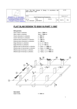
  • 1. Job Ref. Flat Slab Analysis & Design, In accordance with BS8110:PART 1:1997 Project: Section Sheet no./rev. 1 Civil & Geotechnical Engineering GEODOMISI Ltd. - Dr. Costas Sachpazis Civil & Geotechnical Engineering Consulting Company for Structural Engineering, Soil Mechanics, Rock Mechanics, Foundation Engineering & Retaining Structures. Date Calc. by Dr. C. Sachpazis Tel.: (+30) 210 5238127, 210 5711263 - Fax.:+30 210 5711461 Mobile: (+30) 6936425722 & (+44) 7585939944, costas@sachpazis.info Chk'd by Date 18/01/2014 App'd by Date FLAT SLAB DESIGN TO BS8110:PART 1:1997 Slab geometry Span of slab in x-direction; Spanx = 7200 mm Span of slab in y-direction; Spany = 7200 mm Column dimension in x-direction; lx = 400 mm Column dimension in y-direction; ly = 400 mm External column dimension in x-direction; lx1 = 250 mm External column dimension in y-direction; ly1 = 250 mm Edge dimension in x-direction; ex = lx1 / 2 = 125 mm Edge dimension in y-direction; ey = ly1 / 2 = 125 mm Effective span of internal bay in x direction; Lx = Spanx – lx = 6800 mm Effective span of internal bay in y direction; Ly = Spany – ly = 6800 mm Effective span of end bay in x direction; Lx1 = Spanx – lx / 2 = 7000 mm Effective span of end bay in y direction; Ly1 = Spany – ly / 2 = 7000 mm ex B C Span x Span x lx ey 1 A lx l y1 Sp an y lx1 ly Sp an y 2 ly 3 h Slab details Depth of slab; h = 250 mm 1
  • 2. Job Ref. Flat Slab Analysis & Design, In accordance with BS8110:PART 1:1997 Project: Section Civil & Geotechnical Engineering Consulting Company for Structural Engineering, Soil Mechanics, Rock Mechanics, Foundation Engineering & Retaining Structures. Sheet no./rev. 1 Civil & Geotechnical Engineering GEODOMISI Ltd. - Dr. Costas Sachpazis Calc. by Tel.: (+30) 210 5238127, 210 5711263 - Fax.:+30 210 5711461 Mobile: (+30) 6936425722 & (+44) 7585939944, costas@sachpazis.info Dr. C. Sachpazis Date Chk'd by Date 18/01/2014 App'd by Date 2 Characteristic strength of concrete; fcu = 35 N/mm Characteristic strength of reinforcement; fy = 500 N/mm Characteristic strength of shear reinforcement; fyv = 500 N/mm Material safety factor; γm = 1.15 2 2 Cover to bottom reinforcement; c = 20 mm Cover to top reinforcement; c’ = 20 mm Loading details 2 Characteristic dead load; Gk = 7.000 kN/m Characteristic imposed load; Qk = 5.000 kN/m 2 Dead load factor; γG = 1.4 Imposed load factor; γQ = 1.6 Total ultimate load; Nult = (Gk × γG) + (Qk × γQ) = 17.800 kN/m Moment redistribution ratio; βb = 1.0 Ratio of support moments to span moments; i = 1.0 2 DESIGN SLAB IN THE X-DIRECTION SAGGING MOMENTS End bay A-B Effective span; L = 7000 mm Depth of reinforcement; d = 200 mm Midspan moment; m = (Nult × L ) / (2 × (1 + √(1 + i)) ) = 74.823 kNm/m Support moment; m’ = i × m = 74.823 kNm/m 2 2 Design reinforcement Lever arm; 2 K’ = 0.402 × (βb – 0.4) – 0.18 × (βb – 0.4) = 0.176 2 K = m / (d × fcu) = 0.053 Compression reinforcement is not required z = min((0.5 + √(0.25 – (K / 0.9))), 0.95) × d = 187.3 mm Area of reinforcement designed; 2 As_des = m / (z × fy / γm) = 919 mm /m 2 Minimum area of reinforcement required; As_min = 0.0013 × h = 325 mm /m Area of reinforcement required; As_req = max(As_des, As_min) = 919 mm /m 2 Provide 20 dia bars @ 150 centres Area of reinforcement provided; 2 2 As_prov = π × D / (4 × s) = 2094 mm /m PASS - Span reinforcement is OK Check deflection Design service stress; fs = 2 × fy × As_req / (3 × As_prov × βb) = 146 N/mm 2 2 2 2 Modification factor; k1 = min(0.55+(477N/mm -fs)/(120×(0.9N/mm +(m/d ))),2) = 1.545 Allowable span to depth ratio; 0.9 × 26 × k1 = 36.151 Actual span to depth ratio; L / d = 35.000 2
  • 3. Job Ref. Flat Slab Analysis & Design, In accordance with BS8110:PART 1:1997 Project: Section Civil & Geotechnical Engineering Consulting Company for Structural Engineering, Soil Mechanics, Rock Mechanics, Foundation Engineering & Retaining Structures. Sheet no./rev. 1 Civil & Geotechnical Engineering GEODOMISI Ltd. - Dr. Costas Sachpazis Calc. by Tel.: (+30) 210 5238127, 210 5711263 - Fax.:+30 210 5711461 Mobile: (+30) 6936425722 & (+44) 7585939944, costas@sachpazis.info Dr. C. Sachpazis Date Chk'd by Date 18/01/2014 App'd by Date PASS - Span to depth ratio is OK Internal bay B-C Effective span; L = 6800 mm Depth of reinforcement; d = 202 mm Midspan moment; m = (Nult × L ) / (2 × (√(1 + i) + √(1 + i)) ) = 51.442 kNm/m Support moment; m’ = i × m = 51.442 kNm/m 2 2 Design reinforcement Lever arm; 2 K’ = 0.402 × (βb – 0.4) – 0.18 × (βb – 0.4) = 0.176 2 K = m / (d × fcu) = 0.036 Compression reinforcement is not required z = min((0.5 + √(0.25 – (K / 0.9))), 0.95) × d = 191.9 mm 2 Area of reinforcement designed; As_des = m / (z × fy / γm) = 617 mm /m Minimum area of reinforcement required; As_min = 0.0013 × h = 325 mm /m Area of reinforcement required; As_req = max(As_des, As_min) = 617 mm /m 2 2 Provide 16 dia bars @ 200 centres Area of reinforcement provided; 2 2 As_prov = π × D / (4 × s) = 1005 mm /m PASS - Span reinforcement is OK Check deflection 2 Design service stress; fs = 2 × fy × As_req / (3 × As_prov × βb) = 204 N/mm Modification factor; k1 = min(0.55+(477N/mm -fs)/(120×(0.9N/mm +(m/d ))),2) = 1.601 Allowable span to depth ratio; 0.9 × 26 × k1 = 37.469 Actual span to depth ratio; L / d = 33.663 2 2 2 PASS - Span to depth ratio is OK HOGGING MOMENTS – INTERNAL STRIP Penultimate column B3 Consider the reinforcement concentrated in half width strip over the support Depth of reinforcement; d’ = 200 mm Support moment; m’ = 2 × i × m = 149.646 kNm/m Lever arm; K’ = 0.402 × (βb – 0.4) – 0.18 × (βb – 0.4) = 0.176 2 2 K = m’ / (d’ × fcu) = 0.107 Compression reinforcement is not required z = min((0.5 + √(0.25 – (K / 0.9))), 0.95) × d’ = 172.5 mm Area of reinforcement required; 2 As_des = m’ / (z × fy / γm) = 1996 mm /m 2 Minimum area of reinforcement required; As_min = 0.0013 × h = 325 mm /m Area of reinforcement required; As_req = max(As_des, As_min) = 1996 mm /m 2 Provide 20 dia bars @ 150 centres Area of reinforcement provided; 2 2 As_prov = π × D / (4 × s) = 2094 mm /m PASS - Support reinforcement is OK 3
  • 4. Job Ref. Flat Slab Analysis & Design, In accordance with BS8110:PART 1:1997 Project: Section Civil & Geotechnical Engineering Consulting Company for Structural Engineering, Soil Mechanics, Rock Mechanics, Foundation Engineering & Retaining Structures. Sheet no./rev. 1 Civil & Geotechnical Engineering GEODOMISI Ltd. - Dr. Costas Sachpazis Calc. by Tel.: (+30) 210 5238127, 210 5711263 - Fax.:+30 210 5711461 Mobile: (+30) 6936425722 & (+44) 7585939944, costas@sachpazis.info Dr. C. Sachpazis Date Chk'd by Date 18/01/2014 App'd by Date Internal column C3 Consider the reinforcement concentrated in half width strip over the support Depth of reinforcement; d’ = 200 mm Support moment; m’ = 2 × i × m = 102.884 kNm/m Lever arm; K’ = 0.402 × (βb – 0.4) – 0.18 × (βb – 0.4) = 0.176 2 2 K = m’ / (d’ × fcu) = 0.073 Compression reinforcement is not required z = min((0.5 + √(0.25 – (K / 0.9))), 0.95) × d’ = 182.1 mm 2 Area of reinforcement required; As_des = m’ / (z × fy / γm) = 1300 mm /m Minimum area of reinforcement required; As_min = 0.0013 × h = 325 mm /m Area of reinforcement required; As_req = max(As_des, As_min) = 1300 mm /m 2 2 Provide 20 dia bars @ 200 centres Area of reinforcement provided; 2 2 As_prov = π × D / (4 × s) = 1571 mm /m PASS - Support reinforcement is OK HOGGING MOMENTS – EXTERNAL STRIP Penultimate column B1, B2 Consider one and a half bays of negative moment being resisted over the edge and penultimate column Width of span; B = 7200 mm Edge distance; e = 125 mm Depth of reinforcement; d’ = 200 mm Support moment; m’ = m × i ×(e + B + B / 2) / ((0.5 × B) + (0.2 × B) + e) = 158.265 kNm/m Lever arm; 2 K’ = 0.402 × (βb – 0.4) – 0.18 × (βb – 0.4) = 0.176 2 K = m’ / (d’ × fcu) = 0.113 Compression reinforcement is not required z = min((0.5 + √(0.25 – (K / 0.9))), 0.95) × d’ = 170.5 mm Area of reinforcement required; 2 As_des = m’ / (z × fy / γm) = 2134 mm /m 2 Minimum area of reinforcement required; As_min = 0.0013 × h = 325 mm /m Area of reinforcement required; As_req = max(As_des, As_min) = 2134 mm /m 2 Provide 20 dia bars @ 125 centres Area of reinforcement provided; 2 2 As_prov = π × D / (4 × s) = 2513 mm /m PASS - Support reinforcement is OK Internal column C1, C2 Consider one and a half bays of negative moment being resisted over the edge and penultimate column Width of span; B = 7200 mm Edge distance; e = 125 mm Depth of reinforcement; d’ = 200 mm Support moment; m’ = m × i ×(e + B + B / 2) / ((0.5 × B) + (0.2 × B) + e) = 108.810 kNm/m 4
  • 5. Job Ref. Flat Slab Analysis & Design, In accordance with BS8110:PART 1:1997 Project: Section Civil & Geotechnical Engineering Consulting Company for Structural Engineering, Soil Mechanics, Rock Mechanics, Foundation Engineering & Retaining Structures. Tel.: (+30) 210 5238127, 210 5711263 - Fax.:+30 210 5711461 Mobile: (+30) 6936425722 & (+44) 7585939944, costas@sachpazis.info Sheet no./rev. 1 Civil & Geotechnical Engineering GEODOMISI Ltd. - Dr. Costas Sachpazis Calc. by Dr. C. Sachpazis Lever arm; Date Chk'd by Date 18/01/2014 App'd by Date 2 K’ = 0.402 × (βb – 0.4) – 0.18 × (βb – 0.4) = 0.176 2 K = m’ / (d’ × fcu) = 0.078 Compression reinforcement is not required z = min((0.5 + √(0.25 – (K / 0.9))), 0.95) × d’ = 180.9 mm 2 Area of reinforcement required; As_des = m’ / (z × fy / γm) = 1383 mm /m Minimum area of reinforcement required; As_min = 0.0013 × h = 325 mm /m Area of reinforcement required; As_req = max(As_des, As_min) = 1383 mm /m 2 2 Provide 20 dia bars @ 200 centres Area of reinforcement provided; 2 2 As_prov = π × D / (4 × s) = 1571 mm /m PASS - Support reinforcement is OK Corner column A1 Depth of reinforcement; d’ = 206 mm Total load on column; S = ((Spanx / 2) + ex) × ((Spany / 2) + ey) × Nult = 247 kN Area of column head; A = lx × ly1 = 0.100 m Support moment; m’ = S × (1 – (Nult × A / S) ) / 2 = 99.639 kNm/m Lever arm; K’ = 0.402 × (βb – 0.4) – 0.18 × (βb – 0.4) = 0.176 2 1/3 2 2 K = m’ / (d’ × fcu) = 0.067 Compression reinforcement is not required z = min((0.5 + √(0.25 – (K / 0.9))), 0.95) × d’ = 189.3 mm 2 Area of reinforcement required; As_des = m’ / (z × fy / γm) = 1211 mm /m Minimum area of reinforcement required; As_min = 0.0013 × h = 325 mm /m Area of reinforcement required; As_req = max(As_des, As_min) = 1211 mm /m 2 2 Provide 16 dia bars @ 150 centres Area of reinforcement provided; 2 2 As_prov = π × D / (4 × s) = 1340 mm /m PASS - Support reinforcement is OK Edge column A2, A3 Depth of reinforcement; d’ = 202 mm Total load on column; S = Spanx × (Spany / 2 + ey) × Nult = 477 kN Area of column head; A = lx1 × ly = 0.100 m Support moment; m’ = S × (1 – (Nult × A / S) ) / 5.14 = 78.476 kNm/m Lever arm; K’ = 0.402 × (βb – 0.4) – 0.18 × (βb – 0.4) = 0.176 2 1/3 2 2 K = m’ / (d’ × fcu) = 0.055 Compression reinforcement is not required z = min((0.5 + √(0.25 – (K / 0.9))), 0.95) × d’ = 188.8 mm Area of reinforcement required; 2 As_des = m’ / (z × fy / γm) = 956 mm /m 2 Minimum area of reinforcement required; As_min = 0.0013 × h = 325 mm /m Area of reinforcement required; As_req = max(As_des, As_min) = 956 mm /m 2 Provide 16 dia bars @ 175 centres Area of reinforcement provided; 2 2 As_prov = π × D / (4 × s) = 1149 mm /m 5
  • 6. Job Ref. Flat Slab Analysis & Design, In accordance with BS8110:PART 1:1997 Project: Section Civil & Geotechnical Engineering Consulting Company for Structural Engineering, Soil Mechanics, Rock Mechanics, Foundation Engineering & Retaining Structures. Tel.: (+30) 210 5238127, 210 5711263 - Fax.:+30 210 5711461 Mobile: (+30) 6936425722 & (+44) 7585939944, costas@sachpazis.info Sheet no./rev. 1 Civil & Geotechnical Engineering GEODOMISI Ltd. - Dr. Costas Sachpazis Calc. by Dr. C. Sachpazis Date Chk'd by Date 18/01/2014 App'd by Date PASS - Support reinforcement is OK Between columns 1-2, 2-3 Around the perimeter between the column heads provide a minimum of 50% of the required end span bottom reinforcement. Area of reinforcement required; 2 As_req = Asx1 / 2 = 1047 mm /m Provide 16 dia bars @ 150 centres - 'U' bars with 1600 mm long legs Area of reinforcement provided; 2 2 As_prov = π × D / (4 × s) = 1340 mm /m PASS - Edge reinforcement is OK Distribution reinforcement Provide 12 dia bars @ 300 centres Area of reinforcement provided; 2 2 As_prov = π × D / (4 × s) = 377 mm /m DESIGN SLAB IN THE Y-DIRECTION SAGGING MOMENTS End bay 1-2 Effective span; L = 7000 mm Depth of reinforcement; d = 220 mm Midspan moment; m = (Nult × L ) / (2 × (1 + √(1 + i)) ) = 74.823 kNm/m Support moment; m’ = i × m = 74.823 kNm/m 2 2 Design reinforcement Lever arm; 2 K’ = 0.402 × (βb – 0.4) – 0.18 × (βb – 0.4) = 0.176 2 K = m / (d × fcu) = 0.044 Compression reinforcement is not required z = min((0.5 + √(0.25 – (K / 0.9))), 0.95) × d = 208.6 mm 2 Area of reinforcement designed; As_des = m / (z × fy / γm) = 825 mm /m Minimum area of reinforcement required; As_min = 0.0013 × h = 325 mm /m Area of reinforcement required; As_req = max(As_des, As_min) = 825 mm /m 2 2 Provide 20 dia bars @ 200 centres Area of reinforcement provided; 2 2 As_prov = π × D / (4 × s) = 1571 mm /m PASS - Span reinforcement is OK Check deflection 2 Design service stress; fs = 2 × fy × As_req / (3 × As_prov × βb) = 175 N/mm Modification factor; k1 = min(0.55+(477N/mm -fs)/(120×(0.9N/mm +(m/d ))),2) = 1.579 Allowable span to depth ratio; 0.9 × 26 × k1 = 36.942 Actual span to depth ratio; L / d = 31.818 2 2 2 PASS - Span to depth ratio is OK Internal bay 2-3 Effective span; L = 6800 mm 6
  • 7. Job Ref. Flat Slab Analysis & Design, In accordance with BS8110:PART 1:1997 Project: Section Civil & Geotechnical Engineering Consulting Company for Structural Engineering, Soil Mechanics, Rock Mechanics, Foundation Engineering & Retaining Structures. Sheet no./rev. 1 Civil & Geotechnical Engineering GEODOMISI Ltd. - Dr. Costas Sachpazis Calc. by Tel.: (+30) 210 5238127, 210 5711263 - Fax.:+30 210 5711461 Mobile: (+30) 6936425722 & (+44) 7585939944, costas@sachpazis.info Dr. C. Sachpazis Date Chk'd by Date 18/01/2014 App'd by Date Depth of reinforcement; d = 222 mm Midspan moment; m = (Nult × L ) / (2 × (√(1 + i) + √(1 + i)) ) = 51.442 kNm/m Support moment; m’ = i × m = 51.442 kNm/m 2 2 Design reinforcement Lever arm; 2 K’ = 0.402 × (βb – 0.4) – 0.18 × (βb – 0.4) = 0.176 2 K = m / (d × fcu) = 0.030 Compression reinforcement is not required z = min((0.5 + √(0.25 – (K / 0.9))), 0.95) × d = 210.9 mm 2 Area of reinforcement designed; As_des = m / (z × fy / γm) = 561 mm /m Minimum area of reinforcement required; As_min = 0.0013 × h = 325 mm /m Area of reinforcement required; As_req = max(As_des, As_min) = 561 mm /m 2 2 Provide 16 dia bars @ 200 centres Area of reinforcement provided; 2 2 As_prov = π × D / (4 × s) = 1005 mm /m PASS - Span reinforcement is OK Check deflection 2 Design service stress; fs = 2 × fy × As_req / (3 × As_prov × βb) = 186 N/mm Modification factor; k1 = min(0.55+(477N/mm -fs)/(120×(0.9N/mm +(m/d ))),2) = 1.798 Allowable span to depth ratio; 0.9 × 26 × k1 = 42.062 Actual span to depth ratio; L / d = 30.631 2 2 2 PASS - Span to depth ratio is OK HOGGING MOMENTS – INTERNAL STRIP Penultimate column C2 Consider the reinforcement concentrated in half width strip over the support Depth of reinforcement; d’ = 220 mm Support moment; m’ = 2 × i × m = 149.646 kNm/m Lever arm; K’ = 0.402 × (βb – 0.4) – 0.18 × (βb – 0.4) = 0.176 2 2 K = m’ / (d’ × fcu) = 0.088 Compression reinforcement is not required z = min((0.5 + √(0.25 – (K / 0.9))), 0.95) × d’ = 195.7 mm Area of reinforcement required; 2 As_des = m’ / (z × fy / γm) = 1758 mm /m 2 Minimum area of reinforcement required; As_min = 0.0013 × h = 325 mm /m Area of reinforcement required; As_req = max(As_des, As_min) = 1758 mm /m 2 Provide 20 dia bars @ 150 centres Area of reinforcement provided; 2 2 As_prov = π × D / (4 × s) = 2094 mm /m PASS - Support reinforcement is OK Internal column C3 Consider the reinforcement concentrated in half width strip over the support Depth of reinforcement; d’ = 220 mm 7
  • 8. Job Ref. Flat Slab Analysis & Design, In accordance with BS8110:PART 1:1997 Project: Section Civil & Geotechnical Engineering Consulting Company for Structural Engineering, Soil Mechanics, Rock Mechanics, Foundation Engineering & Retaining Structures. Sheet no./rev. 1 Civil & Geotechnical Engineering GEODOMISI Ltd. - Dr. Costas Sachpazis Calc. by Tel.: (+30) 210 5238127, 210 5711263 - Fax.:+30 210 5711461 Mobile: (+30) 6936425722 & (+44) 7585939944, costas@sachpazis.info Dr. C. Sachpazis Date Chk'd by Date 18/01/2014 App'd by Support moment; m’ = 2 × i × m = 102.884 kNm/m Lever arm; Date K’ = 0.402 × (βb – 0.4) – 0.18 × (βb – 0.4) = 0.176 2 2 K = m’ / (d’ × fcu) = 0.061 Compression reinforcement is not required z = min((0.5 + √(0.25 – (K / 0.9))), 0.95) × d’ = 204.0 mm Area of reinforcement required; 2 As_des = m’ / (z × fy / γm) = 1160 mm /m 2 Minimum area of reinforcement required; As_min = 0.0013 × h = 325 mm /m Area of reinforcement required; As_req = max(As_des, As_min) = 1160 mm /m 2 Provide 20 dia bars @ 200 centres Area of reinforcement provided; 2 2 As_prov = π × D / (4 × s) = 1571 mm /m PASS - Support reinforcement is OK HOGGING MOMENTS – EXTERNAL STRIP Penultimate column A2, B2 Consider one and a half bays of negative moment being resisted over the edge and penultimate column Width of span; B = 7200 mm Edge distance; e = 125 mm Depth of reinforcement; d’ = 220 mm Support moment; m’ = m × i ×(e + B + B / 2) / ((0.5 × B) + (0.2 × B) + e) = 158.265 kNm/m Lever arm; 2 K’ = 0.402 × (βb – 0.4) – 0.18 × (βb – 0.4) = 0.176 2 K = m’ / (d’ × fcu) = 0.093 Compression reinforcement is not required z = min((0.5 + √(0.25 – (K / 0.9))), 0.95) × d’ = 194.1 mm Area of reinforcement required; 2 As_des = m’ / (z × fy / γm) = 1875 mm /m 2 Minimum area of reinforcement required; As_min = 0.0013 × h = 325 mm /m Area of reinforcement required; As_req = max(As_des, As_min) = 1875 mm /m 2 Provide 20 dia bars @ 150 centres Area of reinforcement provided; 2 2 As_prov = π × D / (4 × s) = 2094 mm /m PASS - Support reinforcement is OK Internal column A3, B3 Consider one and a half bays of negative moment being resisted over the edge and penultimate column Width of span; B = 7200 mm Edge distance; e = 125 mm Depth of reinforcement; d’ = 220 mm Support moment; m’ = m × i ×(e + B + B / 2) / ((0.5 × B) + (0.2 × B) + e) = 108.810 kNm/m Lever arm; 2 K’ = 0.402 × (βb – 0.4) – 0.18 × (βb – 0.4) = 0.176 2 K = m’ / (d’ × fcu) = 0.064 8
  • 9. Job Ref. Flat Slab Analysis & Design, In accordance with BS8110:PART 1:1997 Project: Section Civil & Geotechnical Engineering Consulting Company for Structural Engineering, Soil Mechanics, Rock Mechanics, Foundation Engineering & Retaining Structures. Tel.: (+30) 210 5238127, 210 5711263 - Fax.:+30 210 5711461 Mobile: (+30) 6936425722 & (+44) 7585939944, costas@sachpazis.info Sheet no./rev. 1 Civil & Geotechnical Engineering GEODOMISI Ltd. - Dr. Costas Sachpazis Calc. by Dr. C. Sachpazis Date Chk'd by Date 18/01/2014 App'd by Date Compression reinforcement is not required z = min((0.5 + √(0.25 – (K / 0.9))), 0.95) × d’ = 203.0 mm 2 Area of reinforcement required; As_des = m’ / (z × fy / γm) = 1233 mm /m Minimum area of reinforcement required; As_min = 0.0013 × h = 325 mm /m Area of reinforcement required; As_req = max(As_des, As_min) = 1233 mm /m 2 2 Provide 20 dia bars @ 200 centres Area of reinforcement provided; 2 2 As_prov = π × D / (4 × s) = 1571 mm /m PASS - Support reinforcement is OK Edge column B1, C1 Depth of reinforcement; d’ = 222 mm Total load on column; S = (Spanx / 2 + ex) × Spany × Nult = 477 kN Area of column head; A = ly1 × lx = 0.100 m Support moment; m’ = S × (1 – (Nult × A / S) ) / 5.14 = 78.476 kNm/m Lever arm; K’ = 0.402 × (βb – 0.4) – 0.18 × (βb – 0.4) = 0.176 2 1/3 2 2 K = m’ / (d’ × fcu) = 0.045 Compression reinforcement is not required z = min((0.5 + √(0.25 – (K / 0.9))), 0.95) × d’ = 210.1 mm 2 Area of reinforcement required; As_des = m’ / (z × fy / γm) = 859 mm /m Minimum area of reinforcement required; As_min = 0.0013 × h = 325 mm /m Area of reinforcement required; As_req = max(As_des, As_min) = 859 mm /m 2 2 Provide 16 dia bars @ 175 centres Area of reinforcement provided; 2 2 As_prov = π × D / (4 × s) = 1149 mm /m PASS - Support reinforcement is OK Between columns A-B, B-C Around the perimeter between the column heads provide a minimum of 50% of the required end span bottom reinforcement. Area of reinforcement required; 2 As_req = Asy1 / 2 = 785 mm /m Provide 16 dia bars @ 200 centres - 'U' bars with 1600 mm long legs Area of reinforcement provided; 2 2 As_prov = π × D / (4 × s) = 1005 mm /m PASS - Edge reinforcement is OK PUNCHING SHEAR Corner column A1 Design shear transferred to column; Vt = ((0.45 × Spanx) + ex) × ((0.45 × Spany) + ey) × Nult = 202 kN Design effective shear transferred to column; Veff = 1.25 × Vt = 252 kN Area of tension steel in x-direction; Asx_ten = Ascorner = 1340 mm /m Area of tension steel in y-direction; Asy_ten = Ascorner = 1340 mm /m Column perimeter; uc = lx1 + ly = 650 mm Average effective depth of reinforcement; d = h – c - φp = 214 mm 2 2 9
  • 10. Job Ref. Flat Slab Analysis & Design, In accordance with BS8110:PART 1:1997 Project: Section Civil & Geotechnical Engineering Consulting Company for Structural Engineering, Soil Mechanics, Rock Mechanics, Foundation Engineering & Retaining Structures. Tel.: (+30) 210 5238127, 210 5711263 - Fax.:+30 210 5711461 Mobile: (+30) 6936425722 & (+44) 7585939944, costas@sachpazis.info Sheet no./rev. 1 Civil & Geotechnical Engineering GEODOMISI Ltd. - Dr. Costas Sachpazis Date Calc. by Dr. C. Sachpazis Chk'd by Date 18/01/2014 Maximum allowable shear stress; vmax = min(0.8 × √(fcu), 5) = 4.733 N/mm Design shear stress at column perimeter; v0 = Veff / (uc × d) = 1.811 N/mm App'd by Date 2 2 PASS - Maximum concrete shear stress not exceeded at column perimeter Shear reinforcement at a perimeter of 1.50d - (321 mm) Length of shear perimeter; u = uc + (2 × (kx × ky) × k × d) = 1292 mm Area of tension steel at shear perimeter; As_ten = (ky × (px + (kx × k × d)) × Asy_ten) + (kx × (py + (ky × k × d)) × Asx_ten) As_ten = 1731 mm 2 Design concrete shear stress; 1/3 1/3 1/4 vc=(min(fcu,40)/25) ×0.79×min(100×As_ten/(u×d),3) ×max(400/d,1) /1.25 2 vc = 0.707 N/mm 2 Nominal design shear stress at perimeter; v = Veff / (u × d) = 0.911 N/mm Shear reinforcement required at perimeter; Asv_req = (v - vc) × u × d / (0.95 × fyv) = 119 mm vc < v <= 1.6 × vc 2 Shear reinforcement at a perimeter of 2.25d - (482 mm) Length of shear perimeter; u = uc + (2 × (kx × ky) × k × d) = 1613 mm Area of tension steel at shear perimeter; As_ten = (ky × (px + (kx × k × d)) × Asy_ten) + (kx × (py + (ky × k × d)) × Asx_ten) As_ten = 2161 mm 2 Design concrete shear stress; 1/3 1/3 1/4 vc=(min(fcu,40)/25) ×0.79×min(100×As_ten/(u×d),3) ×max(400/d,1) /1.25 2 vc = 0.707 N/mm Nominal design shear stress at perimeter; 2 v = Veff / (u × d) = 0.730 N/mm vc < v <= 1.6 × vc Shear reinforcement required at perimeter; 2 Asv_req = (v - vc) × u × d / (0.95 × fyv) = 16 mm Shear reinforcement at a perimeter of 3.00d - (642 mm) Length of shear perimeter; u = uc + (2 × (kx × ky) × k × d) = 1934 mm Area of tension steel at shear perimeter; As_ten = (ky × (px + (kx × k × d)) × Asy_ten) + (kx × (py + (ky × k × d)) × Asx_ten) As_ten = 2592 mm 2 Design concrete shear stress; 1/3 1/3 1/4 vc=(min(fcu,40)/25) ×0.79×min(100×As_ten/(u×d),3) ×max(400/d,1) /1.25 2 vc = 0.707 N/mm Nominal design shear stress at perimeter; 2 v = Veff / (u × d) = 0.609 N/mm v < vc no shear reinforcement required Penultimate edge column A2 Design shear transferred to column; Vt = ((0.45 × Spanx) + ex) × (1.05 × Spany) × Nult = 453 kN Design effective shear transferred to column; Veff = 1.4 × Vt = 634 kN Area of tension steel in x-direction; Asx_ten = Asx_edge = 1148 mm /m 2 10
  • 11. Job Ref. Flat Slab Analysis & Design, In accordance with BS8110:PART 1:1997 Project: Section Civil & Geotechnical Engineering Consulting Company for Structural Engineering, Soil Mechanics, Rock Mechanics, Foundation Engineering & Retaining Structures. Tel.: (+30) 210 5238127, 210 5711263 - Fax.:+30 210 5711461 Mobile: (+30) 6936425722 & (+44) 7585939944, costas@sachpazis.info Sheet no./rev. 1 Civil & Geotechnical Engineering GEODOMISI Ltd. - Dr. Costas Sachpazis Date Calc. by Dr. C. Sachpazis Chk'd by Date 18/01/2014 App'd by Date 2 Area of tension steel in y-direction; Asy_ten = Asy1e = 2094 mm /m Column perimeter; uc = (2 × lx1)+ ly = 900 mm Average effective depth of reinforcement; d = h – c - φp = 214 mm Maximum allowable shear stress; vmax = min(0.8 × √(fcu), 5) = 4.733 N/mm Design shear stress at column perimeter; v0 = Veff / (uc × d) = 3.292 N/mm 2 2 PASS - Maximum concrete shear stress not exceeded at column perimeter Shear reinforcement at a perimeter of 1.50d - (321 mm) Length of shear perimeter; u = uc + (2 × (kx × ky) × k × d) = 2184 mm Area of tension steel at shear perimeter; As_ten = (ky × (px + (kx × k × d)) × Asy_ten) + (kx × (py + (ky × k × d)) × Asx_ten) As_ten = 3588 mm 2 Design concrete shear stress; 1/3 1/3 1/4 vc=(min(fcu,40)/25) ×0.79×min(100×As_ten/(u×d),3) ×max(400/d,1) /1.25 2 vc = 0.757 N/mm Nominal design shear stress at perimeter; 2 v = Veff / (u × d) = 1.356 N/mm 1.6 × vc < v <= 2 × vc Shear reinforcement required at perimeter; Asv_req = 5 × ((0.7 × v) - vc) × u × d / (0.95 × fyv) = 947 mm 2 Shear reinforcement at a perimeter of 2.25d - (482 mm) Length of shear perimeter; u = uc + (2 × (kx × ky) × k × d) = 2826 mm Area of tension steel at shear perimeter; As_ten = (ky × (px + (kx × k × d)) × Asy_ten) + (kx × (py + (ky × k × d)) × Asx_ten) As_ten = 4628 mm 2 Design concrete shear stress; 1/3 1/3 1/4 vc=(min(fcu,40)/25) ×0.79×min(100×As_ten/(u×d),3) ×max(400/d,1) /1.25 2 vc = 0.756 N/mm Nominal design shear stress at perimeter; 2 v = Veff / (u × d) = 1.048 N/mm vc < v <= 1.6 × vc Shear reinforcement required at perimeter; 2 Asv_req = (v - vc) × u × d / (0.95 × fyv) = 372 mm Shear reinforcement at a perimeter of 3.00d - (642 mm) Length of shear perimeter; u = uc + (2 × (kx × ky) × k × d) = 3468 mm Area of tension steel at shear perimeter; As_ten = (ky × (px + (kx × k × d)) × Asy_ten) + (kx × (py + (ky × k × d)) × Asx_ten) As_ten = 5669 mm 2 Design concrete shear stress; 1/3 1/3 1/4 vc=(min(fcu,40)/25) ×0.79×min(100×As_ten/(u×d),3) ×max(400/d,1) /1.25 2 vc = 0.756 N/mm 2 Nominal design shear stress at perimeter; v = Veff / (u × d) = 0.854 N/mm Shear reinforcement required at perimeter; Asv_req = (v - vc) × u × d / (0.95 × fyv) = 154 mm vc < v <= 1.6 × vc 2 11
  • 12. Job Ref. Flat Slab Analysis & Design, In accordance with BS8110:PART 1:1997 Project: Section Civil & Geotechnical Engineering Consulting Company for Structural Engineering, Soil Mechanics, Rock Mechanics, Foundation Engineering & Retaining Structures. Sheet no./rev. 1 Civil & Geotechnical Engineering GEODOMISI Ltd. - Dr. Costas Sachpazis Date Calc. by Tel.: (+30) 210 5238127, 210 5711263 - Fax.:+30 210 5711461 Mobile: (+30) 6936425722 & (+44) 7585939944, costas@sachpazis.info Dr. C. Sachpazis Chk'd by Date 18/01/2014 App'd by Date Shear reinforcement at a perimeter of 3.75d - (803 mm) Length of shear perimeter; u = uc + (2 × (kx × ky) × k × d) = 4110 mm Area of tension steel at shear perimeter; As_ten = (ky × (px + (kx × k × d)) × Asy_ten) + (kx × (py + (ky × k × d)) × Asx_ten) As_ten = 6710 mm 2 Design concrete shear stress; 1/3 1/3 1/4 vc=(min(fcu,40)/25) ×0.79×min(100×As_ten/(u×d),3) ×max(400/d,1) /1.25 2 vc = 0.755 N/mm Nominal design shear stress at perimeter; 2 v = Veff / (u × d) = 0.721 N/mm v < vc no shear reinforcement required Internal edge column A3 Design shear transferred to column; Vt = ((0.45 × Spanx) + ex) × Spany × Nult = 431 kN Design effective shear transferred to column; Veff = 1.4 × Vt = 604 kN Area of tension steel in x-direction; Asx_ten = Asx_edge = 1148 mm /m 2 2 Area of tension steel in y-direction; Asy_ten = Asye = 1570 mm /m Column perimeter; uc = (2 × lx1)+ ly = 900 mm Average effective depth of reinforcement; d = h – c - φp = 214 mm Maximum allowable shear stress; vmax = min(0.8 × √(fcu), 5) = 4.733 N/mm Design shear stress at column perimeter; v0 = Veff / (uc × d) = 3.135 N/mm 2 2 PASS - Maximum concrete shear stress not exceeded at column perimeter Shear reinforcement at a perimeter of 1.50d - (321 mm) Length of shear perimeter; u = uc + (2 × (kx × ky) × k × d) = 2184 mm Area of tension steel at shear perimeter; As_ten = (ky × (px + (kx × k × d)) × Asy_ten) + (kx × (py + (ky × k × d)) × Asx_ten) As_ten = 2989 mm 2 Design concrete shear stress; 1/3 1/3 1/4 vc=(min(fcu,40)/25) ×0.79×min(100×As_ten/(u×d),3) ×max(400/d,1) /1.25 2 vc = 0.712 N/mm 2 Nominal design shear stress at perimeter; v = Veff / (u × d) = 1.292 N/mm Shear reinforcement required at perimeter; Asv_req = 5 × ((0.7 × v) - vc) × u × d / (0.95 × fyv) = 945 mm 1.6 × vc < v <= 2 × vc 2 Shear reinforcement at a perimeter of 2.25d - (482 mm) Length of shear perimeter; u = uc + (2 × (kx × ky) × k × d) = 2826 mm Area of tension steel at shear perimeter; As_ten = (ky × (px + (kx × k × d)) × Asy_ten) + (kx × (py + (ky × k × d)) × Asx_ten) As_ten = 3862 mm 2 Design concrete shear stress; 1/3 1/3 1/4 vc=(min(fcu,40)/25) ×0.79×min(100×As_ten/(u×d),3) ×max(400/d,1) /1.25 2 vc = 0.712 N/mm 12
  • 13. Job Ref. Flat Slab Analysis & Design, In accordance with BS8110:PART 1:1997 Project: Section Civil & Geotechnical Engineering Consulting Company for Structural Engineering, Soil Mechanics, Rock Mechanics, Foundation Engineering & Retaining Structures. Tel.: (+30) 210 5238127, 210 5711263 - Fax.:+30 210 5711461 Mobile: (+30) 6936425722 & (+44) 7585939944, costas@sachpazis.info Sheet no./rev. 1 Civil & Geotechnical Engineering GEODOMISI Ltd. - Dr. Costas Sachpazis Calc. by Dr. C. Sachpazis Date Chk'd by Date 18/01/2014 Nominal design shear stress at perimeter; App'd by Date 2 v = Veff / (u × d) = 0.998 N/mm vc < v <= 1.6 × vc Shear reinforcement required at perimeter; 2 Asv_req = (v - vc) × u × d / (0.95 × fyv) = 365 mm Shear reinforcement at a perimeter of 3.00d - (642 mm) Length of shear perimeter; u = uc + (2 × (kx × ky) × k × d) = 3468 mm Area of tension steel at shear perimeter; As_ten = (ky × (px + (kx × k × d)) × Asy_ten) + (kx × (py + (ky × k × d)) × Asx_ten) As_ten = 4734 mm2 Design concrete shear stress; 1/3 1/3 1/4 vc=(min(fcu,40)/25) ×0.79×min(100×As_ten/(u×d),3) ×max(400/d,1) /1.25 2 vc = 0.712 N/mm Nominal design shear stress at perimeter; 2 v = Veff / (u × d) = 0.814 N/mm vc < v <= 1.6 × vc Shear reinforcement required at perimeter; 2 Asv_req = (v - vc) × u × d / (0.95 × fyv) = 159 mm Shear reinforcement at a perimeter of 3.75d - (803 mm) Length of shear perimeter; u = uc + (2 × (kx × ky) × k × d) = 4110 mm Area of tension steel at shear perimeter; As_ten = (ky × (px + (kx × k × d)) × Asy_ten) + (kx × (py + (ky × k × d)) × Asx_ten) As_ten = 5607 mm 2 Design concrete shear stress; 1/3 1/3 1/4 vc=(min(fcu,40)/25) ×0.79×min(100×As_ten/(u×d),3) ×max(400/d,1) /1.25 2 vc = 0.711 N/mm Nominal design shear stress at perimeter; 2 v = Veff / (u × d) = 0.686 N/mm v < vc no shear reinforcement required Penultimate edge column B1 Design shear transferred to column; Vt = (1.05 × Spanx) × ((0.45 × Spany) + ey) × Nult = 453 kN Design effective shear transferred to column; Veff = 1.4 × Vt = 634 kN Area of tension steel in x-direction; Asx_ten = Asx1e = 2513 mm /m Area of tension steel in y-direction; Asy_ten = Asy_edge = 1148 mm /m 2 2 Column perimeter; uc = lx + (2 × ly1) = 900 mm Average effective depth of reinforcement; d = h – c - φp = 214 mm Maximum allowable shear stress; vmax = min(0.8 × √(fcu), 5) = 4.733 N/mm Design shear stress at column perimeter; v0 = Veff / (uc × d) = 3.292 N/mm 2 2 PASS - Maximum concrete shear stress not exceeded at column perimeter Shear reinforcement at a perimeter of 1.50d - (321 mm) Length of shear perimeter; u = uc + (2 × (kx × ky) × k × d) = 2184 mm Area of tension steel at shear perimeter; As_ten = (ky × (px + (kx × k × d)) × Asy_ten) + (kx × (py + (ky × k × d)) × Asx_ten) As_ten = 4066 mm 2 13
  • 14. Job Ref. Flat Slab Analysis & Design, In accordance with BS8110:PART 1:1997 Project: Section Civil & Geotechnical Engineering Consulting Company for Structural Engineering, Soil Mechanics, Rock Mechanics, Foundation Engineering & Retaining Structures. Tel.: (+30) 210 5238127, 210 5711263 - Fax.:+30 210 5711461 Mobile: (+30) 6936425722 & (+44) 7585939944, costas@sachpazis.info Sheet no./rev. 1 Civil & Geotechnical Engineering GEODOMISI Ltd. - Dr. Costas Sachpazis Calc. by Dr. C. Sachpazis Date Chk'd by Date 18/01/2014 App'd by Date Design concrete shear stress; 1/3 1/3 1/4 vc=(min(fcu,40)/25) ×0.79×min(100×As_ten/(u×d),3) ×max(400/d,1) /1.25 2 vc = 0.789 N/mm Nominal design shear stress at perimeter; 2 v = Veff / (u × d) = 1.356 N/mm 1.6 × vc < v <= 2 × vc Shear reinforcement required at perimeter; Asv_req = 5 × ((0.7 × v) - vc) × u × d / (0.95 × fyv) = 789 mm 2 Shear reinforcement at a perimeter of 2.25d - (482 mm) Length of shear perimeter; u = uc + (2 × (kx × ky) × k × d) = 2826 mm Area of tension steel at shear perimeter; As_ten = (ky × (px + (kx × k × d)) × Asy_ten) + (kx × (py + (ky × k × d)) × Asx_ten) As_ten = 5241 mm 2 Design concrete shear stress; 1/3 1/3 1/4 vc=(min(fcu,40)/25) ×0.79×min(100×As_ten/(u×d),3) ×max(400/d,1) /1.25 2 vc = 0.788 N/mm Nominal design shear stress at perimeter; 2 v = Veff / (u × d) = 1.048 N/mm vc < v <= 1.6 × vc Shear reinforcement required at perimeter; 2 Asv_req = (v - vc) × u × d / (0.95 × fyv) = 331 mm Shear reinforcement at a perimeter of 3.00d - (642 mm) Length of shear perimeter; u = uc + (2 × (kx × ky) × k × d) = 3468 mm Area of tension steel at shear perimeter; As_ten = (ky × (px + (kx × k × d)) × Asy_ten) + (kx × (py + (ky × k × d)) × Asx_ten) As_ten = 6416 mm 2 Design concrete shear stress; 1/3 1/3 1/4 vc=(min(fcu,40)/25) ×0.79×min(100×As_ten/(u×d),3) ×max(400/d,1) /1.25 2 vc = 0.788 N/mm Nominal design shear stress at perimeter; 2 v = Veff / (u × d) = 0.854 N/mm vc < v <= 1.6 × vc Shear reinforcement required at perimeter; 2 Asv_req = (v - vc) × u × d / (0.95 × fyv) = 104 mm Shear reinforcement at a perimeter of 3.75d - (803 mm) Length of shear perimeter; u = uc + (2 × (kx × ky) × k × d) = 4110 mm Area of tension steel at shear perimeter; As_ten = (ky × (px + (kx × k × d)) × Asy_ten) + (kx × (py + (ky × k × d)) × Asx_ten) As_ten = 7592 mm 2 Design concrete shear stress; 1/3 1/3 1/4 vc=(min(fcu,40)/25) ×0.79×min(100×As_ten/(u×d),3) ×max(400/d,1) /1.25 2 vc = 0.787 N/mm Nominal design shear stress at perimeter; 2 v = Veff / (u × d) = 0.721 N/mm v < vc no shear reinforcement required 14
  • 15. Job Ref. Flat Slab Analysis & Design, In accordance with BS8110:PART 1:1997 Project: Section Civil & Geotechnical Engineering Consulting Company for Structural Engineering, Soil Mechanics, Rock Mechanics, Foundation Engineering & Retaining Structures. Tel.: (+30) 210 5238127, 210 5711263 - Fax.:+30 210 5711461 Mobile: (+30) 6936425722 & (+44) 7585939944, costas@sachpazis.info Sheet no./rev. 1 Civil & Geotechnical Engineering GEODOMISI Ltd. - Dr. Costas Sachpazis Calc. by Dr. C. Sachpazis Date Chk'd by Date 18/01/2014 App'd by Date Penultimate central column B2 Design shear transferred to column; Vt = (1.05 × Spanx) × (1.05 × Spany) × Nult = 1017 kN Design effective shear transferred to column; Veff = 1.15 × Vt = 1170 kN Area of tension steel in x-direction; Asx_ten = Asx1e = 2513 mm /m Area of tension steel in y-direction; Asy_ten = Asy1e = 2094 mm /m 2 2 Column perimeter; uc = 2 × (lx + ly) = 1600 mm Average effective depth of reinforcement; d = h – c - φp = 214 mm Maximum allowable shear stress; vmax = min(0.8 × √(fcu), 5) = 4.733 N/mm Design shear stress at column perimeter; v0 = Veff / (uc × d) = 3.417 N/mm 2 2 PASS - Maximum concrete shear stress not exceeded at column perimeter Shear reinforcement at a perimeter of 1.50d - (321 mm) Length of shear perimeter; u = uc + (2 × (kx × ky) × k × d) = 4168 mm Area of tension steel at shear perimeter; As_ten = (ky × (px + (kx × k × d)) × Asy_ten) + (kx × (py + (ky × k × d)) × Asx_ten) As_ten = 9601 mm2 Design concrete shear stress; 1/3 1/3 1/4 vc=(min(fcu,40)/25) ×0.79×min(100×As_ten/(u×d),3) ×max(400/d,1) /1.25 2 vc = 0.847 N/mm Nominal design shear stress at perimeter; 2 v = Veff / (u × d) = 1.312 N/mm vc < v <= 1.6 × vc Shear reinforcement required at perimeter; 2 Asv_req = (v - vc) × u × d / (0.95 × fyv) = 872 mm Shear reinforcement at a perimeter of 2.25d - (482 mm) Length of shear perimeter; u = uc + (2 × (kx × ky) × k × d) = 5452 mm Area of tension steel at shear perimeter; As_ten = (ky × (px + (kx × k × d)) × Asy_ten) + (kx × (py + (ky × k × d)) × Asx_ten) As_ten = 12559 mm 2 Design concrete shear stress; 1/3 1/3 1/4 vc=(min(fcu,40)/25) ×0.79×min(100×As_ten/(u×d),3) ×max(400/d,1) /1.25 2 vc = 0.847 N/mm Nominal design shear stress at perimeter; 2 v = Veff / (u × d) = 1.003 N/mm vc < v <= 1.6 × vc Shear reinforcement required at perimeter; 2 Asv_req = (v - vc) × u × d / (0.95 × fyv) = 382 mm Shear reinforcement at a perimeter of 3.00d - (642 mm) Length of shear perimeter; u = uc + (2 × (kx × ky) × k × d) = 6736 mm Area of tension steel at shear perimeter; As_ten = (ky × (px + (kx × k × d)) × Asy_ten) + (kx × (py + (ky × k × d)) × Asx_ten) As_ten = 15516 mm 2 Design concrete shear stress; 1/3 1/3 1/4 vc=(min(fcu,40)/25) ×0.79×min(100×As_ten/(u×d),3) ×max(400/d,1) /1.25 15
  • 16. Job Ref. Flat Slab Analysis & Design, In accordance with BS8110:PART 1:1997 Project: Section Civil & Geotechnical Engineering Consulting Company for Structural Engineering, Soil Mechanics, Rock Mechanics, Foundation Engineering & Retaining Structures. Tel.: (+30) 210 5238127, 210 5711263 - Fax.:+30 210 5711461 Mobile: (+30) 6936425722 & (+44) 7585939944, costas@sachpazis.info Sheet no./rev. 1 Civil & Geotechnical Engineering GEODOMISI Ltd. - Dr. Costas Sachpazis Date Calc. by Dr. C. Sachpazis Chk'd by Date 18/01/2014 App'd by Date 2 vc = 0.847 N/mm Nominal design shear stress at perimeter; 2 v = Veff / (u × d) = 0.812 N/mm v < vc no shear reinforcement required Internal central column B3 Design shear transferred to column; Vt = (1.05 × Spanx) × Spany × Nult = 969 kN Design effective shear transferred to column; Veff = 1.15 × Vt = 1114 kN Area of tension steel in x-direction; Asx_ten = Asx1i = 2094 mm /m 2 2 Area of tension steel in y-direction; Asy_ten = Asye = 1570 mm /m Column perimeter; uc = 2 × (lx + ly) = 1600 mm Average effective depth of reinforcement; d = h – c - φp = 214 mm Maximum allowable shear stress; vmax = min(0.8 × √(fcu), 5) = 4.733 N/mm Design shear stress at column perimeter; v0 = Veff / (uc × d) = 3.254 N/mm 2 2 PASS - Maximum concrete shear stress not exceeded at column perimeter Shear reinforcement at a perimeter of 1.50d - (321 mm) Length of shear perimeter; u = uc + (2 × (kx × ky) × k × d) = 4168 mm Area of tension steel at shear perimeter; As_ten = (ky × (px + (kx × k × d)) × Asy_ten) + (kx × (py + (ky × k × d)) × Asx_ten) As_ten = 7636 mm 2 Design concrete shear stress; 1/3 1/3 1/4 vc=(min(fcu,40)/25) ×0.79×min(100×As_ten/(u×d),3) ×max(400/d,1) /1.25 2 vc = 0.785 N/mm Nominal design shear stress at perimeter; 2 v = Veff / (u × d) = 1.249 N/mm vc < v <= 1.6 × vc Shear reinforcement required at perimeter; 2 Asv_req = (v - vc) × u × d / (0.95 × fyv) = 872 mm Shear reinforcement at a perimeter of 2.25d - (482 mm) Length of shear perimeter; u = uc + (2 × (kx × ky) × k × d) = 5452 mm Area of tension steel at shear perimeter; As_ten = (ky × (px + (kx × k × d)) × Asy_ten) + (kx × (py + (ky × k × d)) × Asx_ten) As_ten = 9988 mm 2 Design concrete shear stress; 1/3 1/3 1/4 vc=(min(fcu,40)/25) ×0.79×min(100×As_ten/(u×d),3) ×max(400/d,1) /1.25 2 vc = 0.785 N/mm 2 Nominal design shear stress at perimeter; v = Veff / (u × d) = 0.955 N/mm Shear reinforcement required at perimeter; Asv_req = (v - vc) × u × d / (0.95 × fyv) = 418 mm vc < v <= 1.6 × vc 2 Shear reinforcement at a perimeter of 3.00d - (642 mm) Length of shear perimeter; u = uc + (2 × (kx × ky) × k × d) = 6736 mm Area of tension steel at shear perimeter; As_ten = (ky × (px + (kx × k × d)) × Asy_ten) + (kx × (py + (ky × k × d)) × Asx_ten) 16
  • 17. Job Ref. Flat Slab Analysis & Design, In accordance with BS8110:PART 1:1997 Project: Section Civil & Geotechnical Engineering Consulting Company for Structural Engineering, Soil Mechanics, Rock Mechanics, Foundation Engineering & Retaining Structures. Tel.: (+30) 210 5238127, 210 5711263 - Fax.:+30 210 5711461 Mobile: (+30) 6936425722 & (+44) 7585939944, costas@sachpazis.info Sheet no./rev. 1 Civil & Geotechnical Engineering GEODOMISI Ltd. - Dr. Costas Sachpazis Date Calc. by Dr. C. Sachpazis Chk'd by Date 18/01/2014 As_ten = 12340 mm App'd by Date 2 Design concrete shear stress; 1/3 1/3 1/4 vc=(min(fcu,40)/25) ×0.79×min(100×As_ten/(u×d),3) ×max(400/d,1) /1.25 2 vc = 0.785 N/mm Nominal design shear stress at perimeter; 2 v = Veff / (u × d) = 0.773 N/mm v < vc no shear reinforcement required Internal edge column C1 Design shear transferred to column; Vt = Spanx × ((0.45 × Spany) + ey) × Nult = 431 kN Design effective shear transferred to column; Veff = 1.4 × Vt = 604 kN Area of tension steel in x-direction; Asx_ten = Asxe = 1570 mm /m Area of tension steel in y-direction; Asy_ten = Asy_edge = 1148 mm /m Column perimeter; uc = lx + (2 × ly1) = 900 mm 2 2 (Library item: Flat slab shear map C1) d = h – c - φp = 214 mm Average effective depth of reinforcement; Maximum allowable shear stress; vmax = min(0.8 × √(fcu), 5) = 4.733 N/mm Design shear stress at column perimeter; v0 = Veff / (uc × d) = 3.135 N/mm 2 2 PASS - Maximum concrete shear stress not exceeded at column perimeter Shear reinforcement at a perimeter of 1.50d - (321 mm) Length of shear perimeter; u = uc + (2 × (kx × ky) × k × d) = 2184 mm Area of tension steel at shear perimeter; As_ten = (ky × (px + (kx × k × d)) × Asy_ten) + (kx × (py + (ky × k × d)) × Asx_ten) As_ten = 2989 mm 2 Design concrete shear stress; 1/3 1/3 1/4 vc=(min(fcu,40)/25) ×0.79×min(100×As_ten/(u×d),3) ×max(400/d,1) /1.25 2 vc = 0.712 N/mm 2 Nominal design shear stress at perimeter; v = Veff / (u × d) = 1.292 N/mm Shear reinforcement required at perimeter; Asv_req = 5 × ((0.7 × v) - vc) × u × d / (0.95 × fyv) = 945 mm 1.6 × vc < v <= 2 × vc 2 Shear reinforcement at a perimeter of 2.25d - (482 mm) Length of shear perimeter; u = uc + (2 × (kx × ky) × k × d) = 2826 mm Area of tension steel at shear perimeter; As_ten = (ky × (px + (kx × k × d)) × Asy_ten) + (kx × (py + (ky × k × d)) × Asx_ten) As_ten = 3862 mm 2 Design concrete shear stress; 1/3 1/3 1/4 vc=(min(fcu,40)/25) ×0.79×min(100×As_ten/(u×d),3) ×max(400/d,1) /1.25 2 vc = 0.712 N/mm 2 Nominal design shear stress at perimeter; v = Veff / (u × d) = 0.998 N/mm Shear reinforcement required at perimeter; Asv_req = (v - vc) × u × d / (0.95 × fyv) = 365 mm vc < v <= 1.6 × vc 2 Shear reinforcement at a perimeter of 3.00d - (642 mm) 17
  • 18. Job Ref. Flat Slab Analysis & Design, In accordance with BS8110:PART 1:1997 Project: Section Civil & Geotechnical Engineering Consulting Company for Structural Engineering, Soil Mechanics, Rock Mechanics, Foundation Engineering & Retaining Structures. Tel.: (+30) 210 5238127, 210 5711263 - Fax.:+30 210 5711461 Mobile: (+30) 6936425722 & (+44) 7585939944, costas@sachpazis.info Sheet no./rev. 1 Civil & Geotechnical Engineering GEODOMISI Ltd. - Dr. Costas Sachpazis Calc. by Dr. C. Sachpazis Date Chk'd by Date 18/01/2014 App'd by Date Length of shear perimeter; u = uc + (2 × (kx × ky) × k × d) = 3468 mm Area of tension steel at shear perimeter; As_ten = (ky × (px + (kx × k × d)) × Asy_ten) + (kx × (py + (ky × k × d)) × Asx_ten) As_ten = 4734 mm 2 Design concrete shear stress; 1/3 1/3 1/4 vc=(min(fcu,40)/25) ×0.79×min(100×As_ten/(u×d),3) ×max(400/d,1) /1.25 2 vc = 0.712 N/mm Nominal design shear stress at perimeter; 2 v = Veff / (u × d) = 0.814 N/mm vc < v <= 1.6 × vc Shear reinforcement required at perimeter; 2 Asv_req = (v - vc) × u × d / (0.95 × fyv) = 159 mm Shear reinforcement at a perimeter of 3.75d - (803 mm) Length of shear perimeter; u = uc + (2 × (kx × ky) × k × d) = 4110 mm Area of tension steel at shear perimeter; As_ten = (ky × (px + (kx × k × d)) × Asy_ten) + (kx × (py + (ky × k × d)) × Asx_ten) As_ten = 5607 mm2 Design concrete shear stress; 1/3 1/3 1/4 vc=(min(fcu,40)/25) ×0.79×min(100×As_ten/(u×d),3) ×max(400/d,1) /1.25 2 vc = 0.711 N/mm Nominal design shear stress at perimeter; 2 v = Veff / (u × d) = 0.686 N/mm v < vc no shear reinforcement required Internal central column C2 Design shear transferred to column; Vt = Spanx × (1.05 × Spany) × Nult = 969 kN Design effective shear transferred to column; Veff = 1.15 × Vt = 1114 kN Area of tension steel in x-direction; Asx_ten = Asxe = 1570 mm /m Area of tension steel in y-direction; Asy_ten = Asy1i = 2094 mm /m 2 2 Column perimeter; uc = 2 × (lx + ly) = 1600 mm Average effective depth of reinforcement; d = h – c - φp = 214 mm Maximum allowable shear stress; vmax = min(0.8 × √(fcu), 5) = 4.733 N/mm Design shear stress at column perimeter; v0 = Veff / (uc × d) = 3.254 N/mm 2 2 PASS - Maximum concrete shear stress not exceeded at column perimeter Shear reinforcement at a perimeter of 1.50d - (321 mm) Length of shear perimeter; u = uc + (2 × (kx × ky) × k × d) = 4168 mm Area of tension steel at shear perimeter; As_ten = (ky × (px + (kx × k × d)) × Asy_ten) + (kx × (py + (ky × k × d)) × Asx_ten) As_ten = 7636 mm 2 Design concrete shear stress; 1/3 1/3 1/4 vc=(min(fcu,40)/25) ×0.79×min(100×As_ten/(u×d),3) ×max(400/d,1) /1.25 2 vc = 0.785 N/mm Nominal design shear stress at perimeter; 2 v = Veff / (u × d) = 1.249 N/mm 18
  • 19. Job Ref. Flat Slab Analysis & Design, In accordance with BS8110:PART 1:1997 Project: Section Civil & Geotechnical Engineering Consulting Company for Structural Engineering, Soil Mechanics, Rock Mechanics, Foundation Engineering & Retaining Structures. Tel.: (+30) 210 5238127, 210 5711263 - Fax.:+30 210 5711461 Mobile: (+30) 6936425722 & (+44) 7585939944, costas@sachpazis.info Sheet no./rev. 1 Civil & Geotechnical Engineering GEODOMISI Ltd. - Dr. Costas Sachpazis Date Calc. by Dr. C. Sachpazis Chk'd by Date 18/01/2014 App'd by Date vc < v <= 1.6 × vc Shear reinforcement required at perimeter; 2 Asv_req = (v - vc) × u × d / (0.95 × fyv) = 872 mm Shear reinforcement at a perimeter of 2.25d - (482 mm) Length of shear perimeter; u = uc + (2 × (kx × ky) × k × d) = 5452 mm Area of tension steel at shear perimeter; As_ten = (ky × (px + (kx × k × d)) × Asy_ten) + (kx × (py + (ky × k × d)) × Asx_ten) As_ten = 9988 mm 2 Design concrete shear stress; 1/3 1/3 1/4 vc=(min(fcu,40)/25) ×0.79×min(100×As_ten/(u×d),3) ×max(400/d,1) /1.25 2 vc = 0.785 N/mm 2 Nominal design shear stress at perimeter; v = Veff / (u × d) = 0.955 N/mm Shear reinforcement required at perimeter; Asv_req = (v - vc) × u × d / (0.95 × fyv) = 418 mm vc < v <= 1.6 × vc 2 Shear reinforcement at a perimeter of 3.00d - (642 mm) Length of shear perimeter; u = uc + (2 × (kx × ky) × k × d) = 6736 mm Area of tension steel at shear perimeter; As_ten = (ky × (px + (kx × k × d)) × Asy_ten) + (kx × (py + (ky × k × d)) × Asx_ten) As_ten = 12340 mm 2 Design concrete shear stress; 1/3 1/3 1/4 vc=(min(fcu,40)/25) ×0.79×min(100×As_ten/(u×d),3) ×max(400/d,1) /1.25 2 vc = 0.785 N/mm Nominal design shear stress at perimeter; 2 v = Veff / (u × d) = 0.773 N/mm v < vc no shear reinforcement required Internal column C3 Design shear transferred to column; Vt = Spanx × Spany × Nult = 923 kN Design effective shear transferred to column; Veff = 1.15 × Vt = 1061 kN Area of tension steel in x-direction; Asx_ten = Asxi = 1570 mm /m Area of tension steel in y-direction; Asy_ten = Asyi = 1570 mm /m Column perimeter; uc = 2 × (lx + ly) = 1600 mm 2 2 Average effective depth of reinforcement; d = h – c - φp = 214 mm Maximum allowable shear stress; vmax = min(0.8 × √(fcu), 5) = 4.733 N/mm Design shear stress at column perimeter; v0 = Veff / (uc × d) = 3.099 N/mm 2 2 PASS - Maximum concrete shear stress not exceeded at column perimeter Shear reinforcement at a perimeter of 1.50d - (321 mm) Length of shear perimeter; u = uc + (2 × (kx × ky) × k × d) = 4168 mm Area of tension steel at shear perimeter; As_ten = (ky × (px + (kx × k × d)) × Asy_ten) + (kx × (py + (ky × k × d)) × Asx_ten) As_ten = 6544 mm 2 19
  • 20. Job Ref. Flat Slab Analysis & Design, In accordance with BS8110:PART 1:1997 Project: Section Civil & Geotechnical Engineering Consulting Company for Structural Engineering, Soil Mechanics, Rock Mechanics, Foundation Engineering & Retaining Structures. Tel.: (+30) 210 5238127, 210 5711263 - Fax.:+30 210 5711461 Mobile: (+30) 6936425722 & (+44) 7585939944, costas@sachpazis.info Sheet no./rev. 1 Civil & Geotechnical Engineering GEODOMISI Ltd. - Dr. Costas Sachpazis Calc. by Dr. C. Sachpazis Date Chk'd by Date 18/01/2014 App'd by Date Design concrete shear stress; 1/3 1/3 1/4 vc=(min(fcu,40)/25) ×0.79×min(100×As_ten/(u×d),3) ×max(400/d,1) /1.25 2 vc = 0.746 N/mm Nominal design shear stress at perimeter; 2 v = Veff / (u × d) = 1.190 N/mm vc < v <= 1.6 × vc Shear reinforcement required at perimeter; 2 Asv_req = (v - vc) × u × d / (0.95 × fyv) = 834 mm Shear reinforcement at a perimeter of 2.25d - (482 mm) Length of shear perimeter; u = uc + (2 × (kx × ky) × k × d) = 5452 mm Area of tension steel at shear perimeter; As_ten = (ky × (px + (kx × k × d)) × Asy_ten) + (kx × (py + (ky × k × d)) × Asx_ten) As_ten = 8560 mm 2 Design concrete shear stress; 1/3 1/3 1/4 vc=(min(fcu,40)/25) ×0.79×min(100×As_ten/(u×d),3) ×max(400/d,1) /1.25 2 vc = 0.746 N/mm Nominal design shear stress at perimeter; 2 v = Veff / (u × d) = 0.910 N/mm vc < v <= 1.6 × vc Shear reinforcement required at perimeter; 2 Asv_req = (v - vc) × u × d / (0.95 × fyv) = 403 mm Shear reinforcement at a perimeter of 3.00d - (642 mm) Length of shear perimeter; u = uc + (2 × (kx × ky) × k × d) = 6736 mm Area of tension steel at shear perimeter; As_ten = (ky × (px + (kx × k × d)) × Asy_ten) + (kx × (py + (ky × k × d)) × Asx_ten) As_ten = 10576 mm 2 Design concrete shear stress; 1/3 1/3 1/4 vc=(min(fcu,40)/25) ×0.79×min(100×As_ten/(u×d),3) ×max(400/d,1) /1.25 2 vc = 0.746 N/mm Nominal design shear stress at perimeter; 2 v = Veff / (u × d) = 0.736 N/mm v < vc no shear reinforcement required CURTAILMENT OF REINFORCEMENT Internal column Radius of circular yield line; 1/2 r = (lx × ly / π) 1/3 × (1.05 × Spanx × 1.05 × Spany / (lx × ly)) = 1601 mm Minimum curtailment length in x-direction; lint_x = Max(r + 12 × D, 0.25 × Spanx) = 1841 mm Minimum curtailment length in y-direction; lint_y = Max(r + 12 × D, 0.25 × Spany) = 1841 mm Corner column Radius of yield line; ly)) r = (lx1 × ly / π) 1/2 × ((0.45 × Spanx + ex) × (0.45 × Spany + ey)/ (lx1 × 1/3 r = 863 mm Minimum curtailment length in x-direction; lcorner_x = Max(r + 12 × D, 0.2 × Spanx) = 1440 mm 20
  • 21. Job Ref. Flat Slab Analysis & Design, In accordance with BS8110:PART 1:1997 Project: Section Civil & Geotechnical Engineering Consulting Company for Structural Engineering, Soil Mechanics, Rock Mechanics, Foundation Engineering & Retaining Structures. Tel.: (+30) 210 5238127, 210 5711263 - Fax.:+30 210 5711461 Mobile: (+30) 6936425722 & (+44) 7585939944, costas@sachpazis.info Sheet no./rev. 1 Civil & Geotechnical Engineering GEODOMISI Ltd. - Dr. Costas Sachpazis Calc. by Dr. C. Sachpazis Minimum curtailment length in y-direction; Date Chk'd by Date 18/01/2014 App'd by Date lcorner_y = Max(r + 12 × D, 0.2 × Spany) = 1440 mm Edge columns Radius of yield line in x-direction; ly)) r = (lx1 × ly / π) 1/2 × ((0.45 × Spanx + ex) × (1.05 × Spany) / (lx1 × 1/3 r = 1130 mm Minimum curtailment length in x-direction; ledge_x = Max(r + 12 × D, 0.2 × Spanx) = 1440 mm Radius of yield line in y-direction; r = (lx × ly1 / π) 1/2 × ((0.45 × Spany + ey) × (1.05 × Spanx) / (lx × 1/3 ly1)) r = 1130 mm Minimum curtailment length in y-direction; ledge_y = Max(r + 12 × D, 0.2 × Spany) = 1440 mm 21
  • 22. Job Ref. Flat Slab Analysis & Design, In accordance with BS8110:PART 1:1997 Project: Section Civil & Geotechnical Engineering Consulting Company for Structural Engineering, Soil Mechanics, Rock Mechanics, Foundation Engineering & Retaining Structures. Tel.: (+30) 210 5238127, 210 5711263 - Fax.:+30 210 5711461 Mobile: (+30) 6936425722 & (+44) 7585939944, costas@sachpazis.info Date Calc. by Dr. C. Sachpazis Chk'd by Date 18/01/2014 B A ex 1 Sheet no./rev. 1 Civil & Geotechnical Engineering GEODOMISI Ltd. - Dr. Costas Sachpazis ey Span x n l y1 e s n Date C Span x l x1 App'd by f s r 0.2 x Spany s r Span y c a b q e x 2 j j Span y x f ly 0.5 x Spany p l q d p g h 3 k m k q 0.2 x Spanx lx 0.5 x Spanx When the effective span in the x direction, Lx, is greater than the effective span in the y direction, Ly, the reinforcement in the outer layer is assumed to be that in the x direction otherwise it is assumed to be that in the y direction. 22
  • 23. Flat Slab Analysis & Design, In accordance with BS8110:PART 1:1997 Project: Section Civil & Geotechnical Engineering Consulting Company for Structural Engineering, Soil Mechanics, Rock Mechanics, Foundation Engineering & Retaining Structures. Tel.: (+30) 210 5238127, 210 5711263 - Fax.:+30 210 5711461 Mobile: (+30) 6936425722 & (+44) 7585939944, costas@sachpazis.info Sheet no./rev. 1 Civil & Geotechnical Engineering GEODOMISI Ltd. - Dr. Costas Sachpazis Date Calc. by Dr. C. Sachpazis Job Ref. Chk'd by 18/01/2014 Date App'd by Date REINFORCEMENT KEY 2 a = 20 dia bars @ 150 centres - (2094 mm /m); 2 b = 16 dia bars @ 200 centres - (1005 mm /m) 2 c = 20 dia bars @ 200 centres - (1570 mm /m); 2 d = 16 dia bars @ 200 centres - (1005 mm /m) 2 e = 20 dia bars @ 125 centres - (2513 mm /m); 2 f = 20 dia bars @ 200 centres - (1570 mm /m) 2 g = 20 dia bars @ 150 centres - (2094 mm /m); 2 h = 20 dia bars @ 200 centres - (1570 mm /m) 2 j = 20 dia bars @ 150 centres - (2094 mm /m); 2 k = 20 dia bars @ 200 centres - (1570 mm /m) 2 l = 20 dia bars @ 150 centres - (2094 mm /m); 2 m = 20 dia bars @ 200 centres - (1570 mm /m) 2 n = 16 dia bars @ 150 centres - (1340 mm /m) 2 p = 16 dia bars @ 175 centres - (1148 mm /m); 2 q = 16 dia bars @ 150 centres - (1340 mm /m) 2 r = 16 dia bars @ 175 centres - (1148 mm /m); 2 s = 16 dia bars @ 200 centres - (1005 mm /m) 2 Distribution bars = 12 dia bars @ 300 centres - (377 mm /m) Shear reinforcement is required - Refer to output above for details. 23