SlideShare a Scribd company logo
1 of 52
Download to read offline
Page 1 of 52 
CHAPTER 1 
INTRODUCTION 
1.1 General Introduction 
The study area which is licensed for exploration is Kabirwala located near Khenawal, Central Indus basin in Punjab Province. The exploration license was granted to Oil and Gas Development Company Limited (OGDCL). OGDCL spud well to discover the prospective reserves in the region with few production wells. 
1.2 Study Area 
The area of the study is Kabirwala, which is located near Khenawal in the Punjab region. The Kabirwala area lies in the Central Indus Basin which is bounded by Sulaiman Depression on the east, Sargodha high on north and Sukkur rift in the south. The well of the Tola reservoir area was first spud by the Oil and Gas Development limited in 1974. 
Figure 1.1. Location of the study area.
Page 2 of 52 
1.3 Geological and Geophysical Data Used 
The data for the research was obtained from the Land Mark Resources (LMKR) as requested by Bahria University to Directorate General of Petroleum Concessions Government of Pakistan (DGPC). Following of the data is acquired: 
1.3.1 Seismic Lines: 
Table: 1.1. Seismic lines provided for interpretation. 
S.No 
Line Name 
Line Type 
Line Orentation 
1. 
854-KBR-49 
Strike Line 
N-S 
2. 
854-KBR-50 
Dip Line 
W-E 
3. 
844-KBR-51 
Dip Line 
W-E 
4. 
844-KBR-52 
Dip Line 
W-E 
1.3.2 Well: 
Table: 1.2. Well logs provided for the petro-physical analysis. 
S.No 
Well 
Well Logs 
1. 
Tola-01 
Gamma Ray Log 
Bulk Density Log 
Neutron Log 
Sonic Log 
Resistivity Log 
1.4 Base Map 
The base map shows the orientation of the seismic lines, shot points and the well location on the seismic line. It shows the three of the strike lines and the other one of the dip line in the opposite orientation. The dip lines KBR-50, KBR-51 and KBR-52 have the shooting order starting from the West direction to the East direction
Page 3 of 52 
whereas the stike line KBR-49 has the shooting order in the north to south direction as mentioned in the above table 1.1. Below is the base map of the study area. 
Figure.1.2. Base map of seismic lines of Kabirwala area. 
1.5 Objectives of the Study 
The main purposes of this discussion are as follows: 
a) Make integrated interpretation of the available geophysical and geologic data. 
b) Manipulate the acquired data into an image that can be used to infer the sub- surface structure through time and depth contours.
Page 4 of 52 
c) Identification of the structural trend of the area with the help of 3-D visualization. 
d) Identification of the prospect zones, if any and to analyze them by Petro physical Analysis. 
1.6 Methodology 
The methodology involves the following steps: 
a) To study the tectonic settings and geology of the area. 
b) Preparation of base map for Tola 1974 seismic survey. 
c) Marking the reflectors on the seismic sections. 
d) Identifications of faults using the seismic sections. 
e) Solving velocity windows for the calculation of depth. 
f) Preparation of Time and Depth contour maps for the marked reflectors. 
g) Interpretation of well logs of Tola-01. 
h) Generation of graphs using the well log data. 
i) To formulate most suitable recommendations and conclusions for the study area.
Page 5 of 52 
CHAPTER 2 
REGIONAL GEOLOGY AND STRATIGRAPHY OF THE STUDY AREA 
2.1 Introduction 
As the area of research lies on the Indus basin. The Indus basin is further divided into three basins as upper, central and lower. The Tola area is located and affected by the tectonics of the central Indus basin. The central Indus basin is then further divided into three zones as we move from the east to west. The further divided zones are known as Punjab Platform, Sulaiman Depression and Sulaiman Fold belt. In the northern side, the Middle Indus Basin is separated from the upper Indus Basin by the Sargodha high and Pezu uplift (Kadri, 1997). 
The southern boundary of the middle Indus basin is connected with the sukkur rift, on the eastern side, the Indian shield plays its part and on the western side, the Indian plate boundary marks the side of the central Indus basin. 
As discussed earlier, the central Indus basin is divided into three zones known as following zones (Kadri, 1995). 
1. Punjab Platform 
2. Sulaiman Foredeep 
3. Sulaiman Fold belt 
2.2 Punjab Platform 
The Punjab platform is dedicated as the eastern side of the middle Indus basin where the outcrops of the sedimentary rocks are not present (Kadri, 1995). The Punjab platform is tectonically dipping beneath the Sulaiman Depression. As the distance from the Indian Eurasian plate collision from the Punjab platform is very far, therefore, the Punjab platform area is least affected by the tectonics of the Eocene age. The number of folds and other structures are very less found as compared to the upper of lower Indus basin. 
There are many wells, which are drilled on this platform and based on the drilling and the core analysis, the stratigraphic sequence and the sequence correlation is generated. Moreover, the most significant pinch outs in Pakistan are revealed.
Page 6 of 52 
Figure.2.1. Geologic map of Pakistan showing basins. 
2.3 Sulaiman Foredeep 
It is also known as the Sulaiman depression because of the presence of the subsidence zone in this region. Along the southern rim of the Sulaiman Foredeep, there is an arcuate and a transverse orientation of the stratigraphy. Because of the collision, the depression is created in between and in this case, Sulaiman depression is known to be that. The anticlines are proved by the seismic data evidence to be buries and then transformed because of the flow of the Eocene shales (Kadri, 1995). 
2.4 Sulaiman Fold belt 
A large number of anticline features are generated in the result of the collision of the Indian and Eurasian belt. All of these stratigraphic and geologic features are very disturbed. There are a number of clearly detachments and huge anticlines in the Sulaiman belt and Kirthar range along the eastern margins of the Sulaiman fold belt. As we move towards the northern side, the eastern sides of the Sulaiman Fold belt has the very huge but narrow anticlines, which are as long as tens of Kilometers having the broken limbs which, are dipping towards the other side showing a reverse fault with reverse dip separation. In addition, these special kinds of situation and the tectonic activity generate the flower structure. The flower structure are the result of
Page 7 of 52 
the wrench faulting of the large scale and generating the crude oil reservoirs like Ranikot formation of the Paleocene age, Pab formation, Sember formation and the Lower guru formation aged as Cretaceous. During the collision of the Eurasian plate with the Indian plate, the basement rocks were categorized in three different zones. These zones or blocks of the basement rocks are categorized and differentiated by three different faults and also separates the central Indus basin. Out of these basement rocks and the basement blocks, the Kirthar basement faults, which separate the Sulaiman 18 from the Khuzdar, block. Similarly, the Jhelum basement fault separates the Indo-Pakistan plate main body and the Hazara block. In addition, Sulaiman basement fault separates the Hazara block and the Sulaiman block (Kadri, 1995). 
2.5 Stratigraphy of Central Indus Basin 
Figure2.2. Generalized stratigraphic column of the central Indus Basin (modified after Kadri, 1995).
Page 8 of 52 
2.5.1 Miocene Age 
2.5.1.1 Nagri Formation 
Nagri Formation: It consists of sandstone with subordinate clay and conglomerate. The upper contact with Dhok Pathan Formation is transitional. The age is Late Miocene. 
2.5.1.2 Chinji Formation 
Chinji Formation: It consists of red clay with subordinate ash grey or brownish grey sandstone. It is only confined to the southern half of the eastern Sulaiman Range and is not developed in the rest of the Lower Indus Basin. In the Sulaiman Range it disconformably overlies the Nari Formation. It is conformably overlain by Nagri Formation. The age is Late Miocene. 
2.5.2 Eocene Age 
2.5.2.1 Ghazij Sui Member 
Ghazij sui member predominantly consists of shales that act as a regional rock in the area. The age is Eocene. 
2.5.3 Paleocene Age 
2.5.3.1 Dhungan Formaion 
The term Dungan limestone was introduced by Oldham (1890). Williams (1859) designated the type section to be near Harnai (lat. 300 08’ 38’’N; long. 670 59’ 33’’E) and renamed the unit Dungan Formation. It consists of limestone, shale and marl. The limestone is grey to buff, thin to medium bedded and conglomeratic. Shale is grey, khaki and calcareous. The marl is brown to grey, thin to medium bedded and fine grained. This formation is 50-400m maximum thick. Laterally this formational facies is more diverse, at places thick limestone deposits while at places minor limestone showings. The Sui main limestone is an upper part of Dungan limestone due to its variable behavior. It is thick in the Zinda Pir, Duki, Sanjawi, Harand, and also in Mughal Kot section but negligible as in Rakhi Gaj and Mekhtar areas. Petroleum showings are common in this formation especially in the Khatan area (Oldham 1890). Its lower contact with Bawata member of Rakhi Gaj Formation is conformable, however near the Axial Belt it has disconformity at the base, while the upper contact with Shaheed Ghat Formation is transitional and conformable. It has
Page 9 of 52 
many mega forams. It age is considered as Late Paleocene, rarely exceeding to early Eocene. However it is maintained all Paleocene in the Ziarat area and the Axial belt areas where the Sangiali and Rakhi Gaj formations i.e. the lower and middle Sangiali group is not developed. For example the Ziarat Laterite showing K-T boundary is contacted by Parh and Dungan formation (Malkani, 2010). 
2.5.3.2 Ranikot Formation 
Ranikot formation is named after the Ranikot fortress in the Laki range near Sind. The Ranikot group is also known to be as the infra Nummulitic. The Ranikot group has been divided into three formation known as the lakhra (upper Ranikot), Bara (lower Ranikot) and Khadro formation. The lower part has the sandstone of brownish yellow color along with the shales and limestone. Similarly, the lower Ranikot has the variegated sandstone and shale and the grey to brown color limestone along with shale is present in the Lakhra formation. 
2.5.4 Cretaceous Age 
2.5.4.1 Lumshiwal Formation 
The Lumshiwal formation is being exposed in the salt range as a type locality. The Lumshiwal is covered across the Pakistan and has been named after the Lumshiwal nala. There has been a variation in the lithologies and the thickness in this formation all along. The Lumshiwal formation is being bedded as a thick one and the color exposed is grey along with the bedding with the sandstone with the considerable formations of sandy, glauconitic and silty shale towards the base. In the Lumshiwal formation, the sandstone present is feldspathic and has a considerable amount of carbon content. The age of the Lumshiwal formation in the area of the west side of Kohat is Aptian and near Nizampur and southern part of Hazara, the age is upper neocambrian to middle Albian. 
2.5.4.2. Chichali Formation 
As we know that in this area, Chichali formation is acting like a source rock because of having shale in the formation. As the name implies, the Chichali is called after the Chichali pass. The color of the formation is usually dark green to grayish green and has sandy, silty and glauconitic shale in it. There are three members of the
Page 10 of 52 
Chichali shales, which includes the lower member having the sandy shale with phosphatic nodules. The in between member has the dark brown to green medium to fine grain calcareous sandstone while the upper member joins the Chichali pass. The contact of the Chichali formation with the Samana Suk formation lying beneath it is disconfirmable, while the contact with the Lumshiwal is gradational. 
2.5.5. Jurassic Age 
2.5.5.1. Samana Suk Formation 
Samana Suk formation has the limestone of the Jurassic age. It is the formation of the Surghar group along with the Lumshiwal, Datta, Shinawari and Chichali. The Samana Suk formation limestone has the very fine-grained limestone along with the clay and sand. The formation reflects its environment of deposition as the shallow marine or near coastal side. The lower contact of the Samana Suk formation is with the Shinawari formation having the sand and a disconfirmable contact with Chichali having shales mixed with sands. 
2.5.5.2 Datta Formation 
Datta formation comprises of sandstone, shales, siltstone and mudstone. Age is Jurrasic. Datta shales act as good source rock whereas sandstones act as good reservoir rock. 
2.5.6 Triassic Age 
2.5.6.1 Kingriali Formation 
It consists of thin to thick bedded, massive, fine to coarse textured light grey brown dolomite and dolomitic limestone with interbeds of shale and marl in the upper part.The lower contact with Tredian Formation is transitional which is marked by interbedding of sandstone and dolomite. The upper contact with the Datta Formation is disconformable. The age is Late Triassic. 
2.5.7 Permian Age 
2.5.7.1 Amb Formation 
This formation consists of sandstone, limestone and shale. The sandstone beds occupy the lower part of formation. Upwards the sequence limestone with some shale 
appears. The upper contact with Wargal Limestone is conformable.
Page 11 of 52 
2.5.7.1 Warcha Formation 
The formation consists of medium to coarse grained sandstone, conglomeratic in places and interbeds of shale. The sandstone is cross bedded and arkosic. The pebbles of the unit are mostly of granite of pink colour and of quartzite. It conformably overlies the Dandot Formation. It is overlain by the Sardhai Formation with the transitional contact. The age is Early Permian. 
2.6 Borehole Stratigraphy 
Table.2.1. Bore hole stratigraphy of Tola -01. FORMATIONS FORMATION TOPS(m) THICKNESS 
Nagri 
0 
484.00 
Chinji 
484 
453.83 
Nammal 
937.82 
40.20 
Ghazij Sui Member 
978.06 
102.40 
Dunghan 
1080.46 
36.86 
Ranikot 
1117.32 
19.69 
Lumshiwal 
1132.00 
30.63 
Chichali 
1167.63 
6.42 
Samana suk 
1174.05 
119.27 
Shinawari 
1293.32 
106.68 
Datta 
1400.00 
20.00 
Kingriali 
1420.00 
84.14 
Tredian 
1504.14 
66.86 
Amb 
1571.00 
113.20 
Sardhai 
1684.20 
125.80 
Warcha 
1810.00 
19.00
Page 12 of 52 
2.7 Petroleum system 
A petroleum play is “Group of geologically related scenarios having similar circumstances of source, reservoir and trap”(Kadri,1995). Within a basement, the occurrence of the play elements plays a significant role in hydrocarbon accumulation. The major petroleum play elements are: 
a) Source rock 
b) Reservoir rock 
c) Seal rock 
d) Trap 
e) Migration 
2.7.1 Source rock 
The source rock in the Tola area is Datta Formation with major shale rock present. 
2.7.2 Reservoir rock 
The reservoir rock is the Dhungan formation and Lower Ranikot formation of Paleocene age and Samana Suk formation of Middle Jurassic age. 
2.7.3 Seal rock 
Ghazij Sui Member of Eocene age act as the seal rock for the Dhungan formation.
Page 13 of 52 
CHAPTER 3 
SEISMIC DATA ACQUISITION AND PROCESSING 
Seismic investigation starts in the field with the acquisition of seismic data. Seismic survey is used in oil industry to get the picture of subsurface. In this method, elastic properties of the subsurface materials are measured that vary with depth due to change in lithology and pore fluids. The predominance of the Seismic method over other geophysical method is due to various factors, the most important of which are the high accuracy, high resolution and great penetration. Seismic surveys are of two types i.e. seismic reflection and seismic refraction data. 
A seismic source is a localized region within which the sudden bang produces energy that leads to a rapid stressing of the surrounding medium. The typical seismic source is an explosion. There is a wide variety of seismic sources, characterized by differing energy levels and frequency characteristics. 
Conversion of ground motion to an electrical signal requires a transducer. On land, devices used for this purposes are known as seismometers or geophones and hydrophones are used while surveying at sea. 
3.1 Types of Seismic Methods 
There are two types of seismic methods: 
(a) Refraction Method. 
(b) Reflection Method. 
3.1.1 Seismic Refraction Method 
The Seismic Refraction method is based on the study of the elastic waves refracted along the geological layers in which the velocity of propagation of elastic waves is greater than the overlying strata. 
In order to have Seismic Refraction, the travelling wave must reflect critically from the layers. The incident wave must strike at a critical angle on the interface (where angle of refraction is 90 degrees). Then it travels along the boundary of the interfaces and emerges where the angle ic = ir. In the figure we observe that the angle of refraction is 90 degrees for one particular ray. It is the critically refracted ray that
Page 14 of 52 
shows how the wave travels at speed V1 right along the top of the lower layer (After Kearey, 1988). 
3.1.2 Seismic Reflection Method 
Seismic reflection data is used more frequently due to its wide application in the oil industry. Reflection refers to the seismic energy that returns from an interface of contrasting acoustic impedance, known as reflector. This energy is recorded at the surface by sensitive detectors which respond to the ground motion produced by the reflected energy in time from place to place, which is indicative of the shape of structural features and their locations in sub-surface. 
Therefore, reflection techniques are mainly used in oil industry to produce structural maps of such deep-seated configurations such as anticlines, faults and salt domes. 
3.2 Seismic Data Acquisition 
In simple terms and for all of the exploration environments, the general principle is to send sound energy waves (using an energy source like dynamite or Vibroseis) into the Earth, where the different layers within the Earth's crust reflect back this energy. These reflected energy waves are recorded over a predetermined time period (called the record length) by using hydrophones in water and geophones on land. 
The reflected signals are output onto a storage medium, which is usually magnetic tape. The general principle is similar to recording voice data using a microphone onto a tape recorder for a set period of time. Once the data is recorded onto tape, it can then be processed using specialist software which will result in processed seismic profiles being produced. These profiles or data sets can then be interpreted for possible hydrocarbon reserves.
Page 15 of 52 
Figure 3.1. Basic layout of a seismic Data acquisition. 
3.3 Acquisition surveying parameters 
The acquisition surveying parameters are achieved through ‘hit and trial’ method; once the parameters are defined the survey is conducted. Acquisition parameters used for given seismic data are:
Page 16 of 52 
Table 3.1. General information about seismic lines under study (adopted from seismic section). 
3.3.1 Source Parameters 
During the seismic survey the data was recorded by using the following source parameters. 
Table 3.2. Source parameters for seismic lines under study (adopted from seismic sections).). Energy Source Vibroseis (Vibrating in line) 
Sweep Frequency 
10-40Hz 
Sweep Length 
10 sec 
Base of Vibroseis 
120 meters 
Y.P. Interval 
100 meters 
LINE NAME 854-KBR-49 854-KBR-50 844-KBR-51 844-KBR-52 
Line 
Strike 
Dip 
Dip 
Dip 
Line Direction 
South 
East 
East 
East 
S.P 
101-480 
101-351 
101-341 
101-401 
Data Recorded 
February 1985 
January 1985 
December 1984 
January 1985 
Fold 
24 
24 
24 
24 
Datum 
150m 
A.M.S.L 
150m 
A.M.S.L 
150m 
A.M.S.L 
150m A.M.S.L
Page 17 of 52 
3.3.2 Recording Parameters 
The parameters that are designed for seismic survey for acquiring high resolution data. These parameters mainly depend upon the nature of survey, topography of the area etc. These parameters are then stated with each recorded line for further help in the processing of the line. Recording parameters used for this survey are as follow: 
Table 3.3. Recording parameters of the lines under study (adopted from seismic section). 
Recorded By OGDCL 
Instruments 
MDS-16 
Tape Format 
SEG-C 
Record length 
16 sec 
Notch filter 
Out 
Sample interval 
4 msec 
Number of Data Traces 
48 
3.4 Seismic data processing 
Once seismic data has been acquired on field, the second step is the processing data. Processing is required to compensate for the imperfections of the seismic data acquisition and degradation of the seismic waves during propagation. Seismic data processing consists of applying a sequence of computer programs, each designed to achieve one step along the path from field tape to record section. It involves the enhancement of raw data to a form that is used for seismic interpretation. Data processing converts the information recorded in the field into a form that mostly facilitates geological interpretation (Al. Sadi, 1980). 
Seismic data processing strategies and results are strongly affected by field acquisition parameters. Additionally, surface conditions have a significant impact on the quality of data collected in the field. 
Seismic data processing strategies and results are strongly affected by the field acquisition parameters. The purpose of seismic processing is to manipulate the
Page 18 of 52 
acquired data into an image that can be used to infer the subsurface structure. Only 
minimal processing would be required if we had a perfect acquisition system. 
Seismic data processing involves a number of steps in enhancement of signal 
to noise ratio (Yilmaz, 2001) 
The sequence has been categorized as follows: 
(a) Data Reduction. 
(b) Geometric Corrections. 
(c) Data Analysis and Parameter Optimization. 
(d) Data Refinement. 
(e) Data Presentation. 
Figure: 3.2. Generalized processing flowchart.
Page 19 of 52 
CHAPTER 4 
SIESMIC INTERPRETATION 
4.1 Introduction 
Seismic interpretation includes several steps, which are taken to solve the seismic section regarding all the stratigraphic, structural, and sequences. In the Oil and Gas sector, the main purpose of the seismic analysis is to locate and observe the best spot for the location of the hydrocarbon trapped in a certain structure, resisting its flow. But in the case of the Kabirwala lines, the reflector are found to be basic straight, thus cannot making any perfect trap for the hydrocarbon migration and maturation. 
4.2 Interpretation Steps 
The seismic steps, which are performed to make a stratigraphic and structural analysis in the Kabirwala seismic lines, are showed as following. The basic interpretation steps are based on the seismic well log data of the Tola-01 in the Kabirwala area and also by the four seismic lines and a base map which helps in further analysis. Moreover, as the steps are completed, we are concluded with the reflectors and its potential of producing, storing and stopping the flow of the hydrocarbon migration. The steps are given below. 
4.2.1 Velocity Window Solving 
First of the step is to solve the velocity windows given on the top of the seismic lines. As shown in the base map, the Tola-01 well lies on the seismic line 844-KBR-51. Therefore, the velocity windows are solved fot the KBR-51 seismic section. On the velocity windows, one column is of the time in milliseconds and the other column is of the RMS velocity. The RMS velocity is then multiplied with the one-way travel time in milliseconds to give the depth by the formula S=VT. The one- way travel time is acquired by dividing the time by 2. This column gives the depth of each time during the recording of seismic waves travelling under the subsurface. 
4.2.2 Time Depth Chart 
As the velocity windows are solved, these are further plotted on a graph paper with the depth on the horizontal axis against the time given in the velocity windows
Page 20 of 52 
on the vertical axis. The depth chart is then plotted on the graph paper with all the seven velocity windows. 
Figure 4.1.Time depth graph of KBR-51 
4.2.3 Reflector Marking 
As shown before, the desired well is spud on the KBR-51 seismic line therefore, the well tops of the Tola-01 well will be used in order to locate the required reflectors on the seismic section. The well top data gives us the formation tops with the required depth. The Kelly bushing is thus subtracted from the formation depth to make the reflectors of the formations on a similar datum scale. As far as the well tops of the Tola-01 are concerned, the tops of the required formation, which are Dunghan, Samana Suk, Datta and Warcha are following: 
Table 4.1.Formation tops of the marked reflectors. 
Formation 
Depth(m) 
Dunghan Formation 
1080.46m 
Samana Suk Formation 
1174.05m 
Datta Formation 
1400.00m 
Warcha Formation 
1810.00m 
0 
2000 
4000 
6000 
8000 
10000 
12000 
14000 
0 
1000 
2000 
3000 
4000 
5000 
6000 
Time-Depth Graph 
Time-Depth Graph 
Time(msec) 
Depth(m)
Page 21 of 52 
Therefore, the desired depths noted from the well tops of the Tola-01 are located on the best-fit line curve created from the velocity windows calculations and the graph helps to find the time against the depth on the seismic section. 
On the time depth graph, the following are the time values of the required depth using the depth time chart. As we know that the values of the time depth are taken on the seismic line 845-KBR-43 therefore, the well is shown in the seismic line. Moreover, a line is drawn from the required shot point across the seismic traces towards the six second time vertically. And the values of the time are also located on the well line over the seismic line. The time picked on the seismic line was as follows. 
(1). Dunghan--------------------------------------1.24 sec 
(2). Samana Suk ---------------------------------1.31 sec 
(3). Datta------------------------------------------1.44 sec 
(4). Warcha…………………………………1.55 sec 
The traces on the specific time using the referred time scaling are therefore used to locate the time on the well spot. In addition, after four traces are marked, four of them are therefore spread using the common line joining the traces. The traces are observed watching it parallel to the paper orientation rather looking it from top. The horizons are marked on the seismic line. 
4.2.4. Jump correlation 
When all the seismic traces are marked on the seismic section of the 844- KBR-51, the base map is then observed. On the base map, the orientation of the seismic lines on a single paper is shown. In addition, the points of crossing of the lines are shown very clearly. The base map of the Kabirwala seismic lines shows that the seismic line KBR-51 at short point no 210 crosses the seismic line KBR-49 at short point 350. 
Therefore, KBR-51 is folded along the shot point 210 throughout the seismic section and on the other hand seismic line KBR-49 is opened along and the folded seismic line KBR-51 is held against the shot point no. 350 of KBR-49. The time lines on the vertical axis are taken common and overlapped each other. The seismic traces on the KBR-51 are continued on the line KBR-49 and are therefore marked throughout the seismic section.
Page 22 of 52 
As the seismic line KBR-51 is parallel to the KBR-50 and KBR-52 therefore, jump correlation with each other is not possible and hence the seismic line KBR-49 which is the strike line is used to mark the horizons on KBR-50 and KBR-52. 
Hence, the horizons are marked on the 854-KBR-50 using the seismic line KBR-49 whose shot point no. 305 crosses the KBR-50 at the shot point no. 255. The folded KBR-49 seismic line helps to mark Dunghan, Samana Suk, Datta and Warcha on the KBR-50. 
Similarly using KBR-49, the shot point no. 390 on it coincides with the shot point no. 240 on the KBR-52. Therefore, by correlating, the seismic horizons are marked on the KBR-52. Hence, four seismic lines are marked with the horizons. 
Figure 4.2. Seismic sections marked horizons on 854-KBR 49
Page 23 of 52 
Figure 4.3. Seismic sections marked horizons on 854-KBR-50 
Figure 4.4. Seismic sections marked horizons on 844-KBR-51.
Page 24 of 52 
Figure 4.5. Seismic sections marked horizons on 844-KBR-52. 
4.2.5. Time picking 
After the horizon marking on the seismic sections, the other task to do it to mark the time on every shot point and the time is then noted down for every reflector as R1 for Dunghan, R2 for Samana Suk, R3 for Datta and R4 for Warcha. Moreover, the time is picked for each shot point on each seismic line of Kabirwala. The trend of the reflectors is noted to be very straight and linear; there is minor faulting or folded structure in the reflectors of Dunghan, Samana Suk, Datta and Warcha. The four reflectors, thus has the approximately same time overall the seismic section. 
4.2.6. Time contour map 
Contour map is generally defined as the line showing the same parameter (depth, elevation) on a 2D map. Here, the contours are made with the help of the time values, which is the time of the wave to reflect back from a prominent dense reflector or strata due to the acoustic impedance contrast. For each reflector R1, R2, R3 and R4 the contours of the time are generated on a map, taking the values of the reflector time picking on a line. In case of our research, the
Page 25 of 52 
reflectors of our interest are the Dunghan, Samana Suk, Datta and Warcha and these are plotted 
on the contour section referring to the reflection time values of these reflectors. Following are the 
reflector contour maps of the 854-KBR-49, 854-KBR-50, 844-KBR-51 and 844-KBR-52. 
As shown are the time contour maps of the four main reflectors of the four different 
seismic sections on a single map. The reflection time is therefore plotted in order to give an idea 
about the structure and the time delay of the seismic wave response due to the depth and other 
deflecting measures in the path of the wave travel. 
Figure 4.6. Time contour map of top of Dunghan Formation. 
The time contour map of the Dunghan Formation shows a monocline structure dipping 
towards the east direction. The seismic lines also conveys that there is minor faulting in these
Page 26 of 52 
formations therefore, it implies that the Dunghan formation is gently dipping as a monocline 
structure of the Punjab Platform. The time increases from 0.89 to 1.17 sec. 
Figure 4.7. Time contour map of top of Samana Suk Formation. 
The time contour map of the Samana Suk Formation also implies towards the monocline 
structure dipping gently towards the east direction. The reflection time increases from 1.01 to 
1.28 sec.
Page 27 of 52 
The time contour map of the Datta Formation also give the picture of the monocline structure as by the other two formations depicting the feature of the Punjab platform. The reflection time increases from 1.06 sec to 1.4 sec. Figure 4.8. Time contour map of Top of Datta Formation.
Page 28 of 52 
Figue 4.9. Time contour map of top of Warcha Formation. 
The time contour map of the Warcha Formation also implies towards the monocline structure dipping gently towards the east direction. The reflection time increases from 1.24 to 1.56 sec. 
4.2.7. Depth contour map 
As shown in the following figures, the depth contour map is given which is generated with the help of the reflection time values of the seismic lines of the Kabirwala area including 854-KBR-49, 854-KBR-50, 845-KBR-51, and 845-KBR-52. The depth contours shows the structure of the area and gives the overall information about the depth and its range of the particular formation. There are four reflectors on the seismic section of our concern and interest, which are Dunghan Formation, Samana Suk Formation, Datta Formation and Warcha Formation. 
Figure 4.9. Time contour map of top of Warcha Formation.
Page 29 of 52 
As it can be seen in the figure that the reflectors were quite straight in the laterally and it is therefore confirmed by the contour maps. These are marked as the reflector number 1, 2, 3 and 4 on the seismic section and the depth contour graph is according to these reflectors. 
The depth contour maps show the same depth contour line for the single depth value. The depth contour can help in giving the idea about the 3 dimensional structure of the particular lithology showing its depth as a surface. 
Figure 4.10. Depth contour map of top of Dunghan Formation. 
In contrary to the time contour map, the depth contour map of the Dunghan formation gives the same scenario about the dipping monocline structure of the Punjab Platform area of the 
Figure 4.10. Depth contour map of top of Dunghan Formation.
Page 30 of 52 
central Indus basin. The depth values of the Dunghan Formation is dipping towards Eastwards and the depth values are decreasing from 1295 to 920 m. 
Figure 4.11. Depth contour map of top of Samana Suk Formation. 
The Depth contour map of the Samana Suk Formation shows the decreasing depth northwards from 1480m to 1080m. Figure 4.11. Depth contour map of top of Samana Suk Formation.
Page 31 of 52 
Figure 4.12. Depth contour map of top of Datta Formation. 
The depth contour map of the Datta Formation follows almost the same pattern as of the Samana Suk Formation. The depth values are decreased from the 1610m to 1160m. The irregular change in depth is noticed but the overall structure is a monocline structure of the Punjab Platform. Figure 4.12. Depth contour map of top of Datta Formation.
Page 32 of 52 
Figure 4.13. Depth contour map of top of Warcha Formation. 
The depth contour map of the Warcha Formation follows almost the same pattern as of the Datta Formation. The depth values are decreased from the 1880m to 1400m northwards. The irregular change in depth is noticed but the overall structure is a monocline structure of the Punjab Platform. 
4.2.8. 3D depth surfaces 
The 3D depth surfaces are generated using the depth values by the help of Surfer software. The 3D view of the specific formation surface helps in understanding the monocline structure followed by in the Punjab Platform region towards northwards. 
Figure 4.13. Depth contour map of top of Warcha Formation
Page 33 of 52 
Depth 
(m) 
Figure 4.14. 3D depth surface of Dunghan Formation. 
Figure 4.15. 3D Depth Surface of Samana Suk Formation 
Depth 
(m)
Page 34 of 52 
Depth 
(m) 
Figure 4.16. 3D depth surface of the Datta Formation. 
Figure 4.17. 3D depth surface of the Warcha Formation. 
Depth 
(m)
Page 35 of 52 
CHAPTER 5 
PETROPHYSICAL ANALYSIS & INTERPRETATION OF WELL LOGS 
5.1 Well Log Analysis 
5.1.1 Purpose of the study 
The objective and purpose of our petro-physical analysis is to determine different rock properties that exists within the zone of interest in reservoir horizons in order to depict pay zones present in reservoir horizons and to quantify the hydrocarbon saturation present in it via log techniques in Tola-1 well. The following steps are followed to achieve this objective. 
(a) Carrying out log interpretation to mark the suitable reservoir zones (pay zones). 
(b) Computation of reservoir rock characteristics using various wire line logs. 
(c) Interpretation of the measured parameters for the evaluation of the hydrocarbon potential of the study area. 
Figure 5.1. Complete Log interpretation work flow 
5.2 Methodology 
The general methodology implemented for petro-physical analysis is given below: 
(a) Firstly, the formation tops of understudy reservoir horizons got marked on logs at their respective depths. 
Log Readings 
Marking of Reservoir zones 
Lithology Identification 
Calculation of Shale volume 
Calculation of Density porosity & Effective porosity 
Calculation of Water Resistivity 
Evaluation of Water Saturation (Sw) 
Evaluation of Hydrocarbon Saturation (Sh)
Page 36 of 52 
(b) Than zone of interest got marked based on marking of crossover between Neutron and density curves. 
(c) Gamma ray log is used in the identification of lithology. 
(d) Porosity measurements using Neutron log. 
(e) Bulk density measurements using density log. 
(f) Gamma ray log interpretation for the calculation of Shale volume and Effective porosity. 
(g) Calculation of Permeability and Bulk volume of water by using saturation of water and effective porosity 
(h) Analysis of Resistivity logs for calculation of formation water resistivity and hence for the calculation of Saturation of Water and Saturation of Hydrocarbons. 
5.3 Raw Log Data 
The raw log data was obtained from LMKR. The data contained the raw log curves. Following logs got obtained. 
(a) Gamma Ray Log 
(b) Neutron Log 
(c) Density log 
(d) Resistivity Log 
5.3.1 Gamma Ray Log 
A common and inexpensive measurement of the natural emission of gamma rays by a formation. Gamma ray logs are particularly helpful because shales and sandstones typically have different gamma ray signatures that can be correlated readily between wells. A log of the total natural radioactivity, measured in API units. The measurement can be made in both open hole and through casing. The depth of investigation is a few inches, so that the log normally measures the flushed zone. Shales and clays are responsible for most natural radioactivity, so the gamma ray log often is a good indicator of such rocks, giving high values of gamma rays, while shale free sand stones have low values of gamma ray, because of less concentration of radioactive materials in them. However, other rocks are also radioactive, notably some carbonates and feldspar-rich rocks.
Page 37 of 52 
5.3.2 Neutron Log 
Referring to a log of porosity based on the effect of the formation on fast neutrons emitted by a source. Hydrogen has by far the biggest effect in slowing down and capturing neutrons. Since hydrogen is found mainly in the pore fluids, the neutron porosity log responds principally to porosity. However, the matrix and the type of fluid also have an effect. The log is calibrated to read the correct porosity assuming that the pores are filled with fresh water and for a given matrix (limestone, sandstone or dolomite). 
5.3.3 Density Log 
Density logging is a well logging tool that can provide a continuous record of a formation's bulk density along the length of a borehole. In geology, bulk density is a function of the density of the minerals forming a rock (i.e. matrix) and the fluid enclosed in the pore spaces. This is one of three well logging tools that are commonly used to calculate porosity. 
The density log measures the electron density of the formation via the backscatter of gamma rays, which is related to true bulk density. The neutron log attempts a measurement of formation porosity by using the interaction between neutrons emitted through tool and hydrogen within the formation (Neutron-Density suite). 
5.3.4 Resistivity Suite 
A log of the resistivity of the formation, expressed in ohm-m. The resistivity can take a wide range of values, and, therefore, for convenience is usually presented on a logarithmic scale from, for example, 0.2 to 2000 ohm-m. The resistivity log is fundamental in formation evaluation because hydrocarbons do not conduct electricity while all formation waters do. Therefore a large difference exists between the resistivity of rocks filled with hydrocarbons and those filled with formation water. Clay minerals and a few other minerals, such as pyrite, also conduct electricity, and reduce the difference. 
5.4 Zone of Interest 
First of all, we used Gamma Ray Log to mark the clean zones and then the log trends of Neutron and Density logs were identified at clean zones. Crossovers were found between Neutron and Density log curves. These crossovers were the indication of hydrocarbons in the selected zone. The presence of hydrocarbons was also confirmed by the resistivity curves. Hence we marked one zone of interest.
Page 38 of 52 
Table 5.1 Zones of interest. 
Zone Formation Formation top (ft) Formation bottom (ft) Total Thickness (ft) 
Zone 1 
SAMANA SUK 
3855 
4240 
385 
Zone 2 
DATTA 
4595 
4655 
60 
5.5 Lithological Identification 
Gamma Ray log is used to determine the lithology. According to them the lithologies were sandstones and shales majorly. 
5.6 Determination of volume of shale (Vsh) 
Volume of shale was calculated with the help of GR log. First of all the maximum and minimum values of the GR curve are determined and then the GR readings at different intervals are taken in each zone marked. Then, with the help of this data, shale volume or gamma ray shale index (IGR) is determined at different depth intervals with the help of the following formula Volume of shale was calculated by using Gamma Ray log. The values of the log depicted that radioactive materials were not present in the clear zone which indicated that shale was not present in the clear zone. (Schlumberger, 1974): 
IGR = 퐆퐑퐋퐨퐠−퐆퐑퐌퐢퐧. 퐆퐑퐌퐚퐱.−퐆퐑퐌퐢퐧. 
Where, 
 GRlog = Log response in the zone of interest, API units 
 GRmin = Log response in the clean beds of minimum gamma ray deflection, in API units 
 GRmax = Log response in the shale beds of maximum gamma ray deflection, in API units
Page 39 of 52 
5.7 Total porosity 
Porosity is defined as the number of void spaces as compared to the total volume of rock. These spaces are formed in the rock either during its deposition which is called primary porosity or due to the dissolution of grains by water or fracturing in which case it is called secondary porosity. It is denoted by “ϕ” and is expressed in percentage. Porosity can be determined through different ways but we determined porosity through two ways (Schlumberger, 1974) 
Total or Average Porosity = (Density porosity + Neutron porosity) /2 
5.8 Neutron porosity 
Referring to a log of porosity based on the effect of the formation on fast neutrons emitted by a source. Hydrogen has by far the biggest effect in slowing and capturing neutrons. Since hydrogen is found in pore fluids, the neutron porosity log responds principally to porosity. 
Neutron Porosity= Readings from Neutron log. 
5.9 Density porosity 
If the density log is used alone porosity can be determined by using ; 
흋D = 흆퐦 − 흆퐛 흆퐦−흆퐟 
 휌m= matrix density (g/cm3) constant 2.71 
 휌b= log reading (g/cm3) 
 휌f = density of mud filtrate (g/cm3) constant 1 
Inaccuracies may occur when taking readings in evaporites or gas bearing formations. The lower density will predict porosity higher than the actual value. 
5.10 Effective porosity 
Effective porosity is the sum of all interconnected pore spaces. Effective Porosity is determined by using following formula: 
Effective porosity = Total porosity * (1-Vsh) 
Where, Vsh= Volume of shale
Page 40 of 52 
5.11 Resistivity of water (Rw) 
Resistivity of water is the resistivity of an unknown mixture of water and chlorine in the pore spaces. It is the most sensitive parameter in the computation of water saturation. The resistivity of water is calculated by using several techniques. 
5.12 Water saturation 
The amount of water present in the pore spaces is called saturation of water and is denoted by “Sw”. Water saturation is calculated with the help of Archie’s (1942) equation. 
(Sw)n = √( 퓪 훗퓶)×(RwRt) 
Where, 
 Sw= Saturation of Water 
 
= Effective Porosity 
 퓂=2 Cementation exponent 
 a= 1 (Tortuosity factor) 
 n= 2 (Saturation exponent) 
 Rw= Formation water resistivity 
 Rt= Formation true resistivity 
5.13 Hydrocarbon saturation 
The amount of oil or other hydrocarbons present in the pore spaces is called the hydrocarbon saturation and is denoted by “Sh”. The determination of saturation of hydrocarbon is very important because it will depict the reservoir potential to produce hydrocarbons. If the saturation of hydrocarbon is very high then the next step begins but if the saturation of hydrocarbon is very small or less then well is considered to be dry because less saturated reservoir will not compensate for the drilling expenditures of the company. Hydrocarbon saturation is determined by the following formula (Schlumberger, 1974): 
SH=1-Sw
Page 41 of 52 
Where, 
 SH= Saturation of Hydrocarbon 
 Sw= Saturation of Water 
5.14 Bulk volume of water 
Bulk volume of water is calculated with formula: 
BVW = Sw×φE 
Where, 
 BVW = Bulk volume of water 
 φE = Effective porosity 
 Sw = Water Saturation 
5.15 Permeability 
Permeability is determined by using following formula (Schlumberger, 1977): 
푲풆=[ퟐퟓퟎ⨉(흋ퟑ푺풘⁄)]ퟐ 
Where, 
 퐾푒= Permeability 
 휑= Effective porosity 
 푆푤= Saturation of Water 
5.16 Petrophysical Analysis of Reservoir Zones 
5.16.1 Samana Suk Formation - Zone # 1 
In the figure 5.2, volume of shale mostly varies from 40 to 80%. This percentage of volume of shale depicts that the lithology is partially clean and partially dirty and represents some presence of sandstone in Sandstone formation.
Page 42 of 52 
Figure 5.2. Correlation between depth and volume of shale in Samana Suk formation. 
In the figure 5.3, effective porosity varies between 3 to 15 % upto a depth of 4772m and then decreases till 4773m which shows that after 4772m, compaction starts which damages the interconnectivity of pores. 
3800 
3850 
3900 
3950 
4000 
4050 
4100 
4150 
4200 
4250 
4300 
0 
20 
40 
60 
80 
100 
Volume of Shale in % 
Zone 1 
Depth (ft)
Page 43 of 52 
Figure 5.3 . Correlation between depth and effective porosity in Samana Suk formation. 
In the figure 5.4, the saturation of water continously changes with the depth and this variation is due to the fractures or compaction present in the formation. 
3800 
3850 
3900 
3950 
4000 
4050 
4100 
4150 
4200 
4250 
4300 
0 
10 
20 
30 
40 
50 
60 
Zone 1 
Depth (ft) 
Effective Porosity in %
Page 44 of 52 
Figure 5.4 . Correlation between depth and saturation of water in Samana Suk formation. 
By comparing the figures 5.4 and 5.5, we can clearly identify that these two graphs are inverted images of each other. This represents that with an increase in saturation of hydrocarbon, the saturation of water decreases and vice versa. 
3800 
3850 
3900 
3950 
4000 
4050 
4100 
4150 
4200 
4250 
4300 
65 
70 
75 
80 
85 
Zone 1 
Depth (ft) 
Saturation of Water
Page 45 of 52 
3800 
3850 
3900 
3950 
4000 
4050 
4100 
4150 
4200 
4250 
4300 
0 10 20 30 40 
Zone 1 
Depth (ft) 
Saturation of Hydrocarbon 
Figure 5.5 . Correlation between depth and saturation of hydrocarbon in Samana Suk formation. 
5.16.2 Datta Formation - Zone # 2 
In the figure 5.6, volume of shale mostly varies between 0-85% which shows that lithology of the formation is partially clean and partially dirty and therefore indicates a reservoir zone.
Page 46 of 52 
4590 
4600 
4610 
4620 
4630 
4640 
4650 
4660 
0 20 40 60 80 100 120 
Zone 2 
Depth (ft) 
Volume of Shale in % 
Figure 5.6 . Correlation between depth and volume of shale in Datta Formation. 
In the figure 5.7 the effective porosity is almost minimum at all depths and ranges from 5-25%.
Page 47 of 52 
4590 
4600 
4610 
4620 
4630 
4640 
4650 
4660 
0 5 10 15 20 25 30 
Zone 2 
Effective Porosity in % 
Depth (Feets) 
Figure 5.7. Correlation between depth and effective porosity in Datta Formation. 
In the figure 5.8, the saturation of water almost lies between the range of 0-10%. This shows that this zone is less water saturated and more hydrocarbon saturated.
Page 48 of 52 
Figure 5.8. Correlation between depth and saturation of water in Datta Formation. 
By comparing the figures 5.8 and 5.9, we can clearly identify that these two graphs are inverted images of each other. this represents that with an increase in saturation of hydrocarbon, the saturation of water decreases and vice versa. 
4590 
4600 
4610 
4620 
4630 
4640 
4650 
4660 
88 
89 
90 
91 
92 
93 
Zone 2 
Depth (ft) 
Saturation of Water
Page 49 of 52 
4590 
4600 
4610 
4620 
4630 
4640 
4650 
4660 
0 2 4 6 8 10 12 
Zone 2 
Depth (Feets) 
Saturation of Hydrocarbon 
Figure 5.9 , Correlation between depth and saturation of hydrocarbon in Datta formation.
Page 50 of 52 
5.17 RESULTS 
Table 5.2. Average properties of Reservoir zones of Samana Suk and Datta formation Zones Volume of Shale (%) Effectively Porosity Saturation of Water Saturation of Hydrocarbon 
Zone 1 
41.17% 
18.14% 
76.43% 
23.67% 
Zone 2 
56% 
13.90% 
90.96% 
9.1%
Page 51 of 52 
CONCLUSIONS 
• The seismic data interpretation of the area delineate the presence of horst and graben structure in the research area. 
• The time sections confirms the formations are getting shallower in west direction and deeper in the east direction. 
• The mapping shows the structure is dipping in the east west direction. 
• The mapping of the fault boundaries shows they are dipping in the east and west direction. 
• The 3D structural analysis shows the whole structure is getting shallower in the west direction and deeper in the east direction. 
• On the basis of petrophysical analysis zone 1 has better hydrocarbon potential than zone 2
Page 52 of 52 
REFERENCES 
Kazmi, A.H., and Jan, M.Q., 1997. Geology and tectonic of Pakistan, Graphic publishers, Karachi, Pakistan. 
Yilmaz., 2001. Seismic data analysis and processing, Inversion and analysis of seismic data, Society of exploration geophysics, Tulsa. 
Coffen, J.A., 1984. Seismic Exploration Fundamental, Pennwell Publishing Company, Tulsa, Oklahoma, 74101. 
Dobrin, M.B. and Savit, C.H., 1988. Introduction to Geophysical Prospecting, McGrawhillinternation edition, geology series. 
Asquith, G., and D. Krygowski, 2004, Basic Well Log Analysis: AAPG Methods in Exploration 16, p.31-35 
Gakkhar, R.A., (2012), “Source-rock Potential and Origin of Hydrocarbons in the Cretaceous and Jurassic Sediments of the Punjab Platform (Indus Basin) Pakistan”, Search and Discovery Article # 50572

More Related Content

What's hot

Petrography study
Petrography studyPetrography study
Petrography studyMani Maran
 
Migmatite and metamorphism
Migmatite and metamorphismMigmatite and metamorphism
Migmatite and metamorphismPramoda Raj
 
Petroleum play of upper indus basin ppt
Petroleum play of upper indus basin  pptPetroleum play of upper indus basin  ppt
Petroleum play of upper indus basin pptRizwan Sarwar Awan
 
Phanerozoic Stratigraphy of India
Phanerozoic Stratigraphy of IndiaPhanerozoic Stratigraphy of India
Phanerozoic Stratigraphy of IndiaRajkumarGhosh14
 
Detailed stratigraphic succession of meghalaya
Detailed stratigraphic succession of meghalayaDetailed stratigraphic succession of meghalaya
Detailed stratigraphic succession of meghalayaKalpajyoti Mazumdar
 
Rawalpindi group
Rawalpindi groupRawalpindi group
Rawalpindi groupAftabShabir
 
Proterozoic sedimentary basins of India in general
Proterozoic sedimentary basins of India in generalProterozoic sedimentary basins of India in general
Proterozoic sedimentary basins of India in generalPramoda Raj
 
Tectonc framework of india
Tectonc framework of india Tectonc framework of india
Tectonc framework of india parag sonwane
 
"Granites" Classification, Petrogenesis and Tectonic Descrimination
"Granites" Classification, Petrogenesis and Tectonic Descrimination"Granites" Classification, Petrogenesis and Tectonic Descrimination
"Granites" Classification, Petrogenesis and Tectonic DescriminationSamir Kumar Barik
 
Dharwar super group
Dharwar super groupDharwar super group
Dharwar super groupPramoda Raj
 
Delhi supergroup
Delhi supergroup Delhi supergroup
Delhi supergroup VivekUikey1
 
PALAEOZOIC SUCCESSION OF SPITI.pptx
PALAEOZOIC SUCCESSION OF SPITI.pptxPALAEOZOIC SUCCESSION OF SPITI.pptx
PALAEOZOIC SUCCESSION OF SPITI.pptxRitikDhorta
 
Stratigraphy of Trichinopoloy
Stratigraphy of TrichinopoloyStratigraphy of Trichinopoloy
Stratigraphy of TrichinopoloyABHISHEK KUMAR
 
Stratigraphy i
Stratigraphy iStratigraphy i
Stratigraphy i04799saran
 

What's hot (20)

Siwalik supergroup
Siwalik supergroupSiwalik supergroup
Siwalik supergroup
 
Petrography study
Petrography studyPetrography study
Petrography study
 
Migmatite and metamorphism
Migmatite and metamorphismMigmatite and metamorphism
Migmatite and metamorphism
 
Petroleum play of upper indus basin ppt
Petroleum play of upper indus basin  pptPetroleum play of upper indus basin  ppt
Petroleum play of upper indus basin ppt
 
Phanerozoic Stratigraphy of India
Phanerozoic Stratigraphy of IndiaPhanerozoic Stratigraphy of India
Phanerozoic Stratigraphy of India
 
Detailed stratigraphic succession of meghalaya
Detailed stratigraphic succession of meghalayaDetailed stratigraphic succession of meghalaya
Detailed stratigraphic succession of meghalaya
 
Cuddapah supergroup
Cuddapah supergroup Cuddapah supergroup
Cuddapah supergroup
 
Rawalpindi group
Rawalpindi groupRawalpindi group
Rawalpindi group
 
Bastar craton
Bastar cratonBastar craton
Bastar craton
 
Proterozoic sedimentary basins of India in general
Proterozoic sedimentary basins of India in generalProterozoic sedimentary basins of India in general
Proterozoic sedimentary basins of India in general
 
Tectonc framework of india
Tectonc framework of india Tectonc framework of india
Tectonc framework of india
 
"Granites" Classification, Petrogenesis and Tectonic Descrimination
"Granites" Classification, Petrogenesis and Tectonic Descrimination"Granites" Classification, Petrogenesis and Tectonic Descrimination
"Granites" Classification, Petrogenesis and Tectonic Descrimination
 
Dharwar super group
Dharwar super groupDharwar super group
Dharwar super group
 
Vindhyan super group
Vindhyan super groupVindhyan super group
Vindhyan super group
 
Delhi supergroup
Delhi supergroup Delhi supergroup
Delhi supergroup
 
PALAEOZOIC SUCCESSION OF SPITI.pptx
PALAEOZOIC SUCCESSION OF SPITI.pptxPALAEOZOIC SUCCESSION OF SPITI.pptx
PALAEOZOIC SUCCESSION OF SPITI.pptx
 
central indus basin
central indus basincentral indus basin
central indus basin
 
Stratigraphy of Trichinopoloy
Stratigraphy of TrichinopoloyStratigraphy of Trichinopoloy
Stratigraphy of Trichinopoloy
 
Stratigraphy i
Stratigraphy iStratigraphy i
Stratigraphy i
 
Carbonatites
CarbonatitesCarbonatites
Carbonatites
 

Viewers also liked

2D Seismic Data Interpretation and Volumetric Analyis of Dhulain Area, Upper ...
2D Seismic Data Interpretation and Volumetric Analyis of Dhulain Area, Upper ...2D Seismic Data Interpretation and Volumetric Analyis of Dhulain Area, Upper ...
2D Seismic Data Interpretation and Volumetric Analyis of Dhulain Area, Upper ...Fasih Akhtar
 
Kohat-Potwar Basin or Upper Indus Basin
Kohat-Potwar Basin or Upper Indus BasinKohat-Potwar Basin or Upper Indus Basin
Kohat-Potwar Basin or Upper Indus Basinzeeshan Ahmad
 
Seismic Attributes .pptx
Seismic Attributes .pptxSeismic Attributes .pptx
Seismic Attributes .pptxHaseeb Ahmed
 
Interpretation 23.12.13
Interpretation 23.12.13Interpretation 23.12.13
Interpretation 23.12.13Shashwat Sinha
 
Seismic attribute analysis using complex trace analysis
Seismic attribute analysis using complex trace analysisSeismic attribute analysis using complex trace analysis
Seismic attribute analysis using complex trace analysisSomak Hajra
 
Petrophysical Analysis Of Reservoir Rock Of Kadanwari Gas [Autosaved]
Petrophysical Analysis Of Reservoir Rock Of Kadanwari Gas [Autosaved]Petrophysical Analysis Of Reservoir Rock Of Kadanwari Gas [Autosaved]
Petrophysical Analysis Of Reservoir Rock Of Kadanwari Gas [Autosaved]muhammad ali
 
Time Scale and its Relation with Upper Indus Basin
Time Scale and its Relation with Upper Indus BasinTime Scale and its Relation with Upper Indus Basin
Time Scale and its Relation with Upper Indus BasinQunber Bilal
 
indus basin and salient fatures of barrages and link canals in pakistan
indus basin and salient fatures of barrages and link canals in pakistanindus basin and salient fatures of barrages and link canals in pakistan
indus basin and salient fatures of barrages and link canals in pakistanM. Zahaib Mudabber Khan
 
Structural analysis and seismic interpretation of the Sicily channel rift system
Structural analysis and seismic interpretation of the Sicily channel rift systemStructural analysis and seismic interpretation of the Sicily channel rift system
Structural analysis and seismic interpretation of the Sicily channel rift systemGiuseppe Violo
 
Andrew's GIS Platforms
Andrew's GIS PlatformsAndrew's GIS Platforms
Andrew's GIS PlatformsAndrew Zolnai
 
Assignment 3 Report F2015 Finished
Assignment 3 Report F2015 FinishedAssignment 3 Report F2015 Finished
Assignment 3 Report F2015 FinishedAron G Troppe
 
CARBONATE RESERVOIR GEOLOGY
CARBONATE RESERVOIR GEOLOGYCARBONATE RESERVOIR GEOLOGY
CARBONATE RESERVOIR GEOLOGYpetroEDGE
 
Subsurface 3D GIS 05nov2011
Subsurface 3D GIS 05nov2011Subsurface 3D GIS 05nov2011
Subsurface 3D GIS 05nov2011Andrew Zolnai
 
3D Seismic Surveys Provide Detailed Insight into Subsurface Geology
3D Seismic Surveys Provide Detailed Insight into Subsurface Geology3D Seismic Surveys Provide Detailed Insight into Subsurface Geology
3D Seismic Surveys Provide Detailed Insight into Subsurface GeologyNorth American Drilling Corporation
 
Oral defense (modified)
Oral defense (modified)Oral defense (modified)
Oral defense (modified)dapenti
 
ÖNCEL AKADEMİ: INTRODUCTION TO GEOPHYSICS
ÖNCEL AKADEMİ: INTRODUCTION TO GEOPHYSICSÖNCEL AKADEMİ: INTRODUCTION TO GEOPHYSICS
ÖNCEL AKADEMİ: INTRODUCTION TO GEOPHYSICSAli Osman Öncel
 
Thesis - Exploration Phase: Deepwater Carbonate Reservoir Data Integration fo...
Thesis - Exploration Phase: Deepwater Carbonate Reservoir Data Integration fo...Thesis - Exploration Phase: Deepwater Carbonate Reservoir Data Integration fo...
Thesis - Exploration Phase: Deepwater Carbonate Reservoir Data Integration fo...Alan Mössinger
 
Exploration and analysis of oil and gas field ( 3D seismic survey)
Exploration and analysis of oil and gas field ( 3D seismic survey)Exploration and analysis of oil and gas field ( 3D seismic survey)
Exploration and analysis of oil and gas field ( 3D seismic survey)Apurva Mittal
 
Seismic data processing introductory lecture
Seismic data processing introductory lectureSeismic data processing introductory lecture
Seismic data processing introductory lectureAmin khalil
 

Viewers also liked (20)

2D Seismic Data Interpretation and Volumetric Analyis of Dhulain Area, Upper ...
2D Seismic Data Interpretation and Volumetric Analyis of Dhulain Area, Upper ...2D Seismic Data Interpretation and Volumetric Analyis of Dhulain Area, Upper ...
2D Seismic Data Interpretation and Volumetric Analyis of Dhulain Area, Upper ...
 
Kohat-Potwar Basin or Upper Indus Basin
Kohat-Potwar Basin or Upper Indus BasinKohat-Potwar Basin or Upper Indus Basin
Kohat-Potwar Basin or Upper Indus Basin
 
Seismic Attributes .pptx
Seismic Attributes .pptxSeismic Attributes .pptx
Seismic Attributes .pptx
 
Interpretation 23.12.13
Interpretation 23.12.13Interpretation 23.12.13
Interpretation 23.12.13
 
Seismic attribute analysis using complex trace analysis
Seismic attribute analysis using complex trace analysisSeismic attribute analysis using complex trace analysis
Seismic attribute analysis using complex trace analysis
 
Petrophysical Analysis Of Reservoir Rock Of Kadanwari Gas [Autosaved]
Petrophysical Analysis Of Reservoir Rock Of Kadanwari Gas [Autosaved]Petrophysical Analysis Of Reservoir Rock Of Kadanwari Gas [Autosaved]
Petrophysical Analysis Of Reservoir Rock Of Kadanwari Gas [Autosaved]
 
Time Scale and its Relation with Upper Indus Basin
Time Scale and its Relation with Upper Indus BasinTime Scale and its Relation with Upper Indus Basin
Time Scale and its Relation with Upper Indus Basin
 
indus basin and salient fatures of barrages and link canals in pakistan
indus basin and salient fatures of barrages and link canals in pakistanindus basin and salient fatures of barrages and link canals in pakistan
indus basin and salient fatures of barrages and link canals in pakistan
 
Sheri-defense (2)
Sheri-defense (2)Sheri-defense (2)
Sheri-defense (2)
 
Structural analysis and seismic interpretation of the Sicily channel rift system
Structural analysis and seismic interpretation of the Sicily channel rift systemStructural analysis and seismic interpretation of the Sicily channel rift system
Structural analysis and seismic interpretation of the Sicily channel rift system
 
Andrew's GIS Platforms
Andrew's GIS PlatformsAndrew's GIS Platforms
Andrew's GIS Platforms
 
Assignment 3 Report F2015 Finished
Assignment 3 Report F2015 FinishedAssignment 3 Report F2015 Finished
Assignment 3 Report F2015 Finished
 
CARBONATE RESERVOIR GEOLOGY
CARBONATE RESERVOIR GEOLOGYCARBONATE RESERVOIR GEOLOGY
CARBONATE RESERVOIR GEOLOGY
 
Subsurface 3D GIS 05nov2011
Subsurface 3D GIS 05nov2011Subsurface 3D GIS 05nov2011
Subsurface 3D GIS 05nov2011
 
3D Seismic Surveys Provide Detailed Insight into Subsurface Geology
3D Seismic Surveys Provide Detailed Insight into Subsurface Geology3D Seismic Surveys Provide Detailed Insight into Subsurface Geology
3D Seismic Surveys Provide Detailed Insight into Subsurface Geology
 
Oral defense (modified)
Oral defense (modified)Oral defense (modified)
Oral defense (modified)
 
ÖNCEL AKADEMİ: INTRODUCTION TO GEOPHYSICS
ÖNCEL AKADEMİ: INTRODUCTION TO GEOPHYSICSÖNCEL AKADEMİ: INTRODUCTION TO GEOPHYSICS
ÖNCEL AKADEMİ: INTRODUCTION TO GEOPHYSICS
 
Thesis - Exploration Phase: Deepwater Carbonate Reservoir Data Integration fo...
Thesis - Exploration Phase: Deepwater Carbonate Reservoir Data Integration fo...Thesis - Exploration Phase: Deepwater Carbonate Reservoir Data Integration fo...
Thesis - Exploration Phase: Deepwater Carbonate Reservoir Data Integration fo...
 
Exploration and analysis of oil and gas field ( 3D seismic survey)
Exploration and analysis of oil and gas field ( 3D seismic survey)Exploration and analysis of oil and gas field ( 3D seismic survey)
Exploration and analysis of oil and gas field ( 3D seismic survey)
 
Seismic data processing introductory lecture
Seismic data processing introductory lectureSeismic data processing introductory lecture
Seismic data processing introductory lecture
 

Similar to 2D seismic interpretation and petrophysical analysis of kabirwala area, central indus basin , pakistan.

Tectonic Framework Tectonic Framework of Bengal Basin.pptx
Tectonic Framework Tectonic Framework of Bengal Basin.pptxTectonic Framework Tectonic Framework of Bengal Basin.pptx
Tectonic Framework Tectonic Framework of Bengal Basin.pptxAlMamun560346
 
Basinal distribution of Pakistan and Evolution
Basinal distribution of Pakistan and EvolutionBasinal distribution of Pakistan and Evolution
Basinal distribution of Pakistan and EvolutionMUHAMMAD QASIM JAVED
 
Salt range field report
Salt range field reportSalt range field report
Salt range field reportUmer Bhatti
 
SIWALIKS OF ARUN- TAMAR REGION (Samyog Khanal roll no 13).pptx
SIWALIKS OF ARUN- TAMAR REGION (Samyog Khanal roll no 13).pptxSIWALIKS OF ARUN- TAMAR REGION (Samyog Khanal roll no 13).pptx
SIWALIKS OF ARUN- TAMAR REGION (Samyog Khanal roll no 13).pptxTribhuvan University
 
Developing Conceptual Aquifer Geometry, Structural Geological Control and Pos...
Developing Conceptual Aquifer Geometry, Structural Geological Control and Pos...Developing Conceptual Aquifer Geometry, Structural Geological Control and Pos...
Developing Conceptual Aquifer Geometry, Structural Geological Control and Pos...iosrjce
 
Tectonic settings of pakistan (1)
Tectonic settings of pakistan (1)Tectonic settings of pakistan (1)
Tectonic settings of pakistan (1)MuhammadJawwad28
 
EARTH SCIENCES FIELD WORK ALONG JAINTIAPUR - TAMABIL – JAFLONG SECTION; SYLHE...
EARTH SCIENCES FIELD WORK ALONG JAINTIAPUR - TAMABIL – JAFLONG SECTION; SYLHE...EARTH SCIENCES FIELD WORK ALONG JAINTIAPUR - TAMABIL – JAFLONG SECTION; SYLHE...
EARTH SCIENCES FIELD WORK ALONG JAINTIAPUR - TAMABIL – JAFLONG SECTION; SYLHE...University of Dhaka
 
Field report on kirana hills
Field report on kirana hillsField report on kirana hills
Field report on kirana hillsSaba Saif
 
Tectonics of bengal basin or Bangladesh
Tectonics of bengal basin or BangladeshTectonics of bengal basin or Bangladesh
Tectonics of bengal basin or BangladeshJahangir Alam
 
Geological field report_on_salt_range_333
Geological field report_on_salt_range_333Geological field report_on_salt_range_333
Geological field report_on_salt_range_333AhmadInayat2
 
SALT RANGE FIELD REPORT
SALT RANGE FIELD REPORT SALT RANGE FIELD REPORT
SALT RANGE FIELD REPORT Mansoooraziz84
 
Tectonic framework of Bangladesh
Tectonic framework of BangladeshTectonic framework of Bangladesh
Tectonic framework of BangladeshRkosgaming
 
Geotechnical Properties of Sabkha Soil in the southern part of Al-Khobar city...
Geotechnical Properties of Sabkha Soil in the southern part of Al-Khobar city...Geotechnical Properties of Sabkha Soil in the southern part of Al-Khobar city...
Geotechnical Properties of Sabkha Soil in the southern part of Al-Khobar city...IJERA Editor
 
Narmada, kutch & saurastra basin
Narmada, kutch & saurastra basinNarmada, kutch & saurastra basin
Narmada, kutch & saurastra basinKaneti Pramod
 
Cratons of india
Cratons of indiaCratons of india
Cratons of indiamabass77
 
A description on the petroleum system of Bangladesh
A description on the petroleum system of BangladeshA description on the petroleum system of Bangladesh
A description on the petroleum system of BangladeshShahadat Saimon
 
Field report Gilgit Baltistan by Samiullah
Field report Gilgit Baltistan by SamiullahField report Gilgit Baltistan by Samiullah
Field report Gilgit Baltistan by Samiullahsami ullah
 

Similar to 2D seismic interpretation and petrophysical analysis of kabirwala area, central indus basin , pakistan. (20)

Lect 3 Basin.pptx
Lect 3 Basin.pptxLect 3 Basin.pptx
Lect 3 Basin.pptx
 
Tectonic Framework Tectonic Framework of Bengal Basin.pptx
Tectonic Framework Tectonic Framework of Bengal Basin.pptxTectonic Framework Tectonic Framework of Bengal Basin.pptx
Tectonic Framework Tectonic Framework of Bengal Basin.pptx
 
Basinal distribution of Pakistan and Evolution
Basinal distribution of Pakistan and EvolutionBasinal distribution of Pakistan and Evolution
Basinal distribution of Pakistan and Evolution
 
Salt range field report
Salt range field reportSalt range field report
Salt range field report
 
SIWALIKS OF ARUN- TAMAR REGION (Samyog Khanal roll no 13).pptx
SIWALIKS OF ARUN- TAMAR REGION (Samyog Khanal roll no 13).pptxSIWALIKS OF ARUN- TAMAR REGION (Samyog Khanal roll no 13).pptx
SIWALIKS OF ARUN- TAMAR REGION (Samyog Khanal roll no 13).pptx
 
Developing Conceptual Aquifer Geometry, Structural Geological Control and Pos...
Developing Conceptual Aquifer Geometry, Structural Geological Control and Pos...Developing Conceptual Aquifer Geometry, Structural Geological Control and Pos...
Developing Conceptual Aquifer Geometry, Structural Geological Control and Pos...
 
Tectonic settings of pakistan (1)
Tectonic settings of pakistan (1)Tectonic settings of pakistan (1)
Tectonic settings of pakistan (1)
 
EARTH SCIENCES FIELD WORK ALONG JAINTIAPUR - TAMABIL – JAFLONG SECTION; SYLHE...
EARTH SCIENCES FIELD WORK ALONG JAINTIAPUR - TAMABIL – JAFLONG SECTION; SYLHE...EARTH SCIENCES FIELD WORK ALONG JAINTIAPUR - TAMABIL – JAFLONG SECTION; SYLHE...
EARTH SCIENCES FIELD WORK ALONG JAINTIAPUR - TAMABIL – JAFLONG SECTION; SYLHE...
 
Field report on kirana hills
Field report on kirana hillsField report on kirana hills
Field report on kirana hills
 
7150183
71501837150183
7150183
 
Salt Range Field Report
Salt Range Field ReportSalt Range Field Report
Salt Range Field Report
 
Tectonics of bengal basin or Bangladesh
Tectonics of bengal basin or BangladeshTectonics of bengal basin or Bangladesh
Tectonics of bengal basin or Bangladesh
 
Geological field report_on_salt_range_333
Geological field report_on_salt_range_333Geological field report_on_salt_range_333
Geological field report_on_salt_range_333
 
SALT RANGE FIELD REPORT
SALT RANGE FIELD REPORT SALT RANGE FIELD REPORT
SALT RANGE FIELD REPORT
 
Tectonic framework of Bangladesh
Tectonic framework of BangladeshTectonic framework of Bangladesh
Tectonic framework of Bangladesh
 
Geotechnical Properties of Sabkha Soil in the southern part of Al-Khobar city...
Geotechnical Properties of Sabkha Soil in the southern part of Al-Khobar city...Geotechnical Properties of Sabkha Soil in the southern part of Al-Khobar city...
Geotechnical Properties of Sabkha Soil in the southern part of Al-Khobar city...
 
Narmada, kutch & saurastra basin
Narmada, kutch & saurastra basinNarmada, kutch & saurastra basin
Narmada, kutch & saurastra basin
 
Cratons of india
Cratons of indiaCratons of india
Cratons of india
 
A description on the petroleum system of Bangladesh
A description on the petroleum system of BangladeshA description on the petroleum system of Bangladesh
A description on the petroleum system of Bangladesh
 
Field report Gilgit Baltistan by Samiullah
Field report Gilgit Baltistan by SamiullahField report Gilgit Baltistan by Samiullah
Field report Gilgit Baltistan by Samiullah
 

More from Saba Saif

THE CAPITALIST ECONOMIC SYSTEM……………………….4 ISLAMIC ECONOMIC SYSTEM………………………………...
THE CAPITALIST ECONOMIC SYSTEM……………………….4 ISLAMIC ECONOMIC SYSTEM………………………………...THE CAPITALIST ECONOMIC SYSTEM……………………….4 ISLAMIC ECONOMIC SYSTEM………………………………...
THE CAPITALIST ECONOMIC SYSTEM……………………….4 ISLAMIC ECONOMIC SYSTEM………………………………...Saba Saif
 
Importance of mountains..
Importance of mountains..Importance of mountains..
Importance of mountains..Saba Saif
 
Terrorism..what breeds it
Terrorism..what breeds itTerrorism..what breeds it
Terrorism..what breeds itSaba Saif
 
I.b kadri and petroleum geology of pakistan
I.b kadri and petroleum geology of pakistanI.b kadri and petroleum geology of pakistan
I.b kadri and petroleum geology of pakistanSaba Saif
 
Petroleum geology of pakistan by iqbal[1].b.kadri.
Petroleum geology of pakistan by iqbal[1].b.kadri.Petroleum geology of pakistan by iqbal[1].b.kadri.
Petroleum geology of pakistan by iqbal[1].b.kadri.Saba Saif
 
Assignment on cementation jobs
Assignment on cementation jobsAssignment on cementation jobs
Assignment on cementation jobsSaba Saif
 
Geomagnetism of earth.
Geomagnetism of earth.Geomagnetism of earth.
Geomagnetism of earth.Saba Saif
 
Cementation jobs.
Cementation jobs.Cementation jobs.
Cementation jobs.Saba Saif
 
Airborne electromagnetic survey REPORT
Airborne electromagnetic survey REPORTAirborne electromagnetic survey REPORT
Airborne electromagnetic survey REPORTSaba Saif
 
Report on field visit to dakhni oil field
Report on field visit to dakhni oil fieldReport on field visit to dakhni oil field
Report on field visit to dakhni oil fieldSaba Saif
 
Water dowsing techniques.
Water dowsing techniques.Water dowsing techniques.
Water dowsing techniques.Saba Saif
 
Volcanic earthquakes.
Volcanic earthquakes.Volcanic earthquakes.
Volcanic earthquakes.Saba Saif
 
Properties of Source rocks of Pakistan
Properties of Source rocks of PakistanProperties of Source rocks of Pakistan
Properties of Source rocks of PakistanSaba Saif
 
SULFIDE REMOBILISATION FROM SULFIDE ORE AT HIGH
SULFIDE REMOBILISATION FROM SULFIDE ORE AT HIGHSULFIDE REMOBILISATION FROM SULFIDE ORE AT HIGH
SULFIDE REMOBILISATION FROM SULFIDE ORE AT HIGHSaba Saif
 
Transboundary aquifers in asia
Transboundary aquifers in asia Transboundary aquifers in asia
Transboundary aquifers in asia Saba Saif
 
Well control
Well controlWell control
Well controlSaba Saif
 

More from Saba Saif (16)

THE CAPITALIST ECONOMIC SYSTEM……………………….4 ISLAMIC ECONOMIC SYSTEM………………………………...
THE CAPITALIST ECONOMIC SYSTEM……………………….4 ISLAMIC ECONOMIC SYSTEM………………………………...THE CAPITALIST ECONOMIC SYSTEM……………………….4 ISLAMIC ECONOMIC SYSTEM………………………………...
THE CAPITALIST ECONOMIC SYSTEM……………………….4 ISLAMIC ECONOMIC SYSTEM………………………………...
 
Importance of mountains..
Importance of mountains..Importance of mountains..
Importance of mountains..
 
Terrorism..what breeds it
Terrorism..what breeds itTerrorism..what breeds it
Terrorism..what breeds it
 
I.b kadri and petroleum geology of pakistan
I.b kadri and petroleum geology of pakistanI.b kadri and petroleum geology of pakistan
I.b kadri and petroleum geology of pakistan
 
Petroleum geology of pakistan by iqbal[1].b.kadri.
Petroleum geology of pakistan by iqbal[1].b.kadri.Petroleum geology of pakistan by iqbal[1].b.kadri.
Petroleum geology of pakistan by iqbal[1].b.kadri.
 
Assignment on cementation jobs
Assignment on cementation jobsAssignment on cementation jobs
Assignment on cementation jobs
 
Geomagnetism of earth.
Geomagnetism of earth.Geomagnetism of earth.
Geomagnetism of earth.
 
Cementation jobs.
Cementation jobs.Cementation jobs.
Cementation jobs.
 
Airborne electromagnetic survey REPORT
Airborne electromagnetic survey REPORTAirborne electromagnetic survey REPORT
Airborne electromagnetic survey REPORT
 
Report on field visit to dakhni oil field
Report on field visit to dakhni oil fieldReport on field visit to dakhni oil field
Report on field visit to dakhni oil field
 
Water dowsing techniques.
Water dowsing techniques.Water dowsing techniques.
Water dowsing techniques.
 
Volcanic earthquakes.
Volcanic earthquakes.Volcanic earthquakes.
Volcanic earthquakes.
 
Properties of Source rocks of Pakistan
Properties of Source rocks of PakistanProperties of Source rocks of Pakistan
Properties of Source rocks of Pakistan
 
SULFIDE REMOBILISATION FROM SULFIDE ORE AT HIGH
SULFIDE REMOBILISATION FROM SULFIDE ORE AT HIGHSULFIDE REMOBILISATION FROM SULFIDE ORE AT HIGH
SULFIDE REMOBILISATION FROM SULFIDE ORE AT HIGH
 
Transboundary aquifers in asia
Transboundary aquifers in asia Transboundary aquifers in asia
Transboundary aquifers in asia
 
Well control
Well controlWell control
Well control
 

Recently uploaded

Textual Evidence in Reading and Writing of SHS
Textual Evidence in Reading and Writing of SHSTextual Evidence in Reading and Writing of SHS
Textual Evidence in Reading and Writing of SHSMae Pangan
 
4.11.24 Mass Incarceration and the New Jim Crow.pptx
4.11.24 Mass Incarceration and the New Jim Crow.pptx4.11.24 Mass Incarceration and the New Jim Crow.pptx
4.11.24 Mass Incarceration and the New Jim Crow.pptxmary850239
 
Daily Lesson Plan in Mathematics Quarter 4
Daily Lesson Plan in Mathematics Quarter 4Daily Lesson Plan in Mathematics Quarter 4
Daily Lesson Plan in Mathematics Quarter 4JOYLYNSAMANIEGO
 
Oppenheimer Film Discussion for Philosophy and Film
Oppenheimer Film Discussion for Philosophy and FilmOppenheimer Film Discussion for Philosophy and Film
Oppenheimer Film Discussion for Philosophy and FilmStan Meyer
 
Concurrency Control in Database Management system
Concurrency Control in Database Management systemConcurrency Control in Database Management system
Concurrency Control in Database Management systemChristalin Nelson
 
Man or Manufactured_ Redefining Humanity Through Biopunk Narratives.pptx
Man or Manufactured_ Redefining Humanity Through Biopunk Narratives.pptxMan or Manufactured_ Redefining Humanity Through Biopunk Narratives.pptx
Man or Manufactured_ Redefining Humanity Through Biopunk Narratives.pptxDhatriParmar
 
ROLES IN A STAGE PRODUCTION in arts.pptx
ROLES IN A STAGE PRODUCTION in arts.pptxROLES IN A STAGE PRODUCTION in arts.pptx
ROLES IN A STAGE PRODUCTION in arts.pptxVanesaIglesias10
 
4.16.24 Poverty and Precarity--Desmond.pptx
4.16.24 Poverty and Precarity--Desmond.pptx4.16.24 Poverty and Precarity--Desmond.pptx
4.16.24 Poverty and Precarity--Desmond.pptxmary850239
 
Beauty Amidst the Bytes_ Unearthing Unexpected Advantages of the Digital Wast...
Beauty Amidst the Bytes_ Unearthing Unexpected Advantages of the Digital Wast...Beauty Amidst the Bytes_ Unearthing Unexpected Advantages of the Digital Wast...
Beauty Amidst the Bytes_ Unearthing Unexpected Advantages of the Digital Wast...DhatriParmar
 
Grade 9 Quarter 4 Dll Grade 9 Quarter 4 DLL.pdf
Grade 9 Quarter 4 Dll Grade 9 Quarter 4 DLL.pdfGrade 9 Quarter 4 Dll Grade 9 Quarter 4 DLL.pdf
Grade 9 Quarter 4 Dll Grade 9 Quarter 4 DLL.pdfJemuel Francisco
 
Reading and Writing Skills 11 quarter 4 melc 1
Reading and Writing Skills 11 quarter 4 melc 1Reading and Writing Skills 11 quarter 4 melc 1
Reading and Writing Skills 11 quarter 4 melc 1GloryAnnCastre1
 
week 1 cookery 8 fourth - quarter .pptx
week 1 cookery 8  fourth  -  quarter .pptxweek 1 cookery 8  fourth  -  quarter .pptx
week 1 cookery 8 fourth - quarter .pptxJonalynLegaspi2
 
How to Make a Duplicate of Your Odoo 17 Database
How to Make a Duplicate of Your Odoo 17 DatabaseHow to Make a Duplicate of Your Odoo 17 Database
How to Make a Duplicate of Your Odoo 17 DatabaseCeline George
 
Grade Three -ELLNA-REVIEWER-ENGLISH.pptx
Grade Three -ELLNA-REVIEWER-ENGLISH.pptxGrade Three -ELLNA-REVIEWER-ENGLISH.pptx
Grade Three -ELLNA-REVIEWER-ENGLISH.pptxkarenfajardo43
 
Measures of Position DECILES for ungrouped data
Measures of Position DECILES for ungrouped dataMeasures of Position DECILES for ungrouped data
Measures of Position DECILES for ungrouped dataBabyAnnMotar
 
Congestive Cardiac Failure..presentation
Congestive Cardiac Failure..presentationCongestive Cardiac Failure..presentation
Congestive Cardiac Failure..presentationdeepaannamalai16
 
Student Profile Sample - We help schools to connect the data they have, with ...
Student Profile Sample - We help schools to connect the data they have, with ...Student Profile Sample - We help schools to connect the data they have, with ...
Student Profile Sample - We help schools to connect the data they have, with ...Seán Kennedy
 
Narcotic and Non Narcotic Analgesic..pdf
Narcotic and Non Narcotic Analgesic..pdfNarcotic and Non Narcotic Analgesic..pdf
Narcotic and Non Narcotic Analgesic..pdfPrerana Jadhav
 

Recently uploaded (20)

Textual Evidence in Reading and Writing of SHS
Textual Evidence in Reading and Writing of SHSTextual Evidence in Reading and Writing of SHS
Textual Evidence in Reading and Writing of SHS
 
4.11.24 Mass Incarceration and the New Jim Crow.pptx
4.11.24 Mass Incarceration and the New Jim Crow.pptx4.11.24 Mass Incarceration and the New Jim Crow.pptx
4.11.24 Mass Incarceration and the New Jim Crow.pptx
 
Daily Lesson Plan in Mathematics Quarter 4
Daily Lesson Plan in Mathematics Quarter 4Daily Lesson Plan in Mathematics Quarter 4
Daily Lesson Plan in Mathematics Quarter 4
 
Oppenheimer Film Discussion for Philosophy and Film
Oppenheimer Film Discussion for Philosophy and FilmOppenheimer Film Discussion for Philosophy and Film
Oppenheimer Film Discussion for Philosophy and Film
 
Concurrency Control in Database Management system
Concurrency Control in Database Management systemConcurrency Control in Database Management system
Concurrency Control in Database Management system
 
Man or Manufactured_ Redefining Humanity Through Biopunk Narratives.pptx
Man or Manufactured_ Redefining Humanity Through Biopunk Narratives.pptxMan or Manufactured_ Redefining Humanity Through Biopunk Narratives.pptx
Man or Manufactured_ Redefining Humanity Through Biopunk Narratives.pptx
 
ROLES IN A STAGE PRODUCTION in arts.pptx
ROLES IN A STAGE PRODUCTION in arts.pptxROLES IN A STAGE PRODUCTION in arts.pptx
ROLES IN A STAGE PRODUCTION in arts.pptx
 
4.16.24 Poverty and Precarity--Desmond.pptx
4.16.24 Poverty and Precarity--Desmond.pptx4.16.24 Poverty and Precarity--Desmond.pptx
4.16.24 Poverty and Precarity--Desmond.pptx
 
Beauty Amidst the Bytes_ Unearthing Unexpected Advantages of the Digital Wast...
Beauty Amidst the Bytes_ Unearthing Unexpected Advantages of the Digital Wast...Beauty Amidst the Bytes_ Unearthing Unexpected Advantages of the Digital Wast...
Beauty Amidst the Bytes_ Unearthing Unexpected Advantages of the Digital Wast...
 
Grade 9 Quarter 4 Dll Grade 9 Quarter 4 DLL.pdf
Grade 9 Quarter 4 Dll Grade 9 Quarter 4 DLL.pdfGrade 9 Quarter 4 Dll Grade 9 Quarter 4 DLL.pdf
Grade 9 Quarter 4 Dll Grade 9 Quarter 4 DLL.pdf
 
Reading and Writing Skills 11 quarter 4 melc 1
Reading and Writing Skills 11 quarter 4 melc 1Reading and Writing Skills 11 quarter 4 melc 1
Reading and Writing Skills 11 quarter 4 melc 1
 
week 1 cookery 8 fourth - quarter .pptx
week 1 cookery 8  fourth  -  quarter .pptxweek 1 cookery 8  fourth  -  quarter .pptx
week 1 cookery 8 fourth - quarter .pptx
 
INCLUSIVE EDUCATION PRACTICES FOR TEACHERS AND TRAINERS.pptx
INCLUSIVE EDUCATION PRACTICES FOR TEACHERS AND TRAINERS.pptxINCLUSIVE EDUCATION PRACTICES FOR TEACHERS AND TRAINERS.pptx
INCLUSIVE EDUCATION PRACTICES FOR TEACHERS AND TRAINERS.pptx
 
How to Make a Duplicate of Your Odoo 17 Database
How to Make a Duplicate of Your Odoo 17 DatabaseHow to Make a Duplicate of Your Odoo 17 Database
How to Make a Duplicate of Your Odoo 17 Database
 
Grade Three -ELLNA-REVIEWER-ENGLISH.pptx
Grade Three -ELLNA-REVIEWER-ENGLISH.pptxGrade Three -ELLNA-REVIEWER-ENGLISH.pptx
Grade Three -ELLNA-REVIEWER-ENGLISH.pptx
 
Measures of Position DECILES for ungrouped data
Measures of Position DECILES for ungrouped dataMeasures of Position DECILES for ungrouped data
Measures of Position DECILES for ungrouped data
 
Congestive Cardiac Failure..presentation
Congestive Cardiac Failure..presentationCongestive Cardiac Failure..presentation
Congestive Cardiac Failure..presentation
 
prashanth updated resume 2024 for Teaching Profession
prashanth updated resume 2024 for Teaching Professionprashanth updated resume 2024 for Teaching Profession
prashanth updated resume 2024 for Teaching Profession
 
Student Profile Sample - We help schools to connect the data they have, with ...
Student Profile Sample - We help schools to connect the data they have, with ...Student Profile Sample - We help schools to connect the data they have, with ...
Student Profile Sample - We help schools to connect the data they have, with ...
 
Narcotic and Non Narcotic Analgesic..pdf
Narcotic and Non Narcotic Analgesic..pdfNarcotic and Non Narcotic Analgesic..pdf
Narcotic and Non Narcotic Analgesic..pdf
 

2D seismic interpretation and petrophysical analysis of kabirwala area, central indus basin , pakistan.

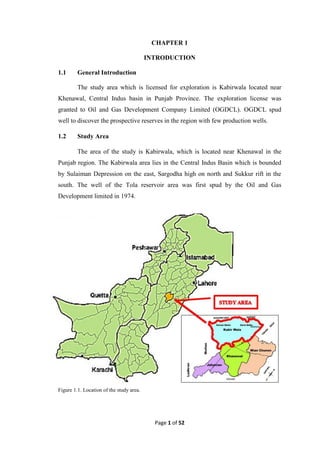
  • 1. Page 1 of 52 CHAPTER 1 INTRODUCTION 1.1 General Introduction The study area which is licensed for exploration is Kabirwala located near Khenawal, Central Indus basin in Punjab Province. The exploration license was granted to Oil and Gas Development Company Limited (OGDCL). OGDCL spud well to discover the prospective reserves in the region with few production wells. 1.2 Study Area The area of the study is Kabirwala, which is located near Khenawal in the Punjab region. The Kabirwala area lies in the Central Indus Basin which is bounded by Sulaiman Depression on the east, Sargodha high on north and Sukkur rift in the south. The well of the Tola reservoir area was first spud by the Oil and Gas Development limited in 1974. Figure 1.1. Location of the study area.
  • 2. Page 2 of 52 1.3 Geological and Geophysical Data Used The data for the research was obtained from the Land Mark Resources (LMKR) as requested by Bahria University to Directorate General of Petroleum Concessions Government of Pakistan (DGPC). Following of the data is acquired: 1.3.1 Seismic Lines: Table: 1.1. Seismic lines provided for interpretation. S.No Line Name Line Type Line Orentation 1. 854-KBR-49 Strike Line N-S 2. 854-KBR-50 Dip Line W-E 3. 844-KBR-51 Dip Line W-E 4. 844-KBR-52 Dip Line W-E 1.3.2 Well: Table: 1.2. Well logs provided for the petro-physical analysis. S.No Well Well Logs 1. Tola-01 Gamma Ray Log Bulk Density Log Neutron Log Sonic Log Resistivity Log 1.4 Base Map The base map shows the orientation of the seismic lines, shot points and the well location on the seismic line. It shows the three of the strike lines and the other one of the dip line in the opposite orientation. The dip lines KBR-50, KBR-51 and KBR-52 have the shooting order starting from the West direction to the East direction
  • 3. Page 3 of 52 whereas the stike line KBR-49 has the shooting order in the north to south direction as mentioned in the above table 1.1. Below is the base map of the study area. Figure.1.2. Base map of seismic lines of Kabirwala area. 1.5 Objectives of the Study The main purposes of this discussion are as follows: a) Make integrated interpretation of the available geophysical and geologic data. b) Manipulate the acquired data into an image that can be used to infer the sub- surface structure through time and depth contours.
  • 4. Page 4 of 52 c) Identification of the structural trend of the area with the help of 3-D visualization. d) Identification of the prospect zones, if any and to analyze them by Petro physical Analysis. 1.6 Methodology The methodology involves the following steps: a) To study the tectonic settings and geology of the area. b) Preparation of base map for Tola 1974 seismic survey. c) Marking the reflectors on the seismic sections. d) Identifications of faults using the seismic sections. e) Solving velocity windows for the calculation of depth. f) Preparation of Time and Depth contour maps for the marked reflectors. g) Interpretation of well logs of Tola-01. h) Generation of graphs using the well log data. i) To formulate most suitable recommendations and conclusions for the study area.
  • 5. Page 5 of 52 CHAPTER 2 REGIONAL GEOLOGY AND STRATIGRAPHY OF THE STUDY AREA 2.1 Introduction As the area of research lies on the Indus basin. The Indus basin is further divided into three basins as upper, central and lower. The Tola area is located and affected by the tectonics of the central Indus basin. The central Indus basin is then further divided into three zones as we move from the east to west. The further divided zones are known as Punjab Platform, Sulaiman Depression and Sulaiman Fold belt. In the northern side, the Middle Indus Basin is separated from the upper Indus Basin by the Sargodha high and Pezu uplift (Kadri, 1997). The southern boundary of the middle Indus basin is connected with the sukkur rift, on the eastern side, the Indian shield plays its part and on the western side, the Indian plate boundary marks the side of the central Indus basin. As discussed earlier, the central Indus basin is divided into three zones known as following zones (Kadri, 1995). 1. Punjab Platform 2. Sulaiman Foredeep 3. Sulaiman Fold belt 2.2 Punjab Platform The Punjab platform is dedicated as the eastern side of the middle Indus basin where the outcrops of the sedimentary rocks are not present (Kadri, 1995). The Punjab platform is tectonically dipping beneath the Sulaiman Depression. As the distance from the Indian Eurasian plate collision from the Punjab platform is very far, therefore, the Punjab platform area is least affected by the tectonics of the Eocene age. The number of folds and other structures are very less found as compared to the upper of lower Indus basin. There are many wells, which are drilled on this platform and based on the drilling and the core analysis, the stratigraphic sequence and the sequence correlation is generated. Moreover, the most significant pinch outs in Pakistan are revealed.
  • 6. Page 6 of 52 Figure.2.1. Geologic map of Pakistan showing basins. 2.3 Sulaiman Foredeep It is also known as the Sulaiman depression because of the presence of the subsidence zone in this region. Along the southern rim of the Sulaiman Foredeep, there is an arcuate and a transverse orientation of the stratigraphy. Because of the collision, the depression is created in between and in this case, Sulaiman depression is known to be that. The anticlines are proved by the seismic data evidence to be buries and then transformed because of the flow of the Eocene shales (Kadri, 1995). 2.4 Sulaiman Fold belt A large number of anticline features are generated in the result of the collision of the Indian and Eurasian belt. All of these stratigraphic and geologic features are very disturbed. There are a number of clearly detachments and huge anticlines in the Sulaiman belt and Kirthar range along the eastern margins of the Sulaiman fold belt. As we move towards the northern side, the eastern sides of the Sulaiman Fold belt has the very huge but narrow anticlines, which are as long as tens of Kilometers having the broken limbs which, are dipping towards the other side showing a reverse fault with reverse dip separation. In addition, these special kinds of situation and the tectonic activity generate the flower structure. The flower structure are the result of
  • 7. Page 7 of 52 the wrench faulting of the large scale and generating the crude oil reservoirs like Ranikot formation of the Paleocene age, Pab formation, Sember formation and the Lower guru formation aged as Cretaceous. During the collision of the Eurasian plate with the Indian plate, the basement rocks were categorized in three different zones. These zones or blocks of the basement rocks are categorized and differentiated by three different faults and also separates the central Indus basin. Out of these basement rocks and the basement blocks, the Kirthar basement faults, which separate the Sulaiman 18 from the Khuzdar, block. Similarly, the Jhelum basement fault separates the Indo-Pakistan plate main body and the Hazara block. In addition, Sulaiman basement fault separates the Hazara block and the Sulaiman block (Kadri, 1995). 2.5 Stratigraphy of Central Indus Basin Figure2.2. Generalized stratigraphic column of the central Indus Basin (modified after Kadri, 1995).
  • 8. Page 8 of 52 2.5.1 Miocene Age 2.5.1.1 Nagri Formation Nagri Formation: It consists of sandstone with subordinate clay and conglomerate. The upper contact with Dhok Pathan Formation is transitional. The age is Late Miocene. 2.5.1.2 Chinji Formation Chinji Formation: It consists of red clay with subordinate ash grey or brownish grey sandstone. It is only confined to the southern half of the eastern Sulaiman Range and is not developed in the rest of the Lower Indus Basin. In the Sulaiman Range it disconformably overlies the Nari Formation. It is conformably overlain by Nagri Formation. The age is Late Miocene. 2.5.2 Eocene Age 2.5.2.1 Ghazij Sui Member Ghazij sui member predominantly consists of shales that act as a regional rock in the area. The age is Eocene. 2.5.3 Paleocene Age 2.5.3.1 Dhungan Formaion The term Dungan limestone was introduced by Oldham (1890). Williams (1859) designated the type section to be near Harnai (lat. 300 08’ 38’’N; long. 670 59’ 33’’E) and renamed the unit Dungan Formation. It consists of limestone, shale and marl. The limestone is grey to buff, thin to medium bedded and conglomeratic. Shale is grey, khaki and calcareous. The marl is brown to grey, thin to medium bedded and fine grained. This formation is 50-400m maximum thick. Laterally this formational facies is more diverse, at places thick limestone deposits while at places minor limestone showings. The Sui main limestone is an upper part of Dungan limestone due to its variable behavior. It is thick in the Zinda Pir, Duki, Sanjawi, Harand, and also in Mughal Kot section but negligible as in Rakhi Gaj and Mekhtar areas. Petroleum showings are common in this formation especially in the Khatan area (Oldham 1890). Its lower contact with Bawata member of Rakhi Gaj Formation is conformable, however near the Axial Belt it has disconformity at the base, while the upper contact with Shaheed Ghat Formation is transitional and conformable. It has
  • 9. Page 9 of 52 many mega forams. It age is considered as Late Paleocene, rarely exceeding to early Eocene. However it is maintained all Paleocene in the Ziarat area and the Axial belt areas where the Sangiali and Rakhi Gaj formations i.e. the lower and middle Sangiali group is not developed. For example the Ziarat Laterite showing K-T boundary is contacted by Parh and Dungan formation (Malkani, 2010). 2.5.3.2 Ranikot Formation Ranikot formation is named after the Ranikot fortress in the Laki range near Sind. The Ranikot group is also known to be as the infra Nummulitic. The Ranikot group has been divided into three formation known as the lakhra (upper Ranikot), Bara (lower Ranikot) and Khadro formation. The lower part has the sandstone of brownish yellow color along with the shales and limestone. Similarly, the lower Ranikot has the variegated sandstone and shale and the grey to brown color limestone along with shale is present in the Lakhra formation. 2.5.4 Cretaceous Age 2.5.4.1 Lumshiwal Formation The Lumshiwal formation is being exposed in the salt range as a type locality. The Lumshiwal is covered across the Pakistan and has been named after the Lumshiwal nala. There has been a variation in the lithologies and the thickness in this formation all along. The Lumshiwal formation is being bedded as a thick one and the color exposed is grey along with the bedding with the sandstone with the considerable formations of sandy, glauconitic and silty shale towards the base. In the Lumshiwal formation, the sandstone present is feldspathic and has a considerable amount of carbon content. The age of the Lumshiwal formation in the area of the west side of Kohat is Aptian and near Nizampur and southern part of Hazara, the age is upper neocambrian to middle Albian. 2.5.4.2. Chichali Formation As we know that in this area, Chichali formation is acting like a source rock because of having shale in the formation. As the name implies, the Chichali is called after the Chichali pass. The color of the formation is usually dark green to grayish green and has sandy, silty and glauconitic shale in it. There are three members of the
  • 10. Page 10 of 52 Chichali shales, which includes the lower member having the sandy shale with phosphatic nodules. The in between member has the dark brown to green medium to fine grain calcareous sandstone while the upper member joins the Chichali pass. The contact of the Chichali formation with the Samana Suk formation lying beneath it is disconfirmable, while the contact with the Lumshiwal is gradational. 2.5.5. Jurassic Age 2.5.5.1. Samana Suk Formation Samana Suk formation has the limestone of the Jurassic age. It is the formation of the Surghar group along with the Lumshiwal, Datta, Shinawari and Chichali. The Samana Suk formation limestone has the very fine-grained limestone along with the clay and sand. The formation reflects its environment of deposition as the shallow marine or near coastal side. The lower contact of the Samana Suk formation is with the Shinawari formation having the sand and a disconfirmable contact with Chichali having shales mixed with sands. 2.5.5.2 Datta Formation Datta formation comprises of sandstone, shales, siltstone and mudstone. Age is Jurrasic. Datta shales act as good source rock whereas sandstones act as good reservoir rock. 2.5.6 Triassic Age 2.5.6.1 Kingriali Formation It consists of thin to thick bedded, massive, fine to coarse textured light grey brown dolomite and dolomitic limestone with interbeds of shale and marl in the upper part.The lower contact with Tredian Formation is transitional which is marked by interbedding of sandstone and dolomite. The upper contact with the Datta Formation is disconformable. The age is Late Triassic. 2.5.7 Permian Age 2.5.7.1 Amb Formation This formation consists of sandstone, limestone and shale. The sandstone beds occupy the lower part of formation. Upwards the sequence limestone with some shale appears. The upper contact with Wargal Limestone is conformable.
  • 11. Page 11 of 52 2.5.7.1 Warcha Formation The formation consists of medium to coarse grained sandstone, conglomeratic in places and interbeds of shale. The sandstone is cross bedded and arkosic. The pebbles of the unit are mostly of granite of pink colour and of quartzite. It conformably overlies the Dandot Formation. It is overlain by the Sardhai Formation with the transitional contact. The age is Early Permian. 2.6 Borehole Stratigraphy Table.2.1. Bore hole stratigraphy of Tola -01. FORMATIONS FORMATION TOPS(m) THICKNESS Nagri 0 484.00 Chinji 484 453.83 Nammal 937.82 40.20 Ghazij Sui Member 978.06 102.40 Dunghan 1080.46 36.86 Ranikot 1117.32 19.69 Lumshiwal 1132.00 30.63 Chichali 1167.63 6.42 Samana suk 1174.05 119.27 Shinawari 1293.32 106.68 Datta 1400.00 20.00 Kingriali 1420.00 84.14 Tredian 1504.14 66.86 Amb 1571.00 113.20 Sardhai 1684.20 125.80 Warcha 1810.00 19.00
  • 12. Page 12 of 52 2.7 Petroleum system A petroleum play is “Group of geologically related scenarios having similar circumstances of source, reservoir and trap”(Kadri,1995). Within a basement, the occurrence of the play elements plays a significant role in hydrocarbon accumulation. The major petroleum play elements are: a) Source rock b) Reservoir rock c) Seal rock d) Trap e) Migration 2.7.1 Source rock The source rock in the Tola area is Datta Formation with major shale rock present. 2.7.2 Reservoir rock The reservoir rock is the Dhungan formation and Lower Ranikot formation of Paleocene age and Samana Suk formation of Middle Jurassic age. 2.7.3 Seal rock Ghazij Sui Member of Eocene age act as the seal rock for the Dhungan formation.
  • 13. Page 13 of 52 CHAPTER 3 SEISMIC DATA ACQUISITION AND PROCESSING Seismic investigation starts in the field with the acquisition of seismic data. Seismic survey is used in oil industry to get the picture of subsurface. In this method, elastic properties of the subsurface materials are measured that vary with depth due to change in lithology and pore fluids. The predominance of the Seismic method over other geophysical method is due to various factors, the most important of which are the high accuracy, high resolution and great penetration. Seismic surveys are of two types i.e. seismic reflection and seismic refraction data. A seismic source is a localized region within which the sudden bang produces energy that leads to a rapid stressing of the surrounding medium. The typical seismic source is an explosion. There is a wide variety of seismic sources, characterized by differing energy levels and frequency characteristics. Conversion of ground motion to an electrical signal requires a transducer. On land, devices used for this purposes are known as seismometers or geophones and hydrophones are used while surveying at sea. 3.1 Types of Seismic Methods There are two types of seismic methods: (a) Refraction Method. (b) Reflection Method. 3.1.1 Seismic Refraction Method The Seismic Refraction method is based on the study of the elastic waves refracted along the geological layers in which the velocity of propagation of elastic waves is greater than the overlying strata. In order to have Seismic Refraction, the travelling wave must reflect critically from the layers. The incident wave must strike at a critical angle on the interface (where angle of refraction is 90 degrees). Then it travels along the boundary of the interfaces and emerges where the angle ic = ir. In the figure we observe that the angle of refraction is 90 degrees for one particular ray. It is the critically refracted ray that
  • 14. Page 14 of 52 shows how the wave travels at speed V1 right along the top of the lower layer (After Kearey, 1988). 3.1.2 Seismic Reflection Method Seismic reflection data is used more frequently due to its wide application in the oil industry. Reflection refers to the seismic energy that returns from an interface of contrasting acoustic impedance, known as reflector. This energy is recorded at the surface by sensitive detectors which respond to the ground motion produced by the reflected energy in time from place to place, which is indicative of the shape of structural features and their locations in sub-surface. Therefore, reflection techniques are mainly used in oil industry to produce structural maps of such deep-seated configurations such as anticlines, faults and salt domes. 3.2 Seismic Data Acquisition In simple terms and for all of the exploration environments, the general principle is to send sound energy waves (using an energy source like dynamite or Vibroseis) into the Earth, where the different layers within the Earth's crust reflect back this energy. These reflected energy waves are recorded over a predetermined time period (called the record length) by using hydrophones in water and geophones on land. The reflected signals are output onto a storage medium, which is usually magnetic tape. The general principle is similar to recording voice data using a microphone onto a tape recorder for a set period of time. Once the data is recorded onto tape, it can then be processed using specialist software which will result in processed seismic profiles being produced. These profiles or data sets can then be interpreted for possible hydrocarbon reserves.
  • 15. Page 15 of 52 Figure 3.1. Basic layout of a seismic Data acquisition. 3.3 Acquisition surveying parameters The acquisition surveying parameters are achieved through ‘hit and trial’ method; once the parameters are defined the survey is conducted. Acquisition parameters used for given seismic data are:
  • 16. Page 16 of 52 Table 3.1. General information about seismic lines under study (adopted from seismic section). 3.3.1 Source Parameters During the seismic survey the data was recorded by using the following source parameters. Table 3.2. Source parameters for seismic lines under study (adopted from seismic sections).). Energy Source Vibroseis (Vibrating in line) Sweep Frequency 10-40Hz Sweep Length 10 sec Base of Vibroseis 120 meters Y.P. Interval 100 meters LINE NAME 854-KBR-49 854-KBR-50 844-KBR-51 844-KBR-52 Line Strike Dip Dip Dip Line Direction South East East East S.P 101-480 101-351 101-341 101-401 Data Recorded February 1985 January 1985 December 1984 January 1985 Fold 24 24 24 24 Datum 150m A.M.S.L 150m A.M.S.L 150m A.M.S.L 150m A.M.S.L
  • 17. Page 17 of 52 3.3.2 Recording Parameters The parameters that are designed for seismic survey for acquiring high resolution data. These parameters mainly depend upon the nature of survey, topography of the area etc. These parameters are then stated with each recorded line for further help in the processing of the line. Recording parameters used for this survey are as follow: Table 3.3. Recording parameters of the lines under study (adopted from seismic section). Recorded By OGDCL Instruments MDS-16 Tape Format SEG-C Record length 16 sec Notch filter Out Sample interval 4 msec Number of Data Traces 48 3.4 Seismic data processing Once seismic data has been acquired on field, the second step is the processing data. Processing is required to compensate for the imperfections of the seismic data acquisition and degradation of the seismic waves during propagation. Seismic data processing consists of applying a sequence of computer programs, each designed to achieve one step along the path from field tape to record section. It involves the enhancement of raw data to a form that is used for seismic interpretation. Data processing converts the information recorded in the field into a form that mostly facilitates geological interpretation (Al. Sadi, 1980). Seismic data processing strategies and results are strongly affected by field acquisition parameters. Additionally, surface conditions have a significant impact on the quality of data collected in the field. Seismic data processing strategies and results are strongly affected by the field acquisition parameters. The purpose of seismic processing is to manipulate the
  • 18. Page 18 of 52 acquired data into an image that can be used to infer the subsurface structure. Only minimal processing would be required if we had a perfect acquisition system. Seismic data processing involves a number of steps in enhancement of signal to noise ratio (Yilmaz, 2001) The sequence has been categorized as follows: (a) Data Reduction. (b) Geometric Corrections. (c) Data Analysis and Parameter Optimization. (d) Data Refinement. (e) Data Presentation. Figure: 3.2. Generalized processing flowchart.
  • 19. Page 19 of 52 CHAPTER 4 SIESMIC INTERPRETATION 4.1 Introduction Seismic interpretation includes several steps, which are taken to solve the seismic section regarding all the stratigraphic, structural, and sequences. In the Oil and Gas sector, the main purpose of the seismic analysis is to locate and observe the best spot for the location of the hydrocarbon trapped in a certain structure, resisting its flow. But in the case of the Kabirwala lines, the reflector are found to be basic straight, thus cannot making any perfect trap for the hydrocarbon migration and maturation. 4.2 Interpretation Steps The seismic steps, which are performed to make a stratigraphic and structural analysis in the Kabirwala seismic lines, are showed as following. The basic interpretation steps are based on the seismic well log data of the Tola-01 in the Kabirwala area and also by the four seismic lines and a base map which helps in further analysis. Moreover, as the steps are completed, we are concluded with the reflectors and its potential of producing, storing and stopping the flow of the hydrocarbon migration. The steps are given below. 4.2.1 Velocity Window Solving First of the step is to solve the velocity windows given on the top of the seismic lines. As shown in the base map, the Tola-01 well lies on the seismic line 844-KBR-51. Therefore, the velocity windows are solved fot the KBR-51 seismic section. On the velocity windows, one column is of the time in milliseconds and the other column is of the RMS velocity. The RMS velocity is then multiplied with the one-way travel time in milliseconds to give the depth by the formula S=VT. The one- way travel time is acquired by dividing the time by 2. This column gives the depth of each time during the recording of seismic waves travelling under the subsurface. 4.2.2 Time Depth Chart As the velocity windows are solved, these are further plotted on a graph paper with the depth on the horizontal axis against the time given in the velocity windows
  • 20. Page 20 of 52 on the vertical axis. The depth chart is then plotted on the graph paper with all the seven velocity windows. Figure 4.1.Time depth graph of KBR-51 4.2.3 Reflector Marking As shown before, the desired well is spud on the KBR-51 seismic line therefore, the well tops of the Tola-01 well will be used in order to locate the required reflectors on the seismic section. The well top data gives us the formation tops with the required depth. The Kelly bushing is thus subtracted from the formation depth to make the reflectors of the formations on a similar datum scale. As far as the well tops of the Tola-01 are concerned, the tops of the required formation, which are Dunghan, Samana Suk, Datta and Warcha are following: Table 4.1.Formation tops of the marked reflectors. Formation Depth(m) Dunghan Formation 1080.46m Samana Suk Formation 1174.05m Datta Formation 1400.00m Warcha Formation 1810.00m 0 2000 4000 6000 8000 10000 12000 14000 0 1000 2000 3000 4000 5000 6000 Time-Depth Graph Time-Depth Graph Time(msec) Depth(m)
  • 21. Page 21 of 52 Therefore, the desired depths noted from the well tops of the Tola-01 are located on the best-fit line curve created from the velocity windows calculations and the graph helps to find the time against the depth on the seismic section. On the time depth graph, the following are the time values of the required depth using the depth time chart. As we know that the values of the time depth are taken on the seismic line 845-KBR-43 therefore, the well is shown in the seismic line. Moreover, a line is drawn from the required shot point across the seismic traces towards the six second time vertically. And the values of the time are also located on the well line over the seismic line. The time picked on the seismic line was as follows. (1). Dunghan--------------------------------------1.24 sec (2). Samana Suk ---------------------------------1.31 sec (3). Datta------------------------------------------1.44 sec (4). Warcha…………………………………1.55 sec The traces on the specific time using the referred time scaling are therefore used to locate the time on the well spot. In addition, after four traces are marked, four of them are therefore spread using the common line joining the traces. The traces are observed watching it parallel to the paper orientation rather looking it from top. The horizons are marked on the seismic line. 4.2.4. Jump correlation When all the seismic traces are marked on the seismic section of the 844- KBR-51, the base map is then observed. On the base map, the orientation of the seismic lines on a single paper is shown. In addition, the points of crossing of the lines are shown very clearly. The base map of the Kabirwala seismic lines shows that the seismic line KBR-51 at short point no 210 crosses the seismic line KBR-49 at short point 350. Therefore, KBR-51 is folded along the shot point 210 throughout the seismic section and on the other hand seismic line KBR-49 is opened along and the folded seismic line KBR-51 is held against the shot point no. 350 of KBR-49. The time lines on the vertical axis are taken common and overlapped each other. The seismic traces on the KBR-51 are continued on the line KBR-49 and are therefore marked throughout the seismic section.
  • 22. Page 22 of 52 As the seismic line KBR-51 is parallel to the KBR-50 and KBR-52 therefore, jump correlation with each other is not possible and hence the seismic line KBR-49 which is the strike line is used to mark the horizons on KBR-50 and KBR-52. Hence, the horizons are marked on the 854-KBR-50 using the seismic line KBR-49 whose shot point no. 305 crosses the KBR-50 at the shot point no. 255. The folded KBR-49 seismic line helps to mark Dunghan, Samana Suk, Datta and Warcha on the KBR-50. Similarly using KBR-49, the shot point no. 390 on it coincides with the shot point no. 240 on the KBR-52. Therefore, by correlating, the seismic horizons are marked on the KBR-52. Hence, four seismic lines are marked with the horizons. Figure 4.2. Seismic sections marked horizons on 854-KBR 49
  • 23. Page 23 of 52 Figure 4.3. Seismic sections marked horizons on 854-KBR-50 Figure 4.4. Seismic sections marked horizons on 844-KBR-51.
  • 24. Page 24 of 52 Figure 4.5. Seismic sections marked horizons on 844-KBR-52. 4.2.5. Time picking After the horizon marking on the seismic sections, the other task to do it to mark the time on every shot point and the time is then noted down for every reflector as R1 for Dunghan, R2 for Samana Suk, R3 for Datta and R4 for Warcha. Moreover, the time is picked for each shot point on each seismic line of Kabirwala. The trend of the reflectors is noted to be very straight and linear; there is minor faulting or folded structure in the reflectors of Dunghan, Samana Suk, Datta and Warcha. The four reflectors, thus has the approximately same time overall the seismic section. 4.2.6. Time contour map Contour map is generally defined as the line showing the same parameter (depth, elevation) on a 2D map. Here, the contours are made with the help of the time values, which is the time of the wave to reflect back from a prominent dense reflector or strata due to the acoustic impedance contrast. For each reflector R1, R2, R3 and R4 the contours of the time are generated on a map, taking the values of the reflector time picking on a line. In case of our research, the
  • 25. Page 25 of 52 reflectors of our interest are the Dunghan, Samana Suk, Datta and Warcha and these are plotted on the contour section referring to the reflection time values of these reflectors. Following are the reflector contour maps of the 854-KBR-49, 854-KBR-50, 844-KBR-51 and 844-KBR-52. As shown are the time contour maps of the four main reflectors of the four different seismic sections on a single map. The reflection time is therefore plotted in order to give an idea about the structure and the time delay of the seismic wave response due to the depth and other deflecting measures in the path of the wave travel. Figure 4.6. Time contour map of top of Dunghan Formation. The time contour map of the Dunghan Formation shows a monocline structure dipping towards the east direction. The seismic lines also conveys that there is minor faulting in these
  • 26. Page 26 of 52 formations therefore, it implies that the Dunghan formation is gently dipping as a monocline structure of the Punjab Platform. The time increases from 0.89 to 1.17 sec. Figure 4.7. Time contour map of top of Samana Suk Formation. The time contour map of the Samana Suk Formation also implies towards the monocline structure dipping gently towards the east direction. The reflection time increases from 1.01 to 1.28 sec.
  • 27. Page 27 of 52 The time contour map of the Datta Formation also give the picture of the monocline structure as by the other two formations depicting the feature of the Punjab platform. The reflection time increases from 1.06 sec to 1.4 sec. Figure 4.8. Time contour map of Top of Datta Formation.
  • 28. Page 28 of 52 Figue 4.9. Time contour map of top of Warcha Formation. The time contour map of the Warcha Formation also implies towards the monocline structure dipping gently towards the east direction. The reflection time increases from 1.24 to 1.56 sec. 4.2.7. Depth contour map As shown in the following figures, the depth contour map is given which is generated with the help of the reflection time values of the seismic lines of the Kabirwala area including 854-KBR-49, 854-KBR-50, 845-KBR-51, and 845-KBR-52. The depth contours shows the structure of the area and gives the overall information about the depth and its range of the particular formation. There are four reflectors on the seismic section of our concern and interest, which are Dunghan Formation, Samana Suk Formation, Datta Formation and Warcha Formation. Figure 4.9. Time contour map of top of Warcha Formation.
  • 29. Page 29 of 52 As it can be seen in the figure that the reflectors were quite straight in the laterally and it is therefore confirmed by the contour maps. These are marked as the reflector number 1, 2, 3 and 4 on the seismic section and the depth contour graph is according to these reflectors. The depth contour maps show the same depth contour line for the single depth value. The depth contour can help in giving the idea about the 3 dimensional structure of the particular lithology showing its depth as a surface. Figure 4.10. Depth contour map of top of Dunghan Formation. In contrary to the time contour map, the depth contour map of the Dunghan formation gives the same scenario about the dipping monocline structure of the Punjab Platform area of the Figure 4.10. Depth contour map of top of Dunghan Formation.
  • 30. Page 30 of 52 central Indus basin. The depth values of the Dunghan Formation is dipping towards Eastwards and the depth values are decreasing from 1295 to 920 m. Figure 4.11. Depth contour map of top of Samana Suk Formation. The Depth contour map of the Samana Suk Formation shows the decreasing depth northwards from 1480m to 1080m. Figure 4.11. Depth contour map of top of Samana Suk Formation.
  • 31. Page 31 of 52 Figure 4.12. Depth contour map of top of Datta Formation. The depth contour map of the Datta Formation follows almost the same pattern as of the Samana Suk Formation. The depth values are decreased from the 1610m to 1160m. The irregular change in depth is noticed but the overall structure is a monocline structure of the Punjab Platform. Figure 4.12. Depth contour map of top of Datta Formation.
  • 32. Page 32 of 52 Figure 4.13. Depth contour map of top of Warcha Formation. The depth contour map of the Warcha Formation follows almost the same pattern as of the Datta Formation. The depth values are decreased from the 1880m to 1400m northwards. The irregular change in depth is noticed but the overall structure is a monocline structure of the Punjab Platform. 4.2.8. 3D depth surfaces The 3D depth surfaces are generated using the depth values by the help of Surfer software. The 3D view of the specific formation surface helps in understanding the monocline structure followed by in the Punjab Platform region towards northwards. Figure 4.13. Depth contour map of top of Warcha Formation
  • 33. Page 33 of 52 Depth (m) Figure 4.14. 3D depth surface of Dunghan Formation. Figure 4.15. 3D Depth Surface of Samana Suk Formation Depth (m)
  • 34. Page 34 of 52 Depth (m) Figure 4.16. 3D depth surface of the Datta Formation. Figure 4.17. 3D depth surface of the Warcha Formation. Depth (m)
  • 35. Page 35 of 52 CHAPTER 5 PETROPHYSICAL ANALYSIS & INTERPRETATION OF WELL LOGS 5.1 Well Log Analysis 5.1.1 Purpose of the study The objective and purpose of our petro-physical analysis is to determine different rock properties that exists within the zone of interest in reservoir horizons in order to depict pay zones present in reservoir horizons and to quantify the hydrocarbon saturation present in it via log techniques in Tola-1 well. The following steps are followed to achieve this objective. (a) Carrying out log interpretation to mark the suitable reservoir zones (pay zones). (b) Computation of reservoir rock characteristics using various wire line logs. (c) Interpretation of the measured parameters for the evaluation of the hydrocarbon potential of the study area. Figure 5.1. Complete Log interpretation work flow 5.2 Methodology The general methodology implemented for petro-physical analysis is given below: (a) Firstly, the formation tops of understudy reservoir horizons got marked on logs at their respective depths. Log Readings Marking of Reservoir zones Lithology Identification Calculation of Shale volume Calculation of Density porosity & Effective porosity Calculation of Water Resistivity Evaluation of Water Saturation (Sw) Evaluation of Hydrocarbon Saturation (Sh)
  • 36. Page 36 of 52 (b) Than zone of interest got marked based on marking of crossover between Neutron and density curves. (c) Gamma ray log is used in the identification of lithology. (d) Porosity measurements using Neutron log. (e) Bulk density measurements using density log. (f) Gamma ray log interpretation for the calculation of Shale volume and Effective porosity. (g) Calculation of Permeability and Bulk volume of water by using saturation of water and effective porosity (h) Analysis of Resistivity logs for calculation of formation water resistivity and hence for the calculation of Saturation of Water and Saturation of Hydrocarbons. 5.3 Raw Log Data The raw log data was obtained from LMKR. The data contained the raw log curves. Following logs got obtained. (a) Gamma Ray Log (b) Neutron Log (c) Density log (d) Resistivity Log 5.3.1 Gamma Ray Log A common and inexpensive measurement of the natural emission of gamma rays by a formation. Gamma ray logs are particularly helpful because shales and sandstones typically have different gamma ray signatures that can be correlated readily between wells. A log of the total natural radioactivity, measured in API units. The measurement can be made in both open hole and through casing. The depth of investigation is a few inches, so that the log normally measures the flushed zone. Shales and clays are responsible for most natural radioactivity, so the gamma ray log often is a good indicator of such rocks, giving high values of gamma rays, while shale free sand stones have low values of gamma ray, because of less concentration of radioactive materials in them. However, other rocks are also radioactive, notably some carbonates and feldspar-rich rocks.
  • 37. Page 37 of 52 5.3.2 Neutron Log Referring to a log of porosity based on the effect of the formation on fast neutrons emitted by a source. Hydrogen has by far the biggest effect in slowing down and capturing neutrons. Since hydrogen is found mainly in the pore fluids, the neutron porosity log responds principally to porosity. However, the matrix and the type of fluid also have an effect. The log is calibrated to read the correct porosity assuming that the pores are filled with fresh water and for a given matrix (limestone, sandstone or dolomite). 5.3.3 Density Log Density logging is a well logging tool that can provide a continuous record of a formation's bulk density along the length of a borehole. In geology, bulk density is a function of the density of the minerals forming a rock (i.e. matrix) and the fluid enclosed in the pore spaces. This is one of three well logging tools that are commonly used to calculate porosity. The density log measures the electron density of the formation via the backscatter of gamma rays, which is related to true bulk density. The neutron log attempts a measurement of formation porosity by using the interaction between neutrons emitted through tool and hydrogen within the formation (Neutron-Density suite). 5.3.4 Resistivity Suite A log of the resistivity of the formation, expressed in ohm-m. The resistivity can take a wide range of values, and, therefore, for convenience is usually presented on a logarithmic scale from, for example, 0.2 to 2000 ohm-m. The resistivity log is fundamental in formation evaluation because hydrocarbons do not conduct electricity while all formation waters do. Therefore a large difference exists between the resistivity of rocks filled with hydrocarbons and those filled with formation water. Clay minerals and a few other minerals, such as pyrite, also conduct electricity, and reduce the difference. 5.4 Zone of Interest First of all, we used Gamma Ray Log to mark the clean zones and then the log trends of Neutron and Density logs were identified at clean zones. Crossovers were found between Neutron and Density log curves. These crossovers were the indication of hydrocarbons in the selected zone. The presence of hydrocarbons was also confirmed by the resistivity curves. Hence we marked one zone of interest.
  • 38. Page 38 of 52 Table 5.1 Zones of interest. Zone Formation Formation top (ft) Formation bottom (ft) Total Thickness (ft) Zone 1 SAMANA SUK 3855 4240 385 Zone 2 DATTA 4595 4655 60 5.5 Lithological Identification Gamma Ray log is used to determine the lithology. According to them the lithologies were sandstones and shales majorly. 5.6 Determination of volume of shale (Vsh) Volume of shale was calculated with the help of GR log. First of all the maximum and minimum values of the GR curve are determined and then the GR readings at different intervals are taken in each zone marked. Then, with the help of this data, shale volume or gamma ray shale index (IGR) is determined at different depth intervals with the help of the following formula Volume of shale was calculated by using Gamma Ray log. The values of the log depicted that radioactive materials were not present in the clear zone which indicated that shale was not present in the clear zone. (Schlumberger, 1974): IGR = 퐆퐑퐋퐨퐠−퐆퐑퐌퐢퐧. 퐆퐑퐌퐚퐱.−퐆퐑퐌퐢퐧. Where,  GRlog = Log response in the zone of interest, API units  GRmin = Log response in the clean beds of minimum gamma ray deflection, in API units  GRmax = Log response in the shale beds of maximum gamma ray deflection, in API units
  • 39. Page 39 of 52 5.7 Total porosity Porosity is defined as the number of void spaces as compared to the total volume of rock. These spaces are formed in the rock either during its deposition which is called primary porosity or due to the dissolution of grains by water or fracturing in which case it is called secondary porosity. It is denoted by “ϕ” and is expressed in percentage. Porosity can be determined through different ways but we determined porosity through two ways (Schlumberger, 1974) Total or Average Porosity = (Density porosity + Neutron porosity) /2 5.8 Neutron porosity Referring to a log of porosity based on the effect of the formation on fast neutrons emitted by a source. Hydrogen has by far the biggest effect in slowing and capturing neutrons. Since hydrogen is found in pore fluids, the neutron porosity log responds principally to porosity. Neutron Porosity= Readings from Neutron log. 5.9 Density porosity If the density log is used alone porosity can be determined by using ; 흋D = 흆퐦 − 흆퐛 흆퐦−흆퐟  휌m= matrix density (g/cm3) constant 2.71  휌b= log reading (g/cm3)  휌f = density of mud filtrate (g/cm3) constant 1 Inaccuracies may occur when taking readings in evaporites or gas bearing formations. The lower density will predict porosity higher than the actual value. 5.10 Effective porosity Effective porosity is the sum of all interconnected pore spaces. Effective Porosity is determined by using following formula: Effective porosity = Total porosity * (1-Vsh) Where, Vsh= Volume of shale
  • 40. Page 40 of 52 5.11 Resistivity of water (Rw) Resistivity of water is the resistivity of an unknown mixture of water and chlorine in the pore spaces. It is the most sensitive parameter in the computation of water saturation. The resistivity of water is calculated by using several techniques. 5.12 Water saturation The amount of water present in the pore spaces is called saturation of water and is denoted by “Sw”. Water saturation is calculated with the help of Archie’s (1942) equation. (Sw)n = √( 퓪 훗퓶)×(RwRt) Where,  Sw= Saturation of Water  = Effective Porosity  퓂=2 Cementation exponent  a= 1 (Tortuosity factor)  n= 2 (Saturation exponent)  Rw= Formation water resistivity  Rt= Formation true resistivity 5.13 Hydrocarbon saturation The amount of oil or other hydrocarbons present in the pore spaces is called the hydrocarbon saturation and is denoted by “Sh”. The determination of saturation of hydrocarbon is very important because it will depict the reservoir potential to produce hydrocarbons. If the saturation of hydrocarbon is very high then the next step begins but if the saturation of hydrocarbon is very small or less then well is considered to be dry because less saturated reservoir will not compensate for the drilling expenditures of the company. Hydrocarbon saturation is determined by the following formula (Schlumberger, 1974): SH=1-Sw
  • 41. Page 41 of 52 Where,  SH= Saturation of Hydrocarbon  Sw= Saturation of Water 5.14 Bulk volume of water Bulk volume of water is calculated with formula: BVW = Sw×φE Where,  BVW = Bulk volume of water  φE = Effective porosity  Sw = Water Saturation 5.15 Permeability Permeability is determined by using following formula (Schlumberger, 1977): 푲풆=[ퟐퟓퟎ⨉(흋ퟑ푺풘⁄)]ퟐ Where,  퐾푒= Permeability  휑= Effective porosity  푆푤= Saturation of Water 5.16 Petrophysical Analysis of Reservoir Zones 5.16.1 Samana Suk Formation - Zone # 1 In the figure 5.2, volume of shale mostly varies from 40 to 80%. This percentage of volume of shale depicts that the lithology is partially clean and partially dirty and represents some presence of sandstone in Sandstone formation.
  • 42. Page 42 of 52 Figure 5.2. Correlation between depth and volume of shale in Samana Suk formation. In the figure 5.3, effective porosity varies between 3 to 15 % upto a depth of 4772m and then decreases till 4773m which shows that after 4772m, compaction starts which damages the interconnectivity of pores. 3800 3850 3900 3950 4000 4050 4100 4150 4200 4250 4300 0 20 40 60 80 100 Volume of Shale in % Zone 1 Depth (ft)
  • 43. Page 43 of 52 Figure 5.3 . Correlation between depth and effective porosity in Samana Suk formation. In the figure 5.4, the saturation of water continously changes with the depth and this variation is due to the fractures or compaction present in the formation. 3800 3850 3900 3950 4000 4050 4100 4150 4200 4250 4300 0 10 20 30 40 50 60 Zone 1 Depth (ft) Effective Porosity in %
  • 44. Page 44 of 52 Figure 5.4 . Correlation between depth and saturation of water in Samana Suk formation. By comparing the figures 5.4 and 5.5, we can clearly identify that these two graphs are inverted images of each other. This represents that with an increase in saturation of hydrocarbon, the saturation of water decreases and vice versa. 3800 3850 3900 3950 4000 4050 4100 4150 4200 4250 4300 65 70 75 80 85 Zone 1 Depth (ft) Saturation of Water
  • 45. Page 45 of 52 3800 3850 3900 3950 4000 4050 4100 4150 4200 4250 4300 0 10 20 30 40 Zone 1 Depth (ft) Saturation of Hydrocarbon Figure 5.5 . Correlation between depth and saturation of hydrocarbon in Samana Suk formation. 5.16.2 Datta Formation - Zone # 2 In the figure 5.6, volume of shale mostly varies between 0-85% which shows that lithology of the formation is partially clean and partially dirty and therefore indicates a reservoir zone.
  • 46. Page 46 of 52 4590 4600 4610 4620 4630 4640 4650 4660 0 20 40 60 80 100 120 Zone 2 Depth (ft) Volume of Shale in % Figure 5.6 . Correlation between depth and volume of shale in Datta Formation. In the figure 5.7 the effective porosity is almost minimum at all depths and ranges from 5-25%.
  • 47. Page 47 of 52 4590 4600 4610 4620 4630 4640 4650 4660 0 5 10 15 20 25 30 Zone 2 Effective Porosity in % Depth (Feets) Figure 5.7. Correlation between depth and effective porosity in Datta Formation. In the figure 5.8, the saturation of water almost lies between the range of 0-10%. This shows that this zone is less water saturated and more hydrocarbon saturated.
  • 48. Page 48 of 52 Figure 5.8. Correlation between depth and saturation of water in Datta Formation. By comparing the figures 5.8 and 5.9, we can clearly identify that these two graphs are inverted images of each other. this represents that with an increase in saturation of hydrocarbon, the saturation of water decreases and vice versa. 4590 4600 4610 4620 4630 4640 4650 4660 88 89 90 91 92 93 Zone 2 Depth (ft) Saturation of Water
  • 49. Page 49 of 52 4590 4600 4610 4620 4630 4640 4650 4660 0 2 4 6 8 10 12 Zone 2 Depth (Feets) Saturation of Hydrocarbon Figure 5.9 , Correlation between depth and saturation of hydrocarbon in Datta formation.
  • 50. Page 50 of 52 5.17 RESULTS Table 5.2. Average properties of Reservoir zones of Samana Suk and Datta formation Zones Volume of Shale (%) Effectively Porosity Saturation of Water Saturation of Hydrocarbon Zone 1 41.17% 18.14% 76.43% 23.67% Zone 2 56% 13.90% 90.96% 9.1%
  • 51. Page 51 of 52 CONCLUSIONS • The seismic data interpretation of the area delineate the presence of horst and graben structure in the research area. • The time sections confirms the formations are getting shallower in west direction and deeper in the east direction. • The mapping shows the structure is dipping in the east west direction. • The mapping of the fault boundaries shows they are dipping in the east and west direction. • The 3D structural analysis shows the whole structure is getting shallower in the west direction and deeper in the east direction. • On the basis of petrophysical analysis zone 1 has better hydrocarbon potential than zone 2
  • 52. Page 52 of 52 REFERENCES Kazmi, A.H., and Jan, M.Q., 1997. Geology and tectonic of Pakistan, Graphic publishers, Karachi, Pakistan. Yilmaz., 2001. Seismic data analysis and processing, Inversion and analysis of seismic data, Society of exploration geophysics, Tulsa. Coffen, J.A., 1984. Seismic Exploration Fundamental, Pennwell Publishing Company, Tulsa, Oklahoma, 74101. Dobrin, M.B. and Savit, C.H., 1988. Introduction to Geophysical Prospecting, McGrawhillinternation edition, geology series. Asquith, G., and D. Krygowski, 2004, Basic Well Log Analysis: AAPG Methods in Exploration 16, p.31-35 Gakkhar, R.A., (2012), “Source-rock Potential and Origin of Hydrocarbons in the Cretaceous and Jurassic Sediments of the Punjab Platform (Indus Basin) Pakistan”, Search and Discovery Article # 50572