

Recommended
More Related Content
What's hot
What's hot (20)
Viewers also liked
Similar to Stp defined
Similar to Stp defined (20)
Recently uploaded
Recently uploaded (20)
Stp defined
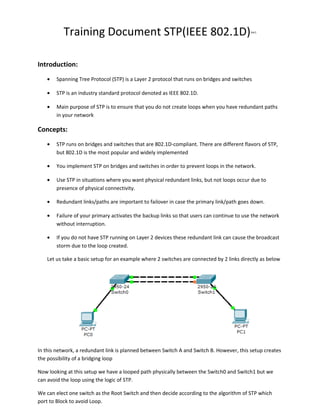
- 1. Training Document STP(IEEE 802.1D) Ver1 Introduction: • Spanning Tree Protocol (STP) is a Layer 2 protocol that runs on bridges and switches • STP is an industry standard protocol denoted as IEEE 802.1D. • Main purpose of STP is to ensure that you do not create loops when you have redundant paths in your network Concepts: • STP runs on bridges and switches that are 802.1D-compliant. There are different flavors of STP, but 802.1D is the most popular and widely implemented • You implement STP on bridges and switches in order to prevent loops in the network. • Use STP in situations where you want physical redundant links, but not loops occur due to presence of physical connectivity. • Redundant links/paths are important to failover in case the primary link/path goes down. • Failure of your primary activates the backup links so that users can continue to use the network without interruption. • If you do not have STP running on Layer 2 devices these redundant link can cause the broadcast storm due to the loop created. Let us take a basic setup for an example where 2 switches are connected by 2 links directly as below In this network, a redundant link is planned between Switch A and Switch B. However, this setup creates the possibility of a bridging loop Now looking at this setup we have a looped path physically between the Switch0 and Switch1 but we can avoid the loop using the logic of STP. We can elect one switch as the Root Switch and then decide according to the algorithm of STP which port to Block to avoid Loop.
- 2. Important Terminology: Root Bridge: It is switch with the best Bridge ID. It is the switch that has all ports working in the designated role. It will be the reference point from which the loop free topology is computed. All decisions such as which port will be forwarding or blocking are made from the perspective of the root bridge. Root bridge will be announcing its presence by sending BPDU frames. Other switches will relay those frames out their designated port given the hello time. Also, the root bridge has all its ports in the designated role (forwarding). BPDU(Bridge Protocol Data Unit): All switches communicate with one another using special frames called BPDU. Those frames contain multiple parameters that switches are going to process in order to create and maintain loop free topology Root Port: It is a port on a non-root switch, which is the shortest (the best) path towards the root bridge. Root bridge does NOT have any root ports. (no shortest path to itself ) Designated Ports: It is a port that is in the forwarding state. All ports of the root bridge are designated ports (they are never in a blocking state). BPDU frames our sent out this port. Spanning-tree port states: • Disabled - The port in this state does not participate in the STP operation (it is shut down) • Blocking - The port does NOT forward any Ethernet frames, does NOT accept any Ethernet frames (discards arriving frames), does NOT learn any MAC addresses. These ports DOES process BPDU frames received from a neighboring switch. If the port transitions to this state (blocking), it can stay blocked for 20 seconds by default (max_age). • Listening - The port in this state CAN send and receive the BPDU frames. However, the port in this state does NOT learn any MAC addresses, and does NOT forward or process incoming frames either. All Ethernet frames are being discarded. The computation of loop free topology takes place in this state. If the port transitions to this state (listening), it can stay in this state for 15 seconds by default (forward_delay). • Learning - The port in this state already knows its role (root port or designated port ) in the STP domain. However, the port will not forward any Ethernet frames yet. It will be learning MAC addresses from the frames arriving at the port in order to populate MAC address table. This helps avoid too much flooding when the port transition to the forwarding state. If the port transitions to this state (learning), it can stay in this state for 15 seconds by default (forward_delay). • Forwarding - The port in this state will forward all Ethernet frames as per switch operation. Also, the port will process all incoming Ethernet frames and will actively learn MAC addresses from the arriving traffic.
- 3. Working of STP: STP (IEEE 802.1d) Principles of Operation: STP majorly uses 3 basic rules to operate. • Single root bridge election. • Each non-root switch to select a single best port towards the root (root port). • Each non-root switch to select a single forwarding port per segment (designated port). Root Bridge Election: • Only one switch in the layer 2 network becomes the root bridge. • Root election is based on a single parameter that is found in the BPDU frame called: Bridge ID. The switch with the lowest Bridge ID becomes the root. Bridge ID = Priority + Base MAC Addess. Priority: The default value is: 32768. It is configurable parameter that is used to elect the root bridge. The lower the value is the more likely for a switch to become a root switch. Base Mac Address: It is the unique mac address every switch has been given by the manufacturer. It acts as the tie breaker when the priority is same. Lower the MAC address more likely it will be elected as the root switch. Example Topology:
- 4. Now if we take in consideration the above topology the first thing that will happen is election of root switch election. Step1: When the switches are turned ON each will send out the BPDUs considering self as the root switch and have the Root ID and the Bridge ID as the same. But once the election is complete all the not root switches will send the BPDUs with Root ID of the Root Switch’s ID and the Bridge ID as own ID. All the switches will receive the BPDUs and compare the its own Bridge IDs with the those of the others received by them by adjacent switches. The switch with the lowest Bridge ID will be selected as the Root Switch. In the above Example Switch 1 has the lowest Bridge ID as compared to all others hence is chosen as Root Switch. And all the ports are Designated Ports. Switch1#sh spann VLAN0001 Spanning tree enabled protocol ieee Root ID Priority 32769 Address 0009.7C2E.E864 This bridge is the root Hello Time 2 sec Max Age 20 sec Forward Delay 15 sec
- 5. Bridge ID Priority 32769 (priority 32768 sys-id-ext 1) Address 0009.7C2E.E864 Hello Time 2 sec Max Age 20 sec Forward Delay 15 sec Aging Time 20 Interface Role Sts Cost Prio.Nbr Type ---------------- ---- --- --------- -------- -------------------------------Fa0/1 Desg FWD 19 128.1 P2p Fa0/2 Desg FWD 19 128.2 P2p Step2: Now when we have the focal point of the topology figured out all non-root switches begin to calculate which port is the best (the least cost) towards the root bridge. Switch0 sees that Fa0/1 will be the best path to reach the Root Switch and marks it as Root Port. Similarly Switch2 sees that the best path to reach the root switch is Fa0/1 and will mark it as the Root Port. Switch0#sh spann VLAN0001 Spanning tree enabled protocol ieee Root ID Priority 32769 Address 0009.7C2E.E864 Cost 19 Port 1(FastEthernet0/1) Hello Time 2 sec Max Age 20 sec Forward Delay 15 sec Bridge ID Priority 32769 (priority 32768 sys-id-ext 1) Address 000C.CF5C.4BEA Hello Time 2 sec Max Age 20 sec Forward Delay 15 sec
- 6. Aging Time 20 Interface Role Sts Cost Prio.Nbr Type ---------------- ---- --- --------- -------- -------------------------------Fa0/1 Root FWD 19 128.1 P2p Fa0/2 Desg FWD 19 128.2 P2p Switch2#sh spann VLAN0001 Spanning tree enabled protocol ieee Root ID Priority 32769 Address 0009.7C2E.E864 Cost 19 Port 1(FastEthernet0/1) Hello Time 2 sec Max Age 20 sec Forward Delay 15 sec Bridge ID Priority 32769 (priority 32768 sys-id-ext 1) Address 0090.0CA4.E1B9 Hello Time 2 sec Max Age 20 sec Forward Delay 15 sec Aging Time 20 Interface Role Sts Cost Prio.Nbr Type ---------------- ---- --- --------- -------- -------------------------------Fa0/1 Root FWD 19 Fa0/2 Altn BLK 19 128.1 P2p 128.2 P2p Each speed has its arbitrarily assigned cost which is configurable. A few examples are below: 10 Mbps = 100 100 Mbps = 19 1 Gbps = 4
- 7. 10 Gbps = 2 Now if we go back and look at the Switch 0 and Switch 2 we will have 2 paths to reach the Root Switch. For Switch 0: Path1: Switch0(Fa0/1) >>>> (Fa0/1)Switch1 Path Cost = 19 Path2: Switch0(Fa0/2) >>>>(Fa0/2)Switch2(Fa0/1) >>>> (Fa0/2)Switch1 Path Cost = 19+19= 38 The lowest cost to reach the root becomes the root port. For Switch2: Path1: Switch2(Fa0/1) >>>> Fa(0/2)Switch1 Path Cost 19 Path2: Switch2(Fa0/2) >>> (Fa0/2) Switch0(Fa0/1) >>> (Fa0/1)Switch1 Path Cost 19+19=38 What if the Root Cost Path is identical? The following algorithm is used to determine the root port or designated port (in order): • Prefer the lowest Root Path Cost. • In case of the same Root Path Cost, prefer the lowest Bridge ID of the designated switch (the neighbor that sends BPDUs). • In case of receiving BPDUs on multiple ports from the same designated switch (BPDU sender), prefer the lowest Port ID (known also as port priority) of the sender. That parameter has a default value 128 and is configurable PortID: Port ID = priority + ID [Interface number]; the default port priority is 128 • In case of all above are did not resolve the problem, prefer the lowest Port ID on which the BPDU arrives. Step3: Designated Port Selection: This procedure follows exactly the same algorithm used for root port selection. Now on the link between Swith0 and Switch1 one port has to be designated ,now it again checks the above check list and sees that Switch0 has lower Bridge ID than Switch2. Thus making the Port Fa0/2 on Switch0 as the Designated port. Switch0#sh spann int fa0/2 Vlan Role Sts Cost Prio.Nbr Type ---------------- ---- --- --------- -------- -------------------------------VLAN0001 Desg FWD 19 128.2 P2p Switch0# Now the other end of this link becomes the Alternate Blocking port. Switch3#sh spannin int Fa0/2
- 8. Vlan Role Sts Cost Prio.Nbr Type ---------------- ---- --- --------- -------- -------------------------------VLAN0001 Altn BLK 19 128.2 P2p Now when the computation is finished we see that the loop free STP topology is formed and the green lights in the Picture shows the status of port is Forwarding and the RED lights indicates Blocking Status. Note: • • Priority of Switch can be reduced only in Multiples of 4096. We can forcefully made a switch as Root Switch by command Switch1(config)#spanning-tree vlan 1 root primary • You can also make the Root Switch as primary and secondary as well. Switch1(config)#spanning-tree vlan 1 root ? primary Configure this switch as primary root for this spanning tree secondary Configure switch as secondary root • If you want to check what is the base mac address on your switch type in: SW#show version | include Base