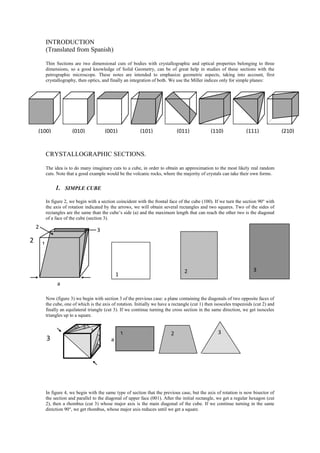
SlideShare a Scribd company logo
1 of 13
Download to read offline
INTRODUCTION
(Translated from Spanish)
Thin Sections are two dimensional cuts of bodies with crystallographic and optical properties belonging to three
dimensions, so a good knowledge of Solid Geometry, can be of great help in studies of these sections with the
petrographic microscope. These notes are intended to emphasize geometric aspects, taking into account, first
crystallography, then optics, and finally an integration of both. We use the Miller indices only for simple planes:
CRYSTALLOGRAPHIC SECTIONS.
The idea is to do many imaginary cuts to a cube, in order to obtain an approximation to the most likely real random
cuts. Note that a good example would be the volcanic rocks, where the majority of crystals can take their own forms.
1. SIMPLE CUBE
In figure 2, we begin with a section coincident with the frontal face of the cube (100). If we turn the section 90° with
the axis of rotation indicated by the arrows, we will obtain several rectangles and two squares. Two of the sides of
rectangles are the same than the cube’s side (a) and the maximum length that can reach the other two is the diagonal
of a face of the cube (section 3).
Now (figure 3) we begin with section 3 of the previous case: a plane containing the diagonals of two opposite faces of
the cube, one of which is the axis of rotation. Initially we have a rectangle (cut 1) then isosceles trapezoids (cut 2) and
finally an equilateral triangle (cut 3). If we continue turning the cross section in the same direction, we get isosceles
triangles up to a square.
In figure 4, we begin with the same type of section that the previous case, but the axis of rotation is now bisector of
the section and parallel to the diagonal of upper face (001). After the initial rectangle, we get a regular hexagon (cut
2), then a rhombus (cut 3) whose major axis is the main diagonal of the cube. If we continue turning in the same
direction 90°, we get rhombus, whose major axis reduces until we get a square.
(100) (010) (001) (101) (011) (110) (111) (210)
1
2
3
1
2 3
a
2
a
1 2
3
1 2 3
3
Now (Figure 5) we have the same initial section than before, but now we move the section in a parallel way. We get
several rectangles and a square section. It should be noted that the length of two sides of the rectangles, is the same
than the side of the cube.
The initial section in figure 6, is an equilateral triangle (the section of a tip of the cube), then we get isosceles
triangles, trapezoids (not shown) and finally we obtain a rectangle.
So far, we can see that most likely sections that we can obtain of random cuts of a cube are rectangles, triangles
and trapezoids. Less likely are hexagons, squares and rhombuses. The rectangles have two sides equal to the
side of the cube. The size of the sides of the triangles may vary from minuscule to the diagonal of one face of
the cube.
2. CUBE WITH INNER PLANES PARALLEL TO A FACE.
A set of equally spaced parallel planes, will show the smaller thickness and higher density (amount of traces per unit
area) in a perpendicular section. Cut 1 of figure 7 is perpendicular to x, y and z planes. Cut 2 is tilted and the traces of
the planes in this section are thicker and more spaced (less dense).
4
a 3
a
1 2 3
1
2
a
a
5
6
a
With this short introduction, let us consider a cube
than contains a set of planes parallel to one face
(figure 8).
Figure 9 shows the same type of cuts that figure 2. Section 1 is the frontal side of the cube (001) and does not cut
the inner planes. Section 2 cut only one plane with a weak slope. The trace of the plane in this section is then thick.
Amphibole of Sotará volcano, Colombia. Note the presence
of two cleavages, one thinner and denser and the other
thicker and less dense. If the objective (x40) is moved
slightly, the thinner cleavage does not seem to move, while
the other shows a neat movement. The thickness and dense
difference is due to section, almost perpendicular for the
thinner and tilted for the thicker one. One section
perpendicular to both cleavages, show them with the same
thickness and density. Plane polarized light. x10.
Thin cleavage
Thick cleavage
8
x y z
2
x y z
1
2
x y
z7
1
The other sections cut all the planes with increasing inclination, therefore the thickness of the traces decreases and
density increases.
Figure 10 shows the same cuts than figure 3, but the axis of rotation is now the diagonal of the top face of the cube
(001). In order to obtain the different sections it should be noted that in all cases, one of the edges of the sections is
contained in the frontal face of the cube (100) and then parallel to the inner planes. Therefore, the traces of these
planes in all sections will be parallel to this border line. Note also that the direction of rotation is toward the upper
face (001) which is perpendicular to the inner planes. Therefore, the thickness of traces decrease and their density
rise gradually.
2
3
4
5
1
9
1
2
3
4
5
3
10
1
2
1
2
3
3. CUBE WITH TWO INNER PLANES MUTUALLY PERPENDICULAR.
(Figure 11)
Figure 12 shows the same sections than figures 2 and 9. Note that cuts are perpendicular to X planes therefore their
traces have the minimum thickness and the maximum density in all them. For traces of Y planes is the same case than
figure 9. It should be noted that traces of both planes are perpendicular to each other, but for one family, their
thickness and density will vary.
11
y
3
x
1
x
2
3
y
4
1
2
3
4x y
12
Figure 13 shows exactly the same cut that section 3 of figure 10 or section 3 of figure 3. The cut is an equilateral
triangle, where one side is the diagonal of the front face (100) and then parallel to Y planes. Another side is the
diagonal of (010) face and then parallel to X planes. Therefore the traces of both planes in the section will have the
same thickness and density since the slope of cut is the same for both planes. Note that the angle between both traces
is 60º because is an equilateral triangle.
Note in figure 14 that vertical sides of cuts are parallel to both inner planes, therefore their traces will be parallel
each other. The thickness and density will depend of the slope of cut and will be the same only for section 3, but
note that the direction of inclination is opposite.
13
x
y
x
y
1
2 3
4
x y
1
y xy
2
3
y x
4
x
14
4. CUBE INSIDE ANOTHER CUBE.
Figure 15 shows a cube included in the center of another, twice its size.
Figure 16 shows three sections, the second one in
perspective for more clarity. It is clear, that the
probability that a random section cuts the inner cube,
will be low if the size is small, but if its size approach
the size of the external cube, more random sections
will contain both cubes.
We could see an analogy with all these figures and Thin Sections. Inner planes could be cleavage or twin planes. The
cube inside another one is similar to zoning of minerals or the external portion of a crystal altered by some chemical
reaction with his environment. It is important to note that although the thin sections are essentially two dimensional
bodies, their thickness (30 microns) is of great help in finding particular sections of a mineral. When the objective is
displaced slightly (40x would be appropriate), a cleavage or twin plane perpendicular to the thin section, will present
a fine trace and remain static in the field of view, but seems thicker and to move more or less insofar as the slop is
farther away of perpendicular to the thin section.
15
16
2
1 3
1 2
3
2
Plagioclases. Nevado del Ruiz. Colombia. Cross
polarized light. The left crystal shows the traces
of twin planes very thin and their density is high
suggesting that they are perpendicular to the
section. The right crystal instead, shows the twin
traces thicker and less dense. x4.
Plagioclase. Nevado del Ruiz volcano. Colombia. Left image plane
polarized light. Right image cross polarized light. Note both cleavages
almost mutually perpendicular and the trace of albite twin very thin.
These characteristics belong to a section very close to perpendicular to
a axis o [100]. The probability to find this section is very low but very
interesting, because it allows the better determination for composition
in routine methods of Thin Sections. x10.
OPTICS
Although these notes are not intended as a manual of Optical Mineralogy, always is useful to recall some basic
concepts that are handled in this discipline.
In anisotropic crystals, the speed of light can vary according to its direction of vibration. The refractive index is the
ratio between the speed of light in vacuum with respect to its velocity in the medium considered. The light used in
Petrography typically is orthoscopic and then is possible to associate directly a direction vibration of light with a
refractive index and in that way simplify the reasoning used in the determination of anisotropic sections.
If the refractive indices of a crystal are put all together in a point with the same direction in space that have the
vibration of light associated with each of them, the resulting envelope is an ellipsoid called the indicatrix. Depending
on the crystal symmetry this will be an ellipsoid of revolution (Tetragonal and Hexagonal systems) or not
(Orthorhombic, Monoclinic and Triclinic systems). It is useful to remember that the indicatrix is an artifact and by its
construction, its sections must necessarily pass through its center.
SECTIONS OF A REVOLUTION ELLIPSOID (17 and 18)
We take as the axis of rotation, the major axis of the ellipsoid but
rationing is essentially the same if we take the minor axis. A
perpendicular section to the major axis will be a circumference since
all points on the ellipse to rotate, describe a circle perpendicular to the
axis of rotation. A parallel section to major axis will be an ellipse with
the largest eccentricity can be obtained, that will decrease with the
angle of cut. Note that the minor axis is contained in all sections.
SECTIONS OF A ELLIPSOID NOT OF REVOLUTION
In this case the ellipsoid has three axes: large, medium
and small that are mutually perpendicular. Sections
perpendicular to one of these axes, contain the other
two. If we take the section that contains the major and
minor axis of the ellipsoid (figure 20), somewhere in
the ellipse, will give a distance to the center, equal to
the intermediate axis of the ellipsoid. If we continue
with the same procedure for cuts parallel to the axis of
the ellipsoid (Figure 21), we obtain a circular area
whose radius is the length of the intermediate axis of
the ellipsoid. These sections will be isotropic and its
perpendicular is called the optical axis. There will be
two circular sections is an ellipsoid not of revolution.
17
18
20
Np
Ng
Nm
19 great
petty
middle
There are several ways to symbolize the refractive indices. In
an effort to emphasize its size, is used here Ng (g great) for the
major axis of the ellipsoid (Figure 22), Np (p petty) for the
smaller one and Nm for the middle axis (these are equivalent
to the vibration directions Z, X and Y). In the case of an
anisotropic section, we will use n'p and n'g when we only
know the relative size between the two indices.
The birefringence of a mineral, is the difference between its major and minor refractive indices, that is, between
the major and minor axes of the indicatrix. The birefringence of a section is the difference between the major and
minor indices of the section. It is clear then that for a given mineral, the birefringence of the sections will range
from zero (the refractive indices of the section are equal, which corresponds to circular sections of the indicatrix) to
a maximum value that coincides with the nominal value given for the mineral (the section contains then the major
and minor axis of the indicatrix).
Usually the light used in the petrographic microscope is white and normal to the thin section (orthoscopic) being
polarized according to the direction of the Polarizer that is often taken NS; over the thin section, is the Analyzer
whose polarization direction is perpendicular or EW. Polarizer and Analyzer arranged in this way (crossed
polarizers) do not allow the passage of light. If we interpose between the two, another polarizer with its polarization
direction at 45 degrees of both, fwe see that there will be light transmission (Figure 23). This can be seen by vector
decomposition (Figure 24).
Clearly, if the direction of the intermediate polarizer coincides with either the Polarizer or Analyzer, no light is
transmitted.
Ng
Nm
1
1
Np
Nm
Ng
21
Circular
section
Ng
Np
Nm
22
Polarized
direction
23
Polarizer
Analyzer
The sections of the indicatrix, other than circular
sections, can be seen as a polarizer, with two
polarization directions mutually perpendicular. If any
of these directions coincides with the Polarizer of the
microscope, the beam of light coming from it, will
break down in the section into two beams with
mutually perpendicular vibration with different speeds
(different refractive indices).
If the analyzer is crossed, the two rays from the section are decomposed vectorially, interfering with each other,
resulting in a characteristic color (interference colours), which will depend on the birefringence of the section and
its thickness. These two factors together, constitute what is called the retardation. It is therefore important to
remember that the observed color (with crossed polarizers), depends not only on the birefringence of the section, but
also its thickness. Thus using the same thickness for the sections (typically 30 microns), the interference colours
varies only with the birefringence of the section.
In the event that one of the indices of the anisotropic section, match with the direction of the Polarizer (Figure 25) it
will exists only one direction of vibration in the section parallel to the Polarizer (the other index is 90 degrees to the
Polarizer and can not provide components). With crossed nicols, there is no light transmission (extinction position).
In order to observe the optical characteristics of one index of a section in natural light (without the Analizer) it must
be parallel to Polarizer. This is accomplished by taking the section to extinction (crossed nicols), and remove the
Analyzer. The relief and color observed, belong to the index parallel to Polarizer. It is important to note that for
different positions, relief and color will be intermediate between both indices.
REAL CASE
HYPERSTHENE
Orthorhombic system. Two good cleavages {210} that cut a axis at
half distance and b axis at unity, but a is almost twice b in length,
that means that they are almost perpendicular (88°). Np (X)= 1.712
light rose-brown. Nm(Y)=1.724 pale yellow-green. Ng(Z)=1.727
pale grey-green. Biaxial Negative (the minor index is the bisector
of optical axes). 2V between 50° - 60° (Tröger, 1971). With these
values we can see that the birefringence of Hypersthene (Ng-Np) is
0.015 that is, an interference color of orange first order for 30
microns.
Figure 26 is a schematic perspective view of hypersthene. The refractive indices coincide with crystallographic axes.
The section (001), that is perpendicular to c axis (Orthorhombic system) contains a and b axis and then Np and Nm
indices. The birefringence of this section (Nm-Np) is 0.012 yellow first order for 30 microns of thickness. The
Polarizer
Analyzer
Middle
PolarizerVibration
of light
de la luz
24
Polarizer
Anisotropic
Section25
10
0
(210)
(010)
Ng c
Np
b
Nm
a
Optical axis26
cleavages are perpendicular to section then their traces are very thin, perpendicular each other and stay static if the
objective (x40) is moved slightly. In plane polarized light, if the major index of the section (Nm) is parallel to
Polarizer, the color of section will be yellowish hue. If we rotate the section 90º (Np will be parallel to Polarizer), we
will see a pinkish hue. In crossed polarized light, the extinction will be symmetric with respect to traces of cleavages.
Section (100) is perpendicular to a axis and then contains b and c axis and therefore Np and Ng indices. The
birefringence is the same than the mineral (Ng – Np) 0.015 orange first order. The cleavages are at 45º to the
section and then is difficult to observe them. The section is pleochroic between a greenish hue (Ng parallel to the
polarizer) and pink (Np aligned with the polarizer).
The section (010) contains Ng and Nm indices. The birefringence will be (Ng – Nm) 0.003 dark gray. For the same
reason as above, it will be difficult to observe the cleavages. The colors of the indices are greenish, therefore the
pleochroism is not obvious. The section is perpendicular to bisector of optical axis and can therefore be seen the
interference figure well centered.
The probability to obtain strictly these three sections is very small. However the sections close to them show
similar characteristics.
A section (210) that is parallel to one of the cleavages (figure 28)
contains Ng index while the minor axis of the section, will be
between Np and Nm therefore the birefringence is between 0.003
and 0.015. We may consider a white hue of interference more or
less. The color in plane polarized light will be between a greenish
(Ng) and pinkish hue (n’p). We can see only one cleavage with a
trace very thin because is almost perpendicular to section.
In figure 29 we start with a (001) section. In the first case, the cuts are directed toward the face (100) and they
remain parallel to the b axis, therefore, all sections contain the Np index. The major index of the initial section is
Nm and Ng for the final one, then the major index of the section (n’g) will have a value between these two indices.
The interference colors will be between yellow and orange. The traces of cleavages will become thicker and the
angle between them gradually decreases. If the objective is moved slightly the traces will move to opposite sides,
because although the angle is the same, the direction of inclination is opposite. Extinctions remain symmetrical
with respect to cleavages.
In the second case, the cuts are directed toward the face (010), remaining parallel to the a axis. Note that the plane
formed by the optical axes and indices Ng and Np is perpendicular to all sections and then the cuts will contain the
index Nm of the mineral. The other index in the initial section is Np and in the final one is Ng, so it will be a section
where this index is Nm and the section is isothropic or cyclic and perpendicular to one of optical axes. This section is
not pleochroic. The birefringence decrease then progressively from the initial section, to zero (cyclic section), before
rising slightly to a final birefringence of 0.003 (face (010)). As in the previous case the traces of cleavages thicken
progressively, the angle between them diminishes and extinctions remain symmetrical.
Starting from the same previous cut (001) towards (210), it can be seen that in this case, the sections will be almost
perpendicular to one of the cleavages. The situation is similar to the cuts in Figure 12. The traces of cleavage
perpendicular to the sections, will be fine, keep the same density and remain static when slightly displace the
(001) section (100) section (010) section
Nm
Ng
Np
Ng
Nm
27
Np
Ng
n‘p
28
microscope objective. The traces of the other cleavage will thicken, its density will decrease and appear to move
more strongly as the tilt angle decreases, when slightly move the objective. Note that only the initial section contains
two of the indices of the mineral, while the final contains only one (Ng). Both indices of the other cuts will have
intermediate values. The sections of the indicatrix are not evident in this case, however, the major index of initial
section bisects the traces of cleavages, while in the final one, this index is parallel to the only visible cleavage. It
could be seen that the major index of sections will be progressively close to the fine cleavage and the extinctions are
not parallel which means that extinctions for these sections are neither straight nor symmetric.
Toward (100) Face
n‘g
n‘g
Np
Np
Toward (010) Face
Cyclic section
Np
(001) Section
(001)Nm
Nm
n‘g
Nm
Nm
29
Toward (210) Face
n‘g
n‘p
n‘g
n‘p
Hypersthene. Section close to (001) face.
The traces of two cleavages are thin and
almost perpendicular each other. Yellow first
order in crossed polarized light (30 microns).
Left, plane polarized light. Right, crossed
nicols. Andesite of Nevado del Ruiz
volcano.Colombia. x10.
EPILOGUE
From all these examples, it can be seen the importance of the Solid Geometry. A good knowledge of the ellipsoids,
together with the crystalline forms, will allow more reliable identification of the crystals and a better understanding of
their textures. In short, a three-dimensional ‘vision’, can go beyond the simple identification of minerals and is a
necessary starting point in structural studies.
BIBLIOGRAPHY
SHELLEY, David. Manual of Optical Mineralogy. 1975. Elsevier.
STOIBER, Richard; MORSE, Stearns. Crystal identification with the polarizing microscope. 1994. Chapman & Hall.
TRÖGER, W.E.. Optische Bestimmung der gesteinsbildenden Minerale. 1971.
Hypersthene. Section close to (010) face.
Cleavages are no visible. Pleochroism is clear
and interference colors are grayish. The
section shows the interference figure well
centered.
Hypersthene. Section close to (100) face. This
section does not show cleavages, as they are far
from perpendicular to section. Pleochroism very
clear between greenish and pinkish colors. In
crossed polarized light, the interference color is
orange of first order (30 microns) and is the same
that the mineral (contains the major and minor
indices of mineral).

More Related Content

What's hot

10.01.03.005
10.01.03.00510.01.03.005
10.01.03.005badhanxy
 
Moment of inertia of plane figures
Moment of inertia of plane figuresMoment of inertia of plane figures
Moment of inertia of plane figuresAurobindaSthitapragn
 
R05010105 A P P L I E D M E C H A N I C S
R05010105  A P P L I E D  M E C H A N I C SR05010105  A P P L I E D  M E C H A N I C S
R05010105 A P P L I E D M E C H A N I C Sguestd436758
 
Properties of surfaces-Centre of gravity and Moment of Inertia
Properties of surfaces-Centre of gravity and Moment of InertiaProperties of surfaces-Centre of gravity and Moment of Inertia
Properties of surfaces-Centre of gravity and Moment of InertiaJISHNU V
 
Unit iii solid geometry
Unit iii  solid geometryUnit iii  solid geometry
Unit iii solid geometrymadhavimohite
 
Lesson 14 centroid of volume
Lesson 14 centroid of volumeLesson 14 centroid of volume
Lesson 14 centroid of volumeLawrence De Vera
 
Chapter 6: Pure Bending and Bending with Axial Forces
Chapter 6: Pure Bending and Bending with Axial ForcesChapter 6: Pure Bending and Bending with Axial Forces
Chapter 6: Pure Bending and Bending with Axial ForcesMonark Sutariya
 
centroid & moment of inertia
centroid & moment of inertiacentroid & moment of inertia
centroid & moment of inertiasachin chaurasia
 
Mini project For M.tech Structural Engineering Deflection of Simply supported...
Mini project For M.tech Structural Engineering Deflection of Simply supported...Mini project For M.tech Structural Engineering Deflection of Simply supported...
Mini project For M.tech Structural Engineering Deflection of Simply supported...vaignan
 
Centroids and center of mass
Centroids and center of massCentroids and center of mass
Centroids and center of massIntishar Rahman
 
Unsymmetrical bending (2nd year)
Unsymmetrical bending (2nd year)Unsymmetrical bending (2nd year)
Unsymmetrical bending (2nd year)Alessandro Palmeri
 
Moment of inertia of non symmetric object
Moment of inertia of non symmetric objectMoment of inertia of non symmetric object
Moment of inertia of non symmetric objectIntishar Rahman
 
ESA Module 5 Part-B ME832. by Dr. Mohammed Imran
ESA Module 5 Part-B ME832. by Dr. Mohammed ImranESA Module 5 Part-B ME832. by Dr. Mohammed Imran
ESA Module 5 Part-B ME832. by Dr. Mohammed ImranMohammed Imran
 
6161103 10.9 mass moment of inertia
6161103 10.9 mass moment of inertia6161103 10.9 mass moment of inertia
6161103 10.9 mass moment of inertiaetcenterrbru
 
How to find moment of inertia of rigid bodies
How to find moment of inertia of rigid bodiesHow to find moment of inertia of rigid bodies
How to find moment of inertia of rigid bodiesAnaya Zafar
 

What's hot (18)

10.01.03.005
10.01.03.00510.01.03.005
10.01.03.005
 
Moment of inertia of plane figures
Moment of inertia of plane figuresMoment of inertia of plane figures
Moment of inertia of plane figures
 
R05010105 A P P L I E D M E C H A N I C S
R05010105  A P P L I E D  M E C H A N I C SR05010105  A P P L I E D  M E C H A N I C S
R05010105 A P P L I E D M E C H A N I C S
 
Properties of surfaces-Centre of gravity and Moment of Inertia
Properties of surfaces-Centre of gravity and Moment of InertiaProperties of surfaces-Centre of gravity and Moment of Inertia
Properties of surfaces-Centre of gravity and Moment of Inertia
 
Unit iii solid geometry
Unit iii  solid geometryUnit iii  solid geometry
Unit iii solid geometry
 
Lesson 14 centroid of volume
Lesson 14 centroid of volumeLesson 14 centroid of volume
Lesson 14 centroid of volume
 
CENTROID
CENTROIDCENTROID
CENTROID
 
Chapter 6: Pure Bending and Bending with Axial Forces
Chapter 6: Pure Bending and Bending with Axial ForcesChapter 6: Pure Bending and Bending with Axial Forces
Chapter 6: Pure Bending and Bending with Axial Forces
 
centroid & moment of inertia
centroid & moment of inertiacentroid & moment of inertia
centroid & moment of inertia
 
MOMENT OF INERTIA
MOMENT OF INERTIAMOMENT OF INERTIA
MOMENT OF INERTIA
 
Mini project For M.tech Structural Engineering Deflection of Simply supported...
Mini project For M.tech Structural Engineering Deflection of Simply supported...Mini project For M.tech Structural Engineering Deflection of Simply supported...
Mini project For M.tech Structural Engineering Deflection of Simply supported...
 
Centroids and center of mass
Centroids and center of massCentroids and center of mass
Centroids and center of mass
 
Unsymmetrical bending (2nd year)
Unsymmetrical bending (2nd year)Unsymmetrical bending (2nd year)
Unsymmetrical bending (2nd year)
 
Moment of inertia of non symmetric object
Moment of inertia of non symmetric objectMoment of inertia of non symmetric object
Moment of inertia of non symmetric object
 
ESA Module 5 Part-B ME832. by Dr. Mohammed Imran
ESA Module 5 Part-B ME832. by Dr. Mohammed ImranESA Module 5 Part-B ME832. by Dr. Mohammed Imran
ESA Module 5 Part-B ME832. by Dr. Mohammed Imran
 
6161103 10.9 mass moment of inertia
6161103 10.9 mass moment of inertia6161103 10.9 mass moment of inertia
6161103 10.9 mass moment of inertia
 
Mi2
Mi2Mi2
Mi2
 
How to find moment of inertia of rigid bodies
How to find moment of inertia of rigid bodiesHow to find moment of inertia of rigid bodies
How to find moment of inertia of rigid bodies
 

Similar to Petrographic notes

Similar to Petrographic notes (20)

Chapter 9 plane figures
Chapter 9 plane figuresChapter 9 plane figures
Chapter 9 plane figures
 
Symmetry In Soccer
Symmetry In SoccerSymmetry In Soccer
Symmetry In Soccer
 
Crystal Structure
Crystal StructureCrystal Structure
Crystal Structure
 
g.pdf
g.pdfg.pdf
g.pdf
 
Eg1 n
Eg1 nEg1 n
Eg1 n
 
from wikipedea
from wikipedeafrom wikipedea
from wikipedea
 
Modern Geometry Topics
Modern Geometry TopicsModern Geometry Topics
Modern Geometry Topics
 
Crystallography and X-ray diffraction (XRD) Likhith K
Crystallography and X-ray diffraction (XRD) Likhith KCrystallography and X-ray diffraction (XRD) Likhith K
Crystallography and X-ray diffraction (XRD) Likhith K
 
spherical triangles
spherical trianglesspherical triangles
spherical triangles
 
Graphs and Representation.pptx
Graphs and Representation.pptxGraphs and Representation.pptx
Graphs and Representation.pptx
 
Final Report
Final ReportFinal Report
Final Report
 
Kepler's Laws Lab
Kepler's Laws LabKepler's Laws Lab
Kepler's Laws Lab
 
Awesome kepler's laws lab
Awesome kepler's laws labAwesome kepler's laws lab
Awesome kepler's laws lab
 
ideas of mathematics -17tilings (final)
ideas of mathematics -17tilings (final)ideas of mathematics -17tilings (final)
ideas of mathematics -17tilings (final)
 
Miller indecies
Miller indeciesMiller indecies
Miller indecies
 
Bell 301 unit II
Bell 301 unit IIBell 301 unit II
Bell 301 unit II
 
Interferometers
InterferometersInterferometers
Interferometers
 
TRIANGLE CONGRUENCE, SSS, ASA, SAS and AAS
TRIANGLE CONGRUENCE, SSS, ASA, SAS and AASTRIANGLE CONGRUENCE, SSS, ASA, SAS and AAS
TRIANGLE CONGRUENCE, SSS, ASA, SAS and AAS
 
Logo paper
Logo paperLogo paper
Logo paper
 
Solid State sysem4 feb21
Solid State sysem4 feb21Solid State sysem4 feb21
Solid State sysem4 feb21
 

Recently uploaded

Shark introduction Morphology and its behaviour characteristics
Shark introduction Morphology and its behaviour characteristicsShark introduction Morphology and its behaviour characteristics
Shark introduction Morphology and its behaviour characteristicsArubSultan
 
Q-Factor HISPOL Quiz-6th April 2024, Quiz Club NITW
Q-Factor HISPOL Quiz-6th April 2024, Quiz Club NITWQ-Factor HISPOL Quiz-6th April 2024, Quiz Club NITW
Q-Factor HISPOL Quiz-6th April 2024, Quiz Club NITWQuiz Club NITW
 
BÀI TẬP BỔ TRỢ TIẾNG ANH 11 THEO ĐƠN VỊ BÀI HỌC - CẢ NĂM - CÓ FILE NGHE (GLOB...
BÀI TẬP BỔ TRỢ TIẾNG ANH 11 THEO ĐƠN VỊ BÀI HỌC - CẢ NĂM - CÓ FILE NGHE (GLOB...BÀI TẬP BỔ TRỢ TIẾNG ANH 11 THEO ĐƠN VỊ BÀI HỌC - CẢ NĂM - CÓ FILE NGHE (GLOB...
BÀI TẬP BỔ TRỢ TIẾNG ANH 11 THEO ĐƠN VỊ BÀI HỌC - CẢ NĂM - CÓ FILE NGHE (GLOB...Nguyen Thanh Tu Collection
 
31 ĐỀ THI THỬ VÀO LỚP 10 - TIẾNG ANH - FORM MỚI 2025 - 40 CÂU HỎI - BÙI VĂN V...
31 ĐỀ THI THỬ VÀO LỚP 10 - TIẾNG ANH - FORM MỚI 2025 - 40 CÂU HỎI - BÙI VĂN V...31 ĐỀ THI THỬ VÀO LỚP 10 - TIẾNG ANH - FORM MỚI 2025 - 40 CÂU HỎI - BÙI VĂN V...
31 ĐỀ THI THỬ VÀO LỚP 10 - TIẾNG ANH - FORM MỚI 2025 - 40 CÂU HỎI - BÙI VĂN V...Nguyen Thanh Tu Collection
 
Objectives n learning outcoms - MD 20240404.pptx
Objectives n learning outcoms - MD 20240404.pptxObjectives n learning outcoms - MD 20240404.pptx
Objectives n learning outcoms - MD 20240404.pptxMadhavi Dharankar
 
ICS 2208 Lecture Slide Notes for Topic 6
ICS 2208 Lecture Slide Notes for Topic 6ICS 2208 Lecture Slide Notes for Topic 6
ICS 2208 Lecture Slide Notes for Topic 6Vanessa Camilleri
 
Unraveling Hypertext_ Analyzing Postmodern Elements in Literature.pptx
Unraveling Hypertext_ Analyzing  Postmodern Elements in  Literature.pptxUnraveling Hypertext_ Analyzing  Postmodern Elements in  Literature.pptx
Unraveling Hypertext_ Analyzing Postmodern Elements in Literature.pptxDhatriParmar
 
Tree View Decoration Attribute in the Odoo 17
Tree View Decoration Attribute in the Odoo 17Tree View Decoration Attribute in the Odoo 17
Tree View Decoration Attribute in the Odoo 17Celine George
 
DBMSArchitecture_QueryProcessingandOptimization.pdf
DBMSArchitecture_QueryProcessingandOptimization.pdfDBMSArchitecture_QueryProcessingandOptimization.pdf
DBMSArchitecture_QueryProcessingandOptimization.pdfChristalin Nelson
 
Scientific Writing :Research Discourse
Scientific  Writing :Research  DiscourseScientific  Writing :Research  Discourse
Scientific Writing :Research DiscourseAnita GoswamiGiri
 
4.9.24 School Desegregation in Boston.pptx
4.9.24 School Desegregation in Boston.pptx4.9.24 School Desegregation in Boston.pptx
4.9.24 School Desegregation in Boston.pptxmary850239
 
4.9.24 Social Capital and Social Exclusion.pptx
4.9.24 Social Capital and Social Exclusion.pptx4.9.24 Social Capital and Social Exclusion.pptx
4.9.24 Social Capital and Social Exclusion.pptxmary850239
 
BIOCHEMISTRY-CARBOHYDRATE METABOLISM CHAPTER 2.pptx
BIOCHEMISTRY-CARBOHYDRATE METABOLISM CHAPTER 2.pptxBIOCHEMISTRY-CARBOHYDRATE METABOLISM CHAPTER 2.pptx
BIOCHEMISTRY-CARBOHYDRATE METABOLISM CHAPTER 2.pptxSayali Powar
 
Satirical Depths - A Study of Gabriel Okara's Poem - 'You Laughed and Laughed...
Satirical Depths - A Study of Gabriel Okara's Poem - 'You Laughed and Laughed...Satirical Depths - A Study of Gabriel Okara's Poem - 'You Laughed and Laughed...
Satirical Depths - A Study of Gabriel Okara's Poem - 'You Laughed and Laughed...HetalPathak10
 
Comparative Literature in India by Amiya dev.pptx
Comparative Literature in India by Amiya dev.pptxComparative Literature in India by Amiya dev.pptx
Comparative Literature in India by Amiya dev.pptxAvaniJani1
 

Recently uploaded (20)

Shark introduction Morphology and its behaviour characteristics
Shark introduction Morphology and its behaviour characteristicsShark introduction Morphology and its behaviour characteristics
Shark introduction Morphology and its behaviour characteristics
 
Introduction to Research ,Need for research, Need for design of Experiments, ...
Introduction to Research ,Need for research, Need for design of Experiments, ...Introduction to Research ,Need for research, Need for design of Experiments, ...
Introduction to Research ,Need for research, Need for design of Experiments, ...
 
Q-Factor HISPOL Quiz-6th April 2024, Quiz Club NITW
Q-Factor HISPOL Quiz-6th April 2024, Quiz Club NITWQ-Factor HISPOL Quiz-6th April 2024, Quiz Club NITW
Q-Factor HISPOL Quiz-6th April 2024, Quiz Club NITW
 
BÀI TẬP BỔ TRỢ TIẾNG ANH 11 THEO ĐƠN VỊ BÀI HỌC - CẢ NĂM - CÓ FILE NGHE (GLOB...
BÀI TẬP BỔ TRỢ TIẾNG ANH 11 THEO ĐƠN VỊ BÀI HỌC - CẢ NĂM - CÓ FILE NGHE (GLOB...BÀI TẬP BỔ TRỢ TIẾNG ANH 11 THEO ĐƠN VỊ BÀI HỌC - CẢ NĂM - CÓ FILE NGHE (GLOB...
BÀI TẬP BỔ TRỢ TIẾNG ANH 11 THEO ĐƠN VỊ BÀI HỌC - CẢ NĂM - CÓ FILE NGHE (GLOB...
 
31 ĐỀ THI THỬ VÀO LỚP 10 - TIẾNG ANH - FORM MỚI 2025 - 40 CÂU HỎI - BÙI VĂN V...
31 ĐỀ THI THỬ VÀO LỚP 10 - TIẾNG ANH - FORM MỚI 2025 - 40 CÂU HỎI - BÙI VĂN V...31 ĐỀ THI THỬ VÀO LỚP 10 - TIẾNG ANH - FORM MỚI 2025 - 40 CÂU HỎI - BÙI VĂN V...
31 ĐỀ THI THỬ VÀO LỚP 10 - TIẾNG ANH - FORM MỚI 2025 - 40 CÂU HỎI - BÙI VĂN V...
 
Objectives n learning outcoms - MD 20240404.pptx
Objectives n learning outcoms - MD 20240404.pptxObjectives n learning outcoms - MD 20240404.pptx
Objectives n learning outcoms - MD 20240404.pptx
 
ICS 2208 Lecture Slide Notes for Topic 6
ICS 2208 Lecture Slide Notes for Topic 6ICS 2208 Lecture Slide Notes for Topic 6
ICS 2208 Lecture Slide Notes for Topic 6
 
Unraveling Hypertext_ Analyzing Postmodern Elements in Literature.pptx
Unraveling Hypertext_ Analyzing  Postmodern Elements in  Literature.pptxUnraveling Hypertext_ Analyzing  Postmodern Elements in  Literature.pptx
Unraveling Hypertext_ Analyzing Postmodern Elements in Literature.pptx
 
Tree View Decoration Attribute in the Odoo 17
Tree View Decoration Attribute in the Odoo 17Tree View Decoration Attribute in the Odoo 17
Tree View Decoration Attribute in the Odoo 17
 
Plagiarism,forms,understand about plagiarism,avoid plagiarism,key significanc...
Plagiarism,forms,understand about plagiarism,avoid plagiarism,key significanc...Plagiarism,forms,understand about plagiarism,avoid plagiarism,key significanc...
Plagiarism,forms,understand about plagiarism,avoid plagiarism,key significanc...
 
Spearman's correlation,Formula,Advantages,
Spearman's correlation,Formula,Advantages,Spearman's correlation,Formula,Advantages,
Spearman's correlation,Formula,Advantages,
 
DBMSArchitecture_QueryProcessingandOptimization.pdf
DBMSArchitecture_QueryProcessingandOptimization.pdfDBMSArchitecture_QueryProcessingandOptimization.pdf
DBMSArchitecture_QueryProcessingandOptimization.pdf
 
Scientific Writing :Research Discourse
Scientific  Writing :Research  DiscourseScientific  Writing :Research  Discourse
Scientific Writing :Research Discourse
 
4.9.24 School Desegregation in Boston.pptx
4.9.24 School Desegregation in Boston.pptx4.9.24 School Desegregation in Boston.pptx
4.9.24 School Desegregation in Boston.pptx
 
4.9.24 Social Capital and Social Exclusion.pptx
4.9.24 Social Capital and Social Exclusion.pptx4.9.24 Social Capital and Social Exclusion.pptx
4.9.24 Social Capital and Social Exclusion.pptx
 
CARNAVAL COM MAGIA E EUFORIA _
CARNAVAL COM MAGIA E EUFORIA            _CARNAVAL COM MAGIA E EUFORIA            _
CARNAVAL COM MAGIA E EUFORIA _
 
BIOCHEMISTRY-CARBOHYDRATE METABOLISM CHAPTER 2.pptx
BIOCHEMISTRY-CARBOHYDRATE METABOLISM CHAPTER 2.pptxBIOCHEMISTRY-CARBOHYDRATE METABOLISM CHAPTER 2.pptx
BIOCHEMISTRY-CARBOHYDRATE METABOLISM CHAPTER 2.pptx
 
Faculty Profile prashantha K EEE dept Sri Sairam college of Engineering
Faculty Profile prashantha K EEE dept Sri Sairam college of EngineeringFaculty Profile prashantha K EEE dept Sri Sairam college of Engineering
Faculty Profile prashantha K EEE dept Sri Sairam college of Engineering
 
Satirical Depths - A Study of Gabriel Okara's Poem - 'You Laughed and Laughed...
Satirical Depths - A Study of Gabriel Okara's Poem - 'You Laughed and Laughed...Satirical Depths - A Study of Gabriel Okara's Poem - 'You Laughed and Laughed...
Satirical Depths - A Study of Gabriel Okara's Poem - 'You Laughed and Laughed...
 
Comparative Literature in India by Amiya dev.pptx
Comparative Literature in India by Amiya dev.pptxComparative Literature in India by Amiya dev.pptx
Comparative Literature in India by Amiya dev.pptx
 

Petrographic notes

  • 1. INTRODUCTION (Translated from Spanish) Thin Sections are two dimensional cuts of bodies with crystallographic and optical properties belonging to three dimensions, so a good knowledge of Solid Geometry, can be of great help in studies of these sections with the petrographic microscope. These notes are intended to emphasize geometric aspects, taking into account, first crystallography, then optics, and finally an integration of both. We use the Miller indices only for simple planes: CRYSTALLOGRAPHIC SECTIONS. The idea is to do many imaginary cuts to a cube, in order to obtain an approximation to the most likely real random cuts. Note that a good example would be the volcanic rocks, where the majority of crystals can take their own forms. 1. SIMPLE CUBE In figure 2, we begin with a section coincident with the frontal face of the cube (100). If we turn the section 90° with the axis of rotation indicated by the arrows, we will obtain several rectangles and two squares. Two of the sides of rectangles are the same than the cube’s side (a) and the maximum length that can reach the other two is the diagonal of a face of the cube (section 3). Now (figure 3) we begin with section 3 of the previous case: a plane containing the diagonals of two opposite faces of the cube, one of which is the axis of rotation. Initially we have a rectangle (cut 1) then isosceles trapezoids (cut 2) and finally an equilateral triangle (cut 3). If we continue turning the cross section in the same direction, we get isosceles triangles up to a square. In figure 4, we begin with the same type of section that the previous case, but the axis of rotation is now bisector of the section and parallel to the diagonal of upper face (001). After the initial rectangle, we get a regular hexagon (cut 2), then a rhombus (cut 3) whose major axis is the main diagonal of the cube. If we continue turning in the same direction 90°, we get rhombus, whose major axis reduces until we get a square. (100) (010) (001) (101) (011) (110) (111) (210) 1 2 3 1 2 3 a 2 a 1 2 3 1 2 3 3
  • 2. Now (Figure 5) we have the same initial section than before, but now we move the section in a parallel way. We get several rectangles and a square section. It should be noted that the length of two sides of the rectangles, is the same than the side of the cube. The initial section in figure 6, is an equilateral triangle (the section of a tip of the cube), then we get isosceles triangles, trapezoids (not shown) and finally we obtain a rectangle. So far, we can see that most likely sections that we can obtain of random cuts of a cube are rectangles, triangles and trapezoids. Less likely are hexagons, squares and rhombuses. The rectangles have two sides equal to the side of the cube. The size of the sides of the triangles may vary from minuscule to the diagonal of one face of the cube. 2. CUBE WITH INNER PLANES PARALLEL TO A FACE. A set of equally spaced parallel planes, will show the smaller thickness and higher density (amount of traces per unit area) in a perpendicular section. Cut 1 of figure 7 is perpendicular to x, y and z planes. Cut 2 is tilted and the traces of the planes in this section are thicker and more spaced (less dense). 4 a 3 a 1 2 3 1 2 a a 5 6 a
  • 3. With this short introduction, let us consider a cube than contains a set of planes parallel to one face (figure 8). Figure 9 shows the same type of cuts that figure 2. Section 1 is the frontal side of the cube (001) and does not cut the inner planes. Section 2 cut only one plane with a weak slope. The trace of the plane in this section is then thick. Amphibole of Sotará volcano, Colombia. Note the presence of two cleavages, one thinner and denser and the other thicker and less dense. If the objective (x40) is moved slightly, the thinner cleavage does not seem to move, while the other shows a neat movement. The thickness and dense difference is due to section, almost perpendicular for the thinner and tilted for the thicker one. One section perpendicular to both cleavages, show them with the same thickness and density. Plane polarized light. x10. Thin cleavage Thick cleavage 8 x y z 2 x y z 1 2 x y z7 1
  • 4. The other sections cut all the planes with increasing inclination, therefore the thickness of the traces decreases and density increases. Figure 10 shows the same cuts than figure 3, but the axis of rotation is now the diagonal of the top face of the cube (001). In order to obtain the different sections it should be noted that in all cases, one of the edges of the sections is contained in the frontal face of the cube (100) and then parallel to the inner planes. Therefore, the traces of these planes in all sections will be parallel to this border line. Note also that the direction of rotation is toward the upper face (001) which is perpendicular to the inner planes. Therefore, the thickness of traces decrease and their density rise gradually. 2 3 4 5 1 9 1 2 3 4 5 3 10 1 2 1 2 3
  • 5. 3. CUBE WITH TWO INNER PLANES MUTUALLY PERPENDICULAR. (Figure 11) Figure 12 shows the same sections than figures 2 and 9. Note that cuts are perpendicular to X planes therefore their traces have the minimum thickness and the maximum density in all them. For traces of Y planes is the same case than figure 9. It should be noted that traces of both planes are perpendicular to each other, but for one family, their thickness and density will vary. 11 y 3 x 1 x 2 3 y 4 1 2 3 4x y 12
  • 6. Figure 13 shows exactly the same cut that section 3 of figure 10 or section 3 of figure 3. The cut is an equilateral triangle, where one side is the diagonal of the front face (100) and then parallel to Y planes. Another side is the diagonal of (010) face and then parallel to X planes. Therefore the traces of both planes in the section will have the same thickness and density since the slope of cut is the same for both planes. Note that the angle between both traces is 60º because is an equilateral triangle. Note in figure 14 that vertical sides of cuts are parallel to both inner planes, therefore their traces will be parallel each other. The thickness and density will depend of the slope of cut and will be the same only for section 3, but note that the direction of inclination is opposite. 13 x y x y 1 2 3 4 x y 1 y xy 2 3 y x 4 x 14
  • 7. 4. CUBE INSIDE ANOTHER CUBE. Figure 15 shows a cube included in the center of another, twice its size. Figure 16 shows three sections, the second one in perspective for more clarity. It is clear, that the probability that a random section cuts the inner cube, will be low if the size is small, but if its size approach the size of the external cube, more random sections will contain both cubes. We could see an analogy with all these figures and Thin Sections. Inner planes could be cleavage or twin planes. The cube inside another one is similar to zoning of minerals or the external portion of a crystal altered by some chemical reaction with his environment. It is important to note that although the thin sections are essentially two dimensional bodies, their thickness (30 microns) is of great help in finding particular sections of a mineral. When the objective is displaced slightly (40x would be appropriate), a cleavage or twin plane perpendicular to the thin section, will present a fine trace and remain static in the field of view, but seems thicker and to move more or less insofar as the slop is farther away of perpendicular to the thin section. 15 16 2 1 3 1 2 3 2 Plagioclases. Nevado del Ruiz. Colombia. Cross polarized light. The left crystal shows the traces of twin planes very thin and their density is high suggesting that they are perpendicular to the section. The right crystal instead, shows the twin traces thicker and less dense. x4. Plagioclase. Nevado del Ruiz volcano. Colombia. Left image plane polarized light. Right image cross polarized light. Note both cleavages almost mutually perpendicular and the trace of albite twin very thin. These characteristics belong to a section very close to perpendicular to a axis o [100]. The probability to find this section is very low but very interesting, because it allows the better determination for composition in routine methods of Thin Sections. x10.
  • 8. OPTICS Although these notes are not intended as a manual of Optical Mineralogy, always is useful to recall some basic concepts that are handled in this discipline. In anisotropic crystals, the speed of light can vary according to its direction of vibration. The refractive index is the ratio between the speed of light in vacuum with respect to its velocity in the medium considered. The light used in Petrography typically is orthoscopic and then is possible to associate directly a direction vibration of light with a refractive index and in that way simplify the reasoning used in the determination of anisotropic sections. If the refractive indices of a crystal are put all together in a point with the same direction in space that have the vibration of light associated with each of them, the resulting envelope is an ellipsoid called the indicatrix. Depending on the crystal symmetry this will be an ellipsoid of revolution (Tetragonal and Hexagonal systems) or not (Orthorhombic, Monoclinic and Triclinic systems). It is useful to remember that the indicatrix is an artifact and by its construction, its sections must necessarily pass through its center. SECTIONS OF A REVOLUTION ELLIPSOID (17 and 18) We take as the axis of rotation, the major axis of the ellipsoid but rationing is essentially the same if we take the minor axis. A perpendicular section to the major axis will be a circumference since all points on the ellipse to rotate, describe a circle perpendicular to the axis of rotation. A parallel section to major axis will be an ellipse with the largest eccentricity can be obtained, that will decrease with the angle of cut. Note that the minor axis is contained in all sections. SECTIONS OF A ELLIPSOID NOT OF REVOLUTION In this case the ellipsoid has three axes: large, medium and small that are mutually perpendicular. Sections perpendicular to one of these axes, contain the other two. If we take the section that contains the major and minor axis of the ellipsoid (figure 20), somewhere in the ellipse, will give a distance to the center, equal to the intermediate axis of the ellipsoid. If we continue with the same procedure for cuts parallel to the axis of the ellipsoid (Figure 21), we obtain a circular area whose radius is the length of the intermediate axis of the ellipsoid. These sections will be isotropic and its perpendicular is called the optical axis. There will be two circular sections is an ellipsoid not of revolution. 17 18 20 Np Ng Nm 19 great petty middle
  • 9. There are several ways to symbolize the refractive indices. In an effort to emphasize its size, is used here Ng (g great) for the major axis of the ellipsoid (Figure 22), Np (p petty) for the smaller one and Nm for the middle axis (these are equivalent to the vibration directions Z, X and Y). In the case of an anisotropic section, we will use n'p and n'g when we only know the relative size between the two indices. The birefringence of a mineral, is the difference between its major and minor refractive indices, that is, between the major and minor axes of the indicatrix. The birefringence of a section is the difference between the major and minor indices of the section. It is clear then that for a given mineral, the birefringence of the sections will range from zero (the refractive indices of the section are equal, which corresponds to circular sections of the indicatrix) to a maximum value that coincides with the nominal value given for the mineral (the section contains then the major and minor axis of the indicatrix). Usually the light used in the petrographic microscope is white and normal to the thin section (orthoscopic) being polarized according to the direction of the Polarizer that is often taken NS; over the thin section, is the Analyzer whose polarization direction is perpendicular or EW. Polarizer and Analyzer arranged in this way (crossed polarizers) do not allow the passage of light. If we interpose between the two, another polarizer with its polarization direction at 45 degrees of both, fwe see that there will be light transmission (Figure 23). This can be seen by vector decomposition (Figure 24). Clearly, if the direction of the intermediate polarizer coincides with either the Polarizer or Analyzer, no light is transmitted. Ng Nm 1 1 Np Nm Ng 21 Circular section Ng Np Nm 22 Polarized direction 23 Polarizer Analyzer
  • 10. The sections of the indicatrix, other than circular sections, can be seen as a polarizer, with two polarization directions mutually perpendicular. If any of these directions coincides with the Polarizer of the microscope, the beam of light coming from it, will break down in the section into two beams with mutually perpendicular vibration with different speeds (different refractive indices). If the analyzer is crossed, the two rays from the section are decomposed vectorially, interfering with each other, resulting in a characteristic color (interference colours), which will depend on the birefringence of the section and its thickness. These two factors together, constitute what is called the retardation. It is therefore important to remember that the observed color (with crossed polarizers), depends not only on the birefringence of the section, but also its thickness. Thus using the same thickness for the sections (typically 30 microns), the interference colours varies only with the birefringence of the section. In the event that one of the indices of the anisotropic section, match with the direction of the Polarizer (Figure 25) it will exists only one direction of vibration in the section parallel to the Polarizer (the other index is 90 degrees to the Polarizer and can not provide components). With crossed nicols, there is no light transmission (extinction position). In order to observe the optical characteristics of one index of a section in natural light (without the Analizer) it must be parallel to Polarizer. This is accomplished by taking the section to extinction (crossed nicols), and remove the Analyzer. The relief and color observed, belong to the index parallel to Polarizer. It is important to note that for different positions, relief and color will be intermediate between both indices. REAL CASE HYPERSTHENE Orthorhombic system. Two good cleavages {210} that cut a axis at half distance and b axis at unity, but a is almost twice b in length, that means that they are almost perpendicular (88°). Np (X)= 1.712 light rose-brown. Nm(Y)=1.724 pale yellow-green. Ng(Z)=1.727 pale grey-green. Biaxial Negative (the minor index is the bisector of optical axes). 2V between 50° - 60° (Tröger, 1971). With these values we can see that the birefringence of Hypersthene (Ng-Np) is 0.015 that is, an interference color of orange first order for 30 microns. Figure 26 is a schematic perspective view of hypersthene. The refractive indices coincide with crystallographic axes. The section (001), that is perpendicular to c axis (Orthorhombic system) contains a and b axis and then Np and Nm indices. The birefringence of this section (Nm-Np) is 0.012 yellow first order for 30 microns of thickness. The Polarizer Analyzer Middle PolarizerVibration of light de la luz 24 Polarizer Anisotropic Section25 10 0 (210) (010) Ng c Np b Nm a Optical axis26
  • 11. cleavages are perpendicular to section then their traces are very thin, perpendicular each other and stay static if the objective (x40) is moved slightly. In plane polarized light, if the major index of the section (Nm) is parallel to Polarizer, the color of section will be yellowish hue. If we rotate the section 90º (Np will be parallel to Polarizer), we will see a pinkish hue. In crossed polarized light, the extinction will be symmetric with respect to traces of cleavages. Section (100) is perpendicular to a axis and then contains b and c axis and therefore Np and Ng indices. The birefringence is the same than the mineral (Ng – Np) 0.015 orange first order. The cleavages are at 45º to the section and then is difficult to observe them. The section is pleochroic between a greenish hue (Ng parallel to the polarizer) and pink (Np aligned with the polarizer). The section (010) contains Ng and Nm indices. The birefringence will be (Ng – Nm) 0.003 dark gray. For the same reason as above, it will be difficult to observe the cleavages. The colors of the indices are greenish, therefore the pleochroism is not obvious. The section is perpendicular to bisector of optical axis and can therefore be seen the interference figure well centered. The probability to obtain strictly these three sections is very small. However the sections close to them show similar characteristics. A section (210) that is parallel to one of the cleavages (figure 28) contains Ng index while the minor axis of the section, will be between Np and Nm therefore the birefringence is between 0.003 and 0.015. We may consider a white hue of interference more or less. The color in plane polarized light will be between a greenish (Ng) and pinkish hue (n’p). We can see only one cleavage with a trace very thin because is almost perpendicular to section. In figure 29 we start with a (001) section. In the first case, the cuts are directed toward the face (100) and they remain parallel to the b axis, therefore, all sections contain the Np index. The major index of the initial section is Nm and Ng for the final one, then the major index of the section (n’g) will have a value between these two indices. The interference colors will be between yellow and orange. The traces of cleavages will become thicker and the angle between them gradually decreases. If the objective is moved slightly the traces will move to opposite sides, because although the angle is the same, the direction of inclination is opposite. Extinctions remain symmetrical with respect to cleavages. In the second case, the cuts are directed toward the face (010), remaining parallel to the a axis. Note that the plane formed by the optical axes and indices Ng and Np is perpendicular to all sections and then the cuts will contain the index Nm of the mineral. The other index in the initial section is Np and in the final one is Ng, so it will be a section where this index is Nm and the section is isothropic or cyclic and perpendicular to one of optical axes. This section is not pleochroic. The birefringence decrease then progressively from the initial section, to zero (cyclic section), before rising slightly to a final birefringence of 0.003 (face (010)). As in the previous case the traces of cleavages thicken progressively, the angle between them diminishes and extinctions remain symmetrical. Starting from the same previous cut (001) towards (210), it can be seen that in this case, the sections will be almost perpendicular to one of the cleavages. The situation is similar to the cuts in Figure 12. The traces of cleavage perpendicular to the sections, will be fine, keep the same density and remain static when slightly displace the (001) section (100) section (010) section Nm Ng Np Ng Nm 27 Np Ng n‘p 28
  • 12. microscope objective. The traces of the other cleavage will thicken, its density will decrease and appear to move more strongly as the tilt angle decreases, when slightly move the objective. Note that only the initial section contains two of the indices of the mineral, while the final contains only one (Ng). Both indices of the other cuts will have intermediate values. The sections of the indicatrix are not evident in this case, however, the major index of initial section bisects the traces of cleavages, while in the final one, this index is parallel to the only visible cleavage. It could be seen that the major index of sections will be progressively close to the fine cleavage and the extinctions are not parallel which means that extinctions for these sections are neither straight nor symmetric. Toward (100) Face n‘g n‘g Np Np Toward (010) Face Cyclic section Np (001) Section (001)Nm Nm n‘g Nm Nm 29 Toward (210) Face n‘g n‘p n‘g n‘p Hypersthene. Section close to (001) face. The traces of two cleavages are thin and almost perpendicular each other. Yellow first order in crossed polarized light (30 microns). Left, plane polarized light. Right, crossed nicols. Andesite of Nevado del Ruiz volcano.Colombia. x10.
  • 13. EPILOGUE From all these examples, it can be seen the importance of the Solid Geometry. A good knowledge of the ellipsoids, together with the crystalline forms, will allow more reliable identification of the crystals and a better understanding of their textures. In short, a three-dimensional ‘vision’, can go beyond the simple identification of minerals and is a necessary starting point in structural studies. BIBLIOGRAPHY SHELLEY, David. Manual of Optical Mineralogy. 1975. Elsevier. STOIBER, Richard; MORSE, Stearns. Crystal identification with the polarizing microscope. 1994. Chapman & Hall. TRÖGER, W.E.. Optische Bestimmung der gesteinsbildenden Minerale. 1971. Hypersthene. Section close to (010) face. Cleavages are no visible. Pleochroism is clear and interference colors are grayish. The section shows the interference figure well centered. Hypersthene. Section close to (100) face. This section does not show cleavages, as they are far from perpendicular to section. Pleochroism very clear between greenish and pinkish colors. In crossed polarized light, the interference color is orange of first order (30 microns) and is the same that the mineral (contains the major and minor indices of mineral).