1. SIM900 demonstration projects
Introduction
SIM900 is a complete Quad-band GSM/GPRS module designed by SIMCom.
Featuring an industry-standard interface, the SIM900 delivers GSM/GPRS
850/900/1800/1900MHz performance for voice, SMS, Data and Fax in a small form
factor and with low power consumption.
SIM900 is designed as a DCE (Data Communication Equipment). It provides a
full modem serial port, which is used for data transmission and for sending AT
commands.
The SIM900 is integrated with the TCP/IP protocol; extended TCP/IP AT
commands are developed for customers to use the TCP/IP protocol easily, which is
very useful for those data transfer applications.
The following demonstration projects are developed based on SIM900 module:
1) Sending and receiving SMS,
2) Voice calls,
3) TCP/IP communication over GPRS.
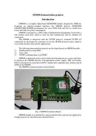
SIM900 evaluation board is used to make development process easier and faster.
It interfaces the SIM900 directly with appropriate power supply, SIM card holder,
RS232 serial port for connection with PC, handset port, earphone port, antenna and all
GPIO of the SIM900.
The SIM900 evaluation board is shown below:
Fig. 1 SIM900 Evaluation Board
SIM900 module is controlled by a microcontroller that contains user application.
Sample projects are described more detailed below.
2. Sending and receiving SMS
This example demonstrates I/O control by SMS messages. Proposed device has
1 digital input (switch) and 1 digital output (LED) that are monitored and controlled
by user via SMS messages.
Block diagram of the device is shown on figure 2.
Fig. 2 Block diagram of the device for SMS communication
Main tasks of this device are as follows:
1) Continuous monitoring of the digital input.
When transition of the input state occurs (OFF to ON or ON to OFF), the
corresponding SMS message is sent to the selected mobile phone.
For example, when input state changes from OFF to ON condition, the
following SMS message is sent to the selected mobile phone: “Input is ON”.
If input condition changes from ON to OFF, the “Input is OFF” SMS
message is sent to the selected mobile phone.
2) Control of the digital output (LED out).
User controls LED state by sending corresponding SMS.
When the device receives “Turn ON LED” SMS message, LED is turned
ON by microcontroller. The following response is returned to the mobile phone:
“LED is turned ON”.
If the device receives “Turn OFF LED” SMS message, LED is turned OFF
by microcontroller. The following response is returned to the mobile phone:
“LED is turned OFF”.
Other SMS messages that are received by this device are ignored. No
response is sent back in this case.
MCU program interfaces SIM900 module via UART. Dedicated AT commands
are used for processing of the SMS messages.
MCU SIM900UART
IN
OUT
Mobile
Antenna
3. Voice calls
This application allows to make and receive voice calls. Block diagram of the
device is depicted on figure 3.
Fig. 3 Block diagram of the device for voice calls
Microcontroller has only 2 inputs for buttons:
1) “Answer” or “Make a call”,
2) “Hang Up” or “Cancel the incoming call”.
These buttons are used to answer incoming calls and hang up. Main tasks of the
microcontroller are as follows:
1) Detection of buttons activities,
2) Sending appropriate AT commands to start and stop voice calls.
Other work is performed automatically by SIM900 module. This includes audio
signal processing and transfer.
The device can receive voice calls from any phone number.
Voice calls can be made to only one fixed mobile. This is done for
simplification purposes because no keypad is used.
MCU SIM900UART
IN
Mobile
Antenna
IN
“Answer”
“Hang Up”
MicrophoneSpeaker
4. TCP/IP communication over GPRS
The proposed project demonstrates TCP/IP communication over GPRS. It
allows to connect a SIM900 based device that is configured as client with a PC
application program that acts as server.
Block diagram of the TCP client and TCP server is shown on figure 4.
Fig. 4 Block diagram of the TCP client and server connection
Main tasks of the microcontroller are as follows:
1) Configuration of the SIM900 module for TCP/IP Client mode,
2) SIM900 control via AT commands for data transfer,
3) Updating of the LED state, when the corresponding command received from
server.
Extended TCP/IP AT commands are developed for customers to use the TCP/IP
protocol easily. MCU controls SIM900 module by corresponding AT commands.
Data transfer is performed by SIM900 module automatically.
When PC application is started, dedicated port number of server is opened. After
this moment server starts to listen for data from client.
Meanwhile, client (MCU with SIM900 module) tries to connect to the specified
TCP/IP server periodically. If the server is closed, connection with server is not
established. In this case the client tries to connect to the server again. This process
continues periodically until the server will not start listening to the client.
After the server starts to listen, the client establishes the connection with
selected server. When the client detects connection with the server, the following
message is sent to the server: “Client is ready”. After server receives this message, it
knows that client is ready for data reception.
There are several commands / messages that are responded by client in this
example project:
1) “Hi client.”
When client receives this message from server, it sends back the following
message to the server: “HELLO SERVER. What do you want?”
MCU
SIM900
TCP/IP Client
UART
OUT
Antenna
PC software
TCP/IP Server
5. 2) “Please, toggle LED.”
When client application receives this message, microcontroller toggles LED
state. If LED state becomes ON, the following message is returned to the server:
“LED is turned ON.”
If LED state changes to OFF, the following message is returned to the server:
“LED is turned OFF.”
For demonstration purposes the following software was used for TCP server
(http://www.hw-group.com/products/hercules/index_en.html):
Fig. 5 PC software for TCP server