WIND LOADING ON LIGHTING STEEL COLUMN - EN 40-3-1:2013
•
15 likes•17,705 views

WIND LOADING ON LIGHTING STEEL COLUMN - EN 40-3-1:2013

Recommended
Recommended
More Related Content
What's hot
What's hot (20)
Viewers also liked
Viewers also liked (20)
Similar to WIND LOADING ON LIGHTING STEEL COLUMN - EN 40-3-1:2013
Similar to WIND LOADING ON LIGHTING STEEL COLUMN - EN 40-3-1:2013 (20)
Recently uploaded
Recently uploaded (20)
WIND LOADING ON LIGHTING STEEL COLUMN - EN 40-3-1:2013
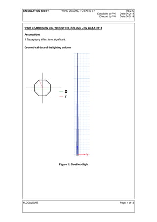
- 1. CALCULATION SHEET WIND LOADING TO EN 40-3-1 REV: C Calculated by:VN Date:04/2014 Checked by:VN Date:04/2014 WIND LOADING ON LIGHTING STEEL COLUMN - EN 40-3-1:2013 Assumptions 1. Topography effect is not significant. Geometrical data of the lighting column Figure 1: Steel floodlight FLOODLIGHT Page: 1 of 12
- 2. CALCULATION SHEET WIND LOADING TO EN 40-3-1 REV: C Calculated by:VN Date:04/2014 Checked by:VN Date:04/2014 Geometrical detail of steel column Height of the column: h 16.5m:= Thickness of section: t 6mm:= Length of each section: Ls 2m:= Section 1: D1.T 105mm:= Diameter at top: Diameter at bottom: D1.B 123mm:= Mean diameter: D1 D1.T D1.B+ 2 114 mm=:= Mean radius: R1 0.5 D1 57 mm=:= Section 2: D2.T 123mm:= Diameter at top: Diameter at bottom: D2.B 158mm:= Mean diameter: D2 D2.T D2.B+ 2 140.5 mm=:= Mean radius: R2 0.5 D2 70.25 mm=:= Section 3: Diameter at top: D3.T 140mm:= Diameter at bottom: D3.B 193mm:= Mean diameter: D3 D3.T D3.B+ 2 166.5 mm=:= Mean radius: R3 0.5 D3 83.25 mm=:= Section 4: Diameter at top: D4.T 175mm:= Diameter at bottom: D4.B 228mm:= Mean diameter: D4 D4.T D4.B+ 2 201.5 mm=:= Mean radius: R4 0.5 D4 100.75 mm=:= FLOODLIGHT Page: 2 of 12
- 3. CALCULATION SHEET WIND LOADING TO EN 40-3-1 REV: C Calculated by:VN Date:04/2014 Checked by:VN Date:04/2014 Section 5: Diameter at top: D5.T 210mm:= Diameter at bottom: D5.B 263mm:= Mean diameter: D5 D5.T D5.B+ 2 236.5 mm=:= Mean radius: R5 0.5 D5 118.25 mm=:= Section 6: Diameter at top: D6.T 245mm:= Diameter at bottom: D6.B 298mm:= Mean diameter: D6 D6.T D6.B+ 2 271.5 mm=:= Mean radius: R6 0.5 D6 135.75 mm=:= Section 7: Diameter at top: D7.T 290mm:= Diameter at bottom: D7.B 333mm:= Mean diameter: D7 D7.T D7.B+ 2 311.5 mm=:= Mean radius: R7 0.5 D7 155.75 mm=:= Section 8: Diameter at top: D8.T 313mm:= Diameter at bottom: D8.B 350mm:= Mean diameter: D8 D8.T D8.B+ 2 331.5 mm=:= Mean radius: R8 0.5 D8 165.75 mm=:= Material properties Modulus of elasticity: Es 210kN mm 2- := Loading Mass of structure: mass 200kg:= FLOODLIGHT Page: 3 of 12
- 4. CALCULATION SHEET WIND LOADING TO EN 40-3-1 REV: C Calculated by:VN Date:04/2014 Checked by:VN Date:04/2014 WIND PRESSURE (EN 40-3-1,cl.5.2) FOR SECTION 01 First foundamental period of steel pole (ETABS OUTPUT): T 0.6sec:= Factor dependent on the dynamic behavior of the column (EN 40-3-1,cl.5.2.4): 1.00240 0.00500 T s 4 - 0.05144 T s 3 + 0.22793 T s 2 - 0.67262 T s + 1.334=:= Factor related to topography (Topography effects in not significant) (EN 40-3-1,cl.5.2.5): f 1.0:= Figure 1: Isotach contours of the foundamental calue of he basic wind velocity Air density (EN 40-3-1,cl.5.2.2): 1.25kg m 3- := Altitude factor (EN 40-3-1,cl.5.2.2): CALT 1.0:= Basic value of the eference wind velocity at 10m above sea level (CYS EN 1991-1-4,NA 2.4 or cl.4.2) Vref.o 24m s 1- := Is the 10 minute mean wind velocity at 10 m above ground level for terrain category II (EN 40-3-1,cl.5.2.2): Vref CALT Vref.o 24 m s 1- =:= Factor to convert Vref from an annual probability of exceedence of 0.02 to other probabilities (EN 40-3-1,cl.5.2.2): Cs 0.92 0.959=:= FLOODLIGHT Page: 4 of 12
- 5. CALCULATION SHEET WIND LOADING TO EN 40-3-1 REV: C Calculated by:VN Date:04/2014 Checked by:VN Date:04/2014 Reference wind pressure (EN 40-3-1,Eq.2): q10 1 2 Cs( )2 Vref 2 331.2 N m 2- =:= WIND PRESSURE AND FORCE ON SECTION 1 OF STEEL COLUMN Exposure coefficient (for height m and terrain category II) (EN 40-3-1,cl.5.2.5): cez 2.66:= Height at section 01: h 16.0m:= Factor related to the column size (EN 40-3-1,cl.5.2.3): 1 0.01 h m - 0.84=:= Characteristic wind pressure: qz f cez q10 987.486 N m 2- =:= Shape coefficient for columns and brackets with regular octagonal cross-sections (EN 40-3-,Figure 3) Curve "Curve 1" R1 D1 0.075<if "Curve 2" R1 D1 0.075>if "Curve 2"=:= Wind speed (EN 40-3-1,cl.5.3): V 1 Cs qz 0.5 39.143 m s 1- =:= Kinematic viscosity of air at 20 oC (EN 40-3-1,cl.5.3): v 15.1 10 6- m 2 s 1- := Reynolds number (EN 40-3-1,cl.5.3): Re V D1 v 2.955 10 5 =:= Shape coefficient for colmns with octagonal cross section (EN 40-3-1,cl.5.3.2): c 1.25:= Horizontal force/meter (EN 40-3-1,Eq.3): Fc1 D1 c qz 0.141 kN m 1- =:= Horizontal force (EN 40-3-1,Eq.3): F1 D1 Ls c qz 281.433 N=:= WIND PRESSURE AND FORCE ON SECTION 2 OF STEEL COLUMN Exposure coefficient (for height m and terrain category II) (EN 40-3-1,cl.5.2.5): cez 2.57:= Height at section 01: h 14m:= Factor related to the column size (EN 40-3-1,cl.5.2.3): 1 0.01 h m - 0.86=:= Characteristic wind pressure: qz f cez q10 976.791 N m 2- =:= FLOODLIGHT Page: 5 of 12
- 6. CALCULATION SHEET WIND LOADING TO EN 40-3-1 REV: C Calculated by:VN Date:04/2014 Checked by:VN Date:04/2014 Shape coefficient for columns and brackets with regular octagonal cross-sections (EN 40-3-,Figure 3) Curve "Curve 1" R2 D2 0.075<if "Curve 2" R2 D2 0.075>if "Curve 2"=:= Wind speed (EN 40-3-1,cl.5.3): V 1 Cs qz 0.5 38.475 m s 1- =:= Kinematic viscosity of air at 20 oC (EN 40-3-1,cl.5.3): v 15.1 10 6- m 2 s 1- := Reynolds number (EN 40-3-1,cl.5.3): Re V D2 v 3.58 10 5 =:= Shape coefficient for colmns with octagonal cross section (EN 40-3-1,cl.5.3.2): c 1.24:= Horizontal force/meter (EN 40-3-1,Eq.3): Fc2 D2 c qz 0.17 kN m 1- =:= Horizontal force (EN 40-3-1,Eq.3): F2 D2 Ls c qz 340.353 N=:= WIND PRESSURE AND FORCE ON SECTION 3 OF STEEL COLUMN Exposure coefficient (for height m and terrain category II) (EN 40-3-1,cl.5.2.5): cez 2.47:= Height at section 01: h 12m:= Factor related to the column size (EN 40-3-1,cl.5.2.3): 1 0.01 h m - 0.88=:= Characteristic wind pressure: qz f cez q10 960.615 N m 2- =:= Shape coefficient for columns and brackets with regular octagonal cross-sections (EN 40-3-,Figure 3) Curve "Curve 1" R3 D3 0.075<if "Curve 2" R3 D3 0.075>if "Curve 2"=:= Wind speed (EN 40-3-1,cl.5.3): V 1 Cs qz 0.5 37.719 m s 1- =:= Kinematic viscosity of air at 20 oC (EN 40-3-1,cl.5.3): v 15.1 10 6- m 2 s 1- := FLOODLIGHT Page: 6 of 12
- 7. CALCULATION SHEET WIND LOADING TO EN 40-3-1 REV: C Calculated by:VN Date:04/2014 Checked by:VN Date:04/2014 Reynolds number (EN 40-3-1,cl.5.3): Re V D3 v 4.159 10 5 =:= Shape coefficient for colmns with octagonal cross section (EN 40-3-1,cl.5.3.2): c 1.21:= Horizontal force/meter (EN 40-3-1,Eq.3): Fc3 D3 c qz 0.194 kN m 1- =:= Horizontal force (EN 40-3-1,Eq.3): F3 D3 Ls c qz 387.061 N=:= WIND PRESSURE AND FORCE ON SECTION 4 OF STEEL COLUMN Exposure coefficient (for height m and terrain category II) (EN 40-3-1,cl.5.2.5): cez 2.35:= Height at section 01: h 10m:= Factor related to the column size (EN 40-3-1,cl.5.2.3): 1 0.01 h m - 0.9=:= Characteristic wind pressure: qz f cez q10 934.717 N m 2- =:= Shape coefficient for columns and brackets with regular octagonal cross-sections (EN 40-3-,Figure 3) Curve "Curve 1" R4 D4 0.075<if "Curve 2" R4 D4 0.075>if "Curve 2"=:= Wind speed (EN 40-3-1,cl.5.3): V 1 Cs qz 0.5 36.791 m s 1- =:= Kinematic viscosity of air at 20 oC (EN 40-3-1,cl.5.3): v 15.1 10 6- m 2 s 1- := Reynolds number (EN 40-3-1,cl.5.3): Re V D4 v 4.91 10 5 =:= Shape coefficient for colmns with octagonal cross section (EN 40-3-1,cl.5.3.2): c 1.18:= Horizontal force/meter (EN 40-3-1,Eq.3): Fc4 D4 c qz 0.222 kN m 1- =:= Horizontal force (EN 40-3-1,Eq.3): F4 D4 Ls c qz 444.495 N=:= FLOODLIGHT Page: 7 of 12
- 8. CALCULATION SHEET WIND LOADING TO EN 40-3-1 REV: C Calculated by:VN Date:04/2014 Checked by:VN Date:04/2014 WIND PRESSURE AND FORCE ON SECTION 5 OF STEEL COLUMN Exposure coefficient (for height m and terrain category II) (EN 40-3-1,cl.5.2.5): cez 2.21:= Height at section 01: h 8m:= Factor related to the column size (EN 40-3-1,cl.5.2.3): 1 0.01 h m - 0.92=:= Characteristic wind pressure: qz f cez q10 898.566 N m 2- =:= Shape coefficient for columns and brackets with regular octagonal cross-sections (EN 40-3-,Figure 3) Curve "Curve 1" R5 D5 0.075<if "Curve 2" R5 D5 0.075>if "Curve 2"=:= Wind speed (EN 40-3-1,cl.5.3): V 1 Cs qz 0.5 35.679 m s 1- =:= Kinematic viscosity of air at 20 oC (EN 40-3-1,cl.5.3): v 15.1 10 6- m 2 s 1- := Reynolds number (EN 40-3-1,cl.5.3): Re V D5 v 5.588 10 5 =:= Shape coefficient for colmns with octagonal cross section (EN 40-3-1,cl.5.3.2): c 1.15:= Horizontal force/meter (EN 40-3-1,Eq.3): Fc5 D5 c qz 0.244 kN m 1- =:= Horizontal force (EN 40-3-1,Eq.3): F5 D5 Ls c qz 488.775 N=:= WIND PRESSURE AND FORCE ON SECTION 6 OF STEEL COLUMN Exposure coefficient (for height m and terrain category II) (EN 40-3-1,cl.5.2.5): cez 2.04:= Height at section 01: h 6m:= Factor related to the column size (EN 40-3-1,cl.5.2.3): 1 0.01 h m - 0.94=:= Characteristic wind pressure: qz f cez q10 847.477 N m 2- =:= FLOODLIGHT Page: 8 of 12
- 9. CALCULATION SHEET WIND LOADING TO EN 40-3-1 REV: C Calculated by:VN Date:04/2014 Checked by:VN Date:04/2014 Shape coefficient for columns and brackets with regular octagonal cross-sections (EN 40-3-,Figure 3) Curve "Curve 1" R6 D6 0.075<if "Curve 2" R6 D6 0.075>if "Curve 2"=:= Wind speed (EN 40-3-1,cl.5.3): V 1 Cs qz 0.5 34.279 m s 1- =:= Kinematic viscosity of air at 20 oC (EN 40-3-1,cl.5.3): v 15.1 10 6- m 2 s 1- := Reynolds number (EN 40-3-1,cl.5.3): Re V D6 v 6.163 10 5 =:= Shape coefficient for colmns with octagonal cross section (EN 40-3-1,cl.5.3.2): c 1.13:= Horizontal force/meter (EN 40-3-1,Eq.3): Fc6 D6 c qz 0.26 kN m 1- =:= Horizontal force (EN 40-3-1,Eq.3): F6 D6 Ls c qz 520.003 N=:= WIND PRESSURE AND FORCE ON SECTION 7 OF STEEL COLUMN Exposure coefficient (for height m and terrain category II) (EN 40-3-1,cl.5.2.5): cez 1.8:= Height at section 01: h 4m:= Factor related to the column size (EN 40-3-1,cl.5.2.3): 1 0.01 h m - 0.96=:= Characteristic wind pressure: qz f cez q10 763.684 N m 2- =:= Shape coefficient for columns and brackets with regular octagonal cross-sections (EN 40-3-,Figure 3) Curve "Curve 1" R7 D7 0.075<if "Curve 2" R7 D7 0.075>if "Curve 2"=:= Wind speed (EN 40-3-1,cl.5.3): V 1 Cs qz 0.5 32.199 m s 1- =:= Kinematic viscosity of air at 20 oC (EN 40-3-1,cl.5.3): v 15.1 10 6- m 2 s 1- := Reynolds number (EN 40-3-1,cl.5.3): Re V D7 v 6.642 10 5 =:= FLOODLIGHT Page: 9 of 12
- 10. CALCULATION SHEET WIND LOADING TO EN 40-3-1 REV: C Calculated by:VN Date:04/2014 Checked by:VN Date:04/2014 Shape coefficient for colmns with octagonal cross section (EN 40-3-1,cl.5.3.2): c 1.11:= Horizontal force/meter (EN 40-3-1,Eq.3): Fc7 D7 c qz 0.264 kN m 1- =:= Horizontal force (EN 40-3-1,Eq.3): F7 D7 Ls c qz 528.11 N=:= WIND PRESSURE AND FORCE ON SECTION 8 OF STEEL COLUMN Exposure coefficient (for height m and terrain category II) (EN 40-3-1,cl.5.2.5): cez 1.8:= Height at section 01: h 2m:= Factor related to the column size (EN 40-3-1,cl.5.2.3): 1 0.01 h m - 0.98=:= Characteristic wind pressure: qz f cez q10 779.594 N m 2- =:= Shape coefficient for columns and brackets with regular octagonal cross-sections (EN 40-3-,Figure 3) Curve "Curve 1" R8 D8 0.075<if "Curve 2" R8 D8 0.075>if "Curve 2"=:= Wind speed (EN 40-3-1,cl.5.3): V 1 Cs qz 0.5 32.199 m s 1- =:= Kinematic viscosity of air at 20 oC (EN 40-3-1,cl.5.3): v 15.1 10 6- m 2 s 1- := Reynolds number (EN 40-3-1,cl.5.3): Re V D8 v 7.069 10 5 =:= Shape coefficient for colmns with octagonal cross section (EN 40-3-1,cl.5.3.2): c 1.10:= Horizontal force/meter (EN 40-3-1,Eq.3): Fc8 D8 c qz 0.284 kN m 1- =:= Horizontal force (EN 40-3-1,Eq.3): F8 D8 Ls c qz 568.558 N=:= FLOODLIGHT Page: 10 of 12
- 11. CALCULATION SHEET WIND LOADING TO EN 40-3-1 REV: C Calculated by:VN Date:04/2014 Checked by:VN Date:04/2014 SUMMARY OF WIND LOAD PER UNIT LENGTH PER SECTION ON YAND X AXIS Horizontal uniform force of section 1: Fc1 0.141 kN m 1- = Horizontal uniform force of section 2: Fc2 0.17 kN m 1- = Horizontal uniform force of section 3: Fc3 0.194 kN m 1- = Horizontal uniform force of section 4: Fc4 0.222 kN m 1- = Horizontal uniform force of section 5: Fc5 0.244 kN m 1- = Horizontal uniform force of section 6: Fc6 0.26 kN m 1- = Horizontal uniform force of section 7: Fc7 0.264 kN m 1- = Horizontal uniform force of section 8: Fc8 0.284 kN m 1- = FLOODLIGHT Page: 11 of 12
- 12. CALCULATION SHEET WIND LOADING TO EN 40-3-1 REV: C Calculated by:VN Date:04/2014 Checked by:VN Date:04/2014 SUMMARY OF WIND POINT LOAD PER SECTION ON YAND X AXIS Horizontal force of section 1: F1 0.281 kN= Horizontal force of section 2: F2 0.34 kN= Horizontal force of section 3: F3 0.387 kN= Horizontal force of section 4: F4 0.444 kN= Horizontal force of section 5: F5 0.489 kN= Horizontal force of section 6: F6 0.52 kN= Horizontal force of section 7: F7 0.528 kN= Horizontal force of section 8: F8 0.569 kN= FLOODLIGHT Page: 12 of 12