1. NEW PRODUCT NEWS
No.1220
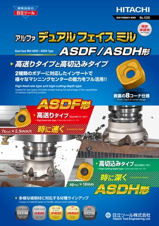
デュアル フェイス ミル
Dual-face Mill ASDF / ASDH Type
ASDF /ASDH形
高送りタイプと高切込みタイプ
2種類のボデーに対応したインサートで
様々なマシニングセンターの能力をフル活用 !
!
High-feed-rate type and high-cutting-depth type
Inserts for two types of bodies enable taking full advantage of the capabilities
of various machining centers.
8コーナ仕様
表裏の
ASDF 形
▶
▶
f z max = 2.5mm/t
高送りタイプ
Front / back 8-corner design
(切込み角10∼30°
)
High-feed-rate type (Cutting edge angle is 10 - 30°)
時に速く
Sometimes fast!
▶
▶
ap max = 10mm
▶
多様な被削材に対応する材種ラインアップ
高切込みタイプ
(切込み角60∼80°
)
High-cutting-depth type (Cutting edge angle is 60 - 80°)
時に深く
Sometimes deep!
ASDH 形
Lineup of material types to handle various work materials.
炭素鋼 合金鋼
・
炭素鋼 合金鋼
・
焼入れ鋼
30-50HRC
ステンレス鋼
鋳物
GX2140
JS4045
JP4020
JM4060
GX2120
Carbon steel
・
Alloy steel
Carbon steel
・
Alloy steel
Hardened
Steels
Stainless
Steels
Cast metal
2. デュアル フェイス ミル ASDF /ASDH形
■ インサート 形状 寸法 Insert Dimensions
・
耐久性に優れた大型インサート
1
Large inserts with excellent durability
●16サイズで厚さ7mmの大型インサートは破損トラブルを軽減します。
●
16-size 7mm-thick large insert reduces breakage problems.
ASDF形とASDH形で供用可能
2
ASDF type and ASDH type can be used together commonly applicable both to.
●1種のインサートで高送りと高切込みの2つのアプリケーションに対応可能です。
●工具管理の負担を軽減します。
One type of insert enables performing the two applications of high feed rate and
high cutting depth.
● Reduces tool management work.
●
経済性に優れたデュアルフェイス
3
Dual-face is highly economical.
●表裏で計8コーナの使用が可能です。
●
Top and bottom can be used for a total of 8 corners.
Fig.1 汎用形状
(C)
General-purpose shape
φ
W
T
P
M
K
H
炭素鋼 合金鋼
・
Carbon steel・
Alloy steel
SC SKD
ステンレス鋼
Stainless Steel
SUS
鋳鉄
Cast steel
高硬度材
安定切削
(平面連続切削)
切削状態
(目安)
Cutting conditions
(general criteria)
Stable cutting (plane continious cutting)
一般切削
(軽い断続切削)
Hardened steels
FC FCD
General cutting (light interrupted cutting)
不安定切削
(断続切削)
Unstable cutting (interrupred cutting)
JS-Coated
JSコート
JMコート
JP4020
JS4045
JM4060
GX2120
GX2140
M級
●
●
●
●
●
G級
●
●
●
●
●
Tolerance
Class
Item Code
JPコート
JP-Coated
精度
商品コード
SNMU1607EN-C
M class
SNGU1607EN-C
G class
GXコート
JM-Coated
寸法 Size(mm)
GX-Coated
内接円φW
形状
Shape
Inscribed Circle
厚みT
Thickness
φ16
7
Fig.1
●印:標準在庫品です。 ●:Stocked Items.
■ ボデーの使い分けマップ Body usage map
加工環境にあわせて選択可能な2種のボデーをラインアップ
軸方向切込み量 ap axial-depth of cut (mm)
Lineup of two types of bodies so you can select the appropriate one for your working environment.
ASDH 形
10
8
大きな切込み量で加工能率を改善する高切込みタイプ High-cutting-depth type for improved amounts
processing efficiency by cutting large
●鋳肌などの切込変動が大きい被削材 ● Work materials with large variations in cutting depth such
as cast surfaces, etc.
●テーブル送りが制限された環境
● Compatible with work environments where table feed rate is limited.
● If priority is on machined surface grade.
●加工面品位を優先する場合
ASDF 形
6
4
High-feed-rate type with large cutting amount per flute improves processing efficiency.
● Compatible with high-efficiency roughing that takes full advantage of machine capabilities.
● When priority is on durability for crushing cutting chips and interrupted cutting
2
0
大きな1刃送り量で加工能率を改善する高送りタイプ
●機械の最大能力を引き出す高能率荒加工
●切りくずの噛み込み、
断続切削に対する耐久性を優先する場合
0
0.5
1
1.5
2
一刃当りの送り量 fz (mm/t) Feed rate
2.5
2
3. Dual-face Mill ASDF / ASDH Type
■ インサート材種の特長 Features of insert material types
■ 被削材別推奨材種マップ Map of recommended material types by work material
不
定
加
工
被削材硬度
Low
高い
Work Hardness
低い
Unstable machining
安
High
加
工
Stable machining
定
Low
被削材硬度
高い
Work Hardness
High
低い
Low
被削材硬度
高い
Work Hardness
High
JS4045
JS4045
GX2140
安
低い
JM4060
JP4020
JP4020
JP4020
GX2120
一般構造用鋼 炭素鋼 合金鋼 炭素鋼 合金鋼 焼入れ鋼
・
・
焼入れ鋼
(200HB以下) (30HRC以下) (30∼45HRC)(45∼50HRC)
(50∼60HRC)
ステンレス鋼
SUS
鋳鉄
FC,FCD
Mild Steels
(200HB or less)
Stainless Steel
Cast Iron
鋼加工用材種
Carbon & Alloy Steels Carbon & Alloy Steels Hardened Steels
Pre-Harden Steels
(30HRC or less)
(30∼45HRC)
CVD Technology
Material type for processing steel
母材硬度
Base material hardness:89.2HRA
Hardened Steels
CVD Technology
GX2140
鋳鉄加工用材種
Material type for processing cast iron
母材硬度
■ 特 長 Features
Base material hardness:91.3HRA
GX2120
■ 特 長 Features
●強じん性K種超硬母材と厚膜CVDコーティングの組合せにより、
耐摩耗性と耐欠損性
の両立を実現。
●耐溶着性に優れる平滑α-AI2O3膜の採用により、
工具刃先の突発欠損を抑制。
●耐摩耗性に優れたK種系超硬母材と厚膜CVDコーティングの組合せにより、
最も耐摩
耗性に優れた材種。
・Combination of K-type carbide base material with excellent wear resistance and thick-membrane CVD
coating makes it an excellent material type with the highest wear resistance.
・Combination of high toughness K-type carbide base material and thick-membrane CVD coating
provides both high wear resistance and high chipping resistance.
・Smooth α-Al203 membrane with excellent welding resistance is used to suppress sudden chipping of tool flute tips.
■ 得意分野 Strong fields
■ 得意分野 Strong fields
●鋳鉄、
ダクタイル鋳鉄での乾式加工。
・Dry processing of cast iron and nodular cast iron.
●SS材、
SC材、
SCM材などの35HRC未満の工具鋼での乾式加工。
・Dry processing of tool steels of up to 35HRC such as SS type, SC type, SCM type, etc.
鋼加工用材種
PVD Technology
Material type for processing steel
母材硬度
Base material hardness:90.2HRA
PVD Technology
JS4045
JM4060
ステンレス鋼加工用材種
Material type for processing stainless steel
母材硬度
■ 特 長 Features
Base material hardness:89.2HRA
■ 特 長 Features
●汎用性に優れた超硬母材と耐酸化性に優れた新PVDコーティングとの組合せにより、
安定した工具寿命を実現。
●密着性を改善した新PVDコーティングと強じん性母材の組合せにより、
溶着に起因す
る突発損傷を改善。
・Combination of highly-versatile carbide base material and new PVD coating with excellent oxidation
・Combination of new PVD coating with improved adhesion and tough base material improves resistance
resistance provides stable tool life.
to sudden damage caused by welding.
■ 得意分野 Strong fields
■ 得意分野 Strong fields
●SS材、
SC材、
SCM材などの中∼強断続での加工。
●鋳鉄、
ダクタイル鋳鉄での中∼強断続での加工。
●ステンレス鋼加工。
・Processing of stainless steel.
・Intermediate to strong interrupted processing of SS material, SC material, SCM material, etc.
・Intermediate to strong interrupted processing of cast iron an nodular cast iron.
■ 材種マップ Grades map
PVD Technology
焼入れ鋼加工用材種
Material type for processing heat-treated steel
母材硬度
Base material hardness:91.3HRA
JP4020
◀耐欠損性
乾式推奨
Chipping resistance
Wear resistance▶
Dry processing recommended
GX2140
■ 特 長 Features
●被膜応力と組織を細かく制御する新技術により、
耐摩耗性と耐欠損性を向上。
耐摩耗性
GX2120
JS4045
・ New technology to tune finely stress and structure of membrane improves wear resistance and chipping
resistance.
■ 得意分野 Strong fields
乾式・湿式推奨
●40∼50HRCのプリハー
ドン鋼、
焼入れ鋼での加工。
Dry processing or wet processing recommended
JM4060
・Processing of prehardened steel and heat-treated steel with hardnesses of 40 to 50HRC.
3
JP4020
4. ASDF 形 【高送りタイプ】
■ ボデー 形状・寸法 Body Dimensions
(最大 fz = 2.5mm/t)
▶ 高送り加工
▶ 機械の最大能力を引き出す高能率
荒加工に対応
▶ High-feed-rate processing (Maximum f z=2.5mm/t)
▶ Compatible with high-efficiency roughing that takes full advantage of
machine capabilities.
θ
Fig.1(クーラント穴有)(With coolant hole)
切込み角 θ =10∼30°
最大軸方向切込み ap max=3.0mm
ap
Cutting Edge Angle θ =10∼30°
Maximum axial-direction cutting depth ap max=3.0mm
Fig.2(クーラント穴無)(Without coolant hole)
φDb
φd
a
Fig.3(クーラント穴無)(Without coolant hole)
φDb
φd
a
φDb
φd
a
b
b
b
R
R
R
Lf
Lf
ap
Lf
ap
ap
φd 1
φD c1
φD c2
φd 1
φDc1
φDc2
6.7
When using ASDF type for shaping processing
φ6
ASDF 形を形状加工で使用する場合
φd 1
φDc1
φDc2
プログラム上の刃先形状定義は下記を参照ください。
Refer to the following for the flute tip condition definitions for programming.
Bore type
ボアタイプ
φ1
※For slanted processing using ∅63 or ∅80, perform at 0.5° or less.
Do not perform using ∅100 or larger.
※When tool protrusion length is long (L /φDc2 ≧ 3), adjust ap .
削り残し量 Remains 1.33mm
商品コード
Type
φ20
※傾斜加工はφ63,φ80 で 0.5°
以下。 100 以上では行わないで下さい。
φ
は
※工具突出しが長い場合 L /φ c2 ≧ 3) ap を調整して下さい。
(
D
R6
タイプ
4
近似 R 定義 Approximate R definition = R 6
削り残し量 Remains 1.33mm
Item Code
在庫 刃数
ASDF5063R-4
内径インチ ASDF5080R-4
サイズ
ASDF5100R-5
Internal diameter
inch size
ASDF5125R-6
ASDF5160R-8
ASDF5063RM-4
内径ミリ ASDF5080RM-4
サイズ
ASDF5100RM-5
Internal diameter
mm size
ASDF5125RM-6
ASDF5160RM-8
●印:標準在庫品です。●:Stocked Items.
11
Stock No.of
Flutes
工具径
Cutting dia.
全長
Φ D c1 Φ D c 2 Φ D b
Overall length
Lf
寸
ℓ
法
(㎜)
Size
キー幅
Key width
a
b
インロー
Inlay
Φd
●
4
●
●
●
6 104 125 100 63
38 15.9 10
●
8 139 160 105 63
38 19.1 11
11
4
42
63
60 50
20 10.4
6.3 22
11
4
59
80
76 63
22 12.4
7
11
5
79 100
96 63
32 14.4
8
11
6 104 125 100 63
30 16.4
11
8 139 160 105 63
30 16.4
ap
推奨
Φ d 1 Recommended max
形状
Shape
重量 使用インサート
Weight
(kg)
Inserts
42
63
60 50
19
8.4
5
22.225 17
≦2
3
Fig.1 0.7
4
59
80
76 63
32 12.7
8
31.75
26
≦2
3
Fig.1 1.3
5
79 100
96 63
32 12.7
8
31.75
26
≦2
3
Fig.1 2.4
38.1
60
≦2
3
Fig.2 3.0
50.8
80
≦2
3
Fig.2 4.3 SNMU1607EN-C
17
≦2
3
Fig.1 0.7 SNGU1607EN-C
27
20
≦2
3
Fig.1 1.5
32
26
≦2
3
Fig.1 2.4
9
40
56
≦2
3
Fig.2 3.0
9
40
68
≦2
3
Fig.3 4.3
印:2012年11月上旬発売予定です。 11 :Introduction planned around beginning of November 2012. ※アーバ用ねじは付属しません。Arbor screw is not included.
※ASDF形は「工具最外径ΦDc2」を刃径基準としています。ASDH形とは異なるので注意してください。
※ASDF type uses the maximum tool diameter ∅Dc2 as the flute diameter standard. This is different than for ASDH type, so care should be taken.
■ 加工実績 Field Data
ユーザー
User
A社
Company A
B社
Company B
ワーク
Work
プレート
Plate
SKD61
(42-44HRC)
使用工具
Tools
ASDF5080R-4
SNMU1607EN-C JP4020
金型
(形状部) ASDF5063R-4
Mold (Shaped part)
切削条件
Cutting Conditions
注)
結 果 Note
Result
vc = 130m/min, v f = 2,400mm/min,
ap×ae = 1×60mm, Dry
寿命改善 インサート破損軽減 使用可能コーナ数3倍
vc = 120m/min, v f = 2,000mm/min,
寿命改善 使用可能コーナ数2倍
SKD11
(A) SNMU1607EN-C GX2140 ap×ae = 1×10∼63mm, Dry, OH=200mm
注)ご使用頂いたお客様の声です。
Note: Comments from customers who used the products.
4
Improved tool life; Reduced insert breakage; 3 times as many usable
corners
Improved tool life; Twice as many usable corners
5. ASDF Type
【High-feed-rate type】
■ 標準切削条件 Recommended Cutting Conditions
インサート 切削速度
vc(m/min)
材種
Cutting
被削材
Work material
Grade
一般構造用鋼
一刃当りの
送り
fz(mm/t)
Feed rate
Speed
GX2140 150∼200 1.0∼2.0
JS4045
Mild Steels
(200HB以下)
炭素鋼 合金鋼
・
GX2140 100∼180 1.0∼2.0
JS4045
Carbon & Alloy
Steels
(30HRC以下)
炭素鋼 合金鋼 GX2140
・
Carbon & Alloy
Steels
(30∼40HRC)
炭素鋼 合金鋼
・
JS4045 100∼160 1.0∼2.0
JP4020
ステンレス鋼
Stainless Steels
SUS
JP4020
JS4045
80∼120 0.4∼0.8
JM4060
JS4045
Carbon & Alloy
Steels
(40∼45HRC)
80∼100 0.8∼1.2
GX2120
JS4045 100∼180 1.0∼2.0
JP4020
鋳 鉄
Cast Iron
FC, FCD
焼入れ鋼
Hardened
Steels
(45∼50HRC)
JP4020
60∼100 0.3∼0.6
φ63-4枚刃
回転数
n(min-1)
φ80-4枚刃
4 flutes
送り速度
vf(mm/min)
810
φ100-5枚刃
4 flutes
φ125-6枚刃
5 flutes
6 flutes
φ160-8枚刃
8 flutes
回転数
n(min-1)
回転数
n(min-1)
送り速度
vf(mm/min)
回転数
n(min-1)
送り速度
vf(mm/min)
回転数
n(min-1)
送り速度
vf(mm/min)
640
4850
送り速度
vf(mm/min)
3820
510
3820
410
3670
320
3820
280
3340
240
2870
180
1150
180
1430
320
3820
140
450
v c=160m/min f z=1.5mm/t ap=1.5mm ae=0.7×φD c
710
4240
560
3340
450
3340
360
3210
v c=140m/min f z=1.5mm/t ap=1.5mm ae=0.7×φD c
610
3640
480
2870
380
2870
310
2750
v c=120m/min f z=1.5mm/t ap=1.5mm ae=0.7×φD c
460
1460
360
1150
290
1150
230
1100
v c=90m/min f z=0.8mm/t ap=1.0mm ae=0.7×φD c
460
1820
360
1430
290
1430
230
1380
v c=90m/min f z=1mm/t ap=1.0mm ae=0.7×φDc
810
4850
640
3820
510
3820
410
3670
v c=160m/min f z=1.5mm/t ap=1.5mm ae=0.7×φD c
350
570
280
450
220
450
180
430
v c=70m/min f z=0.4mm/t ap=0.8mm ae=0.7×φD c
【注意】①GX2140とGX2120は絶縁物のコーティングであり、通電式のタッチセンサーでは反応しませんのでご注意ください。
ae
②被削材、
加工形状に合わせて、
適切なクーラントを使用してください。
③この切削条件表は切削条件の目安を示すものです。
実際の加工では、
加工形状、
目的、
使用機械等により条件を調整してください。
④インサートの交換は早めに行い、
過度の使用による破損を防止してください。
⑤排出した切りくずは、
飛散し作業者を切傷させ、
やけどあるいは目に入って負傷させる恐れがありますので、
ご使用に際してはその周囲に安全カバー
を取付け、
保護メガネなどの保護具を着用し、
安全な環境で作業されることをお願い致します。
⑥不水溶性切削油は、
火災の恐れがありますので使用しないでください。
ap
【Note】①GX2140 and GX2120 are non-conductive coating which will not cause a response in conductive touch sensors.
②Use the appropriate coolant for the work material and machining shape.
③These conditions are for general guidance; in actual machining conditions adjust the parameters according to your actual machine and
work-piece conditions.
④In order to avoid of insert breakage, please change insert earlier.
⑤The steel chips may cause cuts, burns or damages to eyes. Be sure to install the safty cover around the tool and wear the safty glasses when
carring out any works.
⑥Please don't use cutting oil as coolant.(It may be cause of fire.)
■ 工具径と切削動力 Tool diameter and cutting power
25
900
800
Pc 鋳鉄 FC250]
[
Cast Iron
Pc 炭素鋼 S50C]
[
Carbon Steel
700
Q
20
600
15
500
400
10
300
200
5
0
63-4NT
80-4NT
100-5NT
125-6NT
工具径 φDc2 mm) Tool dia.
(
The chart shows the calculated results for required cutting power Pc for each tool diameter
under the reference cutting conditions. Please use as criteria when selecting tool diameter.
These values are calculated from general machinery conditions, and may be different
from actual values.
0
160-8NT
エアブロー Air-blow
参考切削条件における各工具径ごとの必要切削動力 Pc の算出結果です。
工具径選定の目安としてご使用ください。
本数値は一般的な機械条件で算出している為、
実際の数値と異なる場合
があります。
100
0
(高送り) ASDF type (High-feed-rate type)
ASDF 形
vc = 180m/min fz = 1.5mm/t ap×ae = 1.0 × 0.7Dmm
参考切削条件
Reference
cutting condition
切削動力 Pc kw)
(
Cutting power
切屑排出量 Q cm3/min)
(
Metal removal rate
1000
■ 切削性能 Cutting Performance
S50C
プリハードン鋼 40∼42HRC)Pre-Harden Steel
(
Carbon Steel
φ
Tool: 63-4NT
vc = 184m/min fz = 1.5mm/t
ap×ae = 1 × 40mm エアブロー Air-blow
切削条件
Cutting
Conditions
0.6
0.5
逃げ面摩耗幅 VBmax
Flank wear (mm)
逃げ面摩耗幅 VBmax
Flank wear (mm)
0.6
従来品
0.4
Conventional tools
GX2140
0.3
0.2
0.1
0
φ
Tool: 63-4NT
vc = 100m/min fz = 1.0mm/t
ap×ae = 1 × 40mm エアブロー Air-blow
切削条件
Cutting
Conditions
150min 後
0
20
40
60
80
100
120
切削時間 Cutting time (min)
140
160
Conventional tools
0.4
JP4020
0.3
0.2
0.1
0
70min 後
0
20
40
60
80
100
120
140
160
切削時間 Cutting time (min)
※図、
表等のデータは試験結果の一例です。
※Drawings, data in tables, etc. are examples of test results.
5
φ
Tool: 63-4NT
vc = 90m/min fz = 0.8mm/t
ap×ae = 1 × 40mm エアブロー Air-blow
切 削条件
Cutting
Conditions
0.6
従来品
0.5
ステンレス鋼 SUS304) Stainless Steel
(
逃げ面摩耗幅 VBmax
Flank wear (mm)
炭素鋼
0.5
0.4
JM4060
0.3
0.2
0.1
0
48min 後
0
20
40
60
80
100
120
切削時間 Cutting time (min)
140
160
6. ASDH 形 【高切込みタイプ】
■ ボデー 形状・寸法 Body Dimensions
▶
▶
▶
▶
θ
Fig.1(クーラント穴有)(With coolant hole)
高切込み加工
(有効刃長10mm)
鋳肌などの切込変動が大きい被削材
テーブル送りが制限された環境
加工面品位を必要とする加工
▶ High-cutting-depth machining. (Effective flute length: 10mm)
▶ Work materials with large variations in cutting depth such as cast
surfaces, etc.
▶ Environments where table feed rate is limited.
▶ Processing when processed surface grade is required.
ap
切込み角 θ =60∼80°
最大軸方向切込み ap max=10mm
Fig.2(クーラント穴無)(Without coolant hole)
φDb
φd
a
Fig.3(クーラント穴無)(Without coolant hole)
φDb
φd
a
b
Cutting Edge Angle θ =60∼80°
Maximum axial-direction cutting depth
a p max=10mm
φDb
φd
a
b
b
R
R
R
Lf
Lf
Lf
ap
ap
φd 1
φD c1
φD c2
φd 1
φ 1
Dc
φDc2
ap
φd 1
φDc1
φDc2
φ1
4
.7
66
φ
φ20
※ASDH形は形状加工には使用できません。
※ASDF type cannot be used for shaping processing.
商品コード
タイプ
ボアタイプ
Bore type
Type
Item Code
在庫 刃数
ASDH5063R-4
ASDH5080R-4
内径インチ ASDH5100R-5
サイズ
ASDH5125R-6
Internal diameter
inch size
ASDH5125R-8
ASDH5160R-8
ASDH5160R-10
ASDH5063RM-4
ASDH5080RM-4
内径ミリ ASDH5100RM-5
サイズ
ASDH5125RM-6
Internal diameter
mm size
ASDH5125RM-8
ASDH5160RM-8
ASDH5160RM-10
●印:標準在庫品です。●:Stocked Items.
11
Stock No.of
Flutes
●
4
●
工具径
全長
Cutting dia.
Φ D c1 Φ D c 2 Φ D b
4
Overall length
Lf
寸
ℓ
法
(㎜)
Size
キー幅
Key width
a
b
ap
インロー
Inlay
Φd
Φ d1
推奨 max
Recommended
形状
Shape
重量 使用インサート
Weight
(kg)
Inserts
63
75
60
50
19
8.4
5
22.225 17
≦5 10 Fig.1 0.9
80
92
76
63
32 12.7
8
31.75
26
≦5 10 Fig.1 1.7
●
5 100 112
96
63
32 12.7
8
31.75
26
≦5 10 Fig.1 2.8
●
6 125 137 100
63
38 15.9 10
38.1
60
≦5 10 Fig.2 3.6
●
8 125 137 100
63
38 15.9 10
38.1
60
≦4 10 Fig.2 3.6
●
8 160 172 105
63
38 19.1 11
50.8
80
≦4 10 Fig.2 5.2
●
10 160 172 105
63
38 19.1 11
50.8
80
≦3 10 Fig.2 5.1 SNMU1607EN-C
11
4
63
75
60
50
20 10.4
6.3 22
17
≦5 10 Fig.1 0.9 SNGU1607EN-C
11
4
80
92
76
63
22 12.4
7
27
20
≦5 10 Fig.1 1.8
11
5 100 112
96
63
32 14.4
8
32
26
≦5 10 Fig.1 2.8
11
6 125 137 100
63
30 16.4
9
40
56
≦5 10 Fig.2 3.6
11
8 125 137 100
63
30 16.4
9
40
56
≦4 10 Fig.2 3.5
11
8 160 172 105
63
30 16.4
9
40
68
≦4 10 Fig.3 5.2
11
10 160 172 105
63
30 16.4
9
40
68
≦3 10 Fig.3 5.1
印:2012年11月上旬発売予定です。 11 :Introduction planned around beginning of November 2012. ※アーバ用ねじは付属しません。Arbor screw is not included.
※ASDH形は「工具先端径ΦDc1」を刃径基準としています。ASDF形とは異なるので注意してください。
※ASDH type uses the tool tip diameter ∅Dc1 as the flute diameter standard. This is different than for ASDF type, so care should be taken.
■ 加工実績 Field Data
ユーザー User ワーク Work
C社
Company C
D社
Company D
大型部品
Large part
鋳鉄
Cast Iron
金型
(強断続)
Mold Heavy Interrupt)
(
鋳鉄
Cast Iron
使用工具 Tools
切削条件 Cutting Conditions
ASDH5100R-5
SNMU1607EN-C JS4045
vc = 230m/min, v f = 1,100mm/min,
ap×ae = 5×80mm, Dry
ASDH5080R-4
SNMU1607EN-C JP4020
vc = 180m/min, v f = 1,100mm/min,
ap×ae = 3×65mm, Dry
注)ご使用頂いたお客様の声です。
Note: Comments from customers who used the products.
6
注)
結 果 Note Result
ap 増にて寿命、
加工能率とも改善。
使用可能コーナ数2倍
Improved both tool life and processing efficiency with increased ap.
Twice as many usable corners
寿命2倍 使用可能コーナ数2倍 加工面品位良好
Double the tool life; Twice as many usable corners;
Good processed surface grade
7. ASDH Type
【High-cutting-depth type】
■ 標準切削条件 Recommended Cutting Conditions
インサート 切削速度
vc(m/min)
材種
Cutting
被削材
Work material
Grade
一般構造用鋼
Mild Steels
(200HB以下)
炭素鋼 合金鋼
・
Carbon & Alloy
Steels
(30HRC以下)
一刃当りの
送り
fz(mm/t)
Feed rate
Speed
φ63-4枚刃
回転数
n(min-1)
810
GX2140 150∼200 0.1∼0.5
JS4045
JP4020
JS4045
ステンレス鋼
Stainless Steels
SUS
Cast Iron
FC, FCD
JP4020
Hardened
Steels
(45∼50HRC)
490
460
80∼100 0.1∼0.4
焼入れ鋼
4 flutes
φ100-5枚刃
送り速度
vf(mm/min)
640
760
回転数
n(min-1)
5 flutes
送り速度
vf(mm/min)
510
760
φ125-6枚刃
回転数
n(min-1)
6 flutes
φ160-8枚刃
送り速度
vf(mm/min)
410
回転数
n(min-1)
730
8 flutes
送り速度
vf(mm/min)
320
760
560
670
450
670
360
640
280
670
480
380
380
380
310
370
240
380
180
170
180
430
320
760
140
130
v c=120m/min f z=0.2mm/t ap=4mm ae=0.7×φDc
220
360
170
290
170
230
170
v c=90m/min f z=0.12mm/t ap=3mm ae=0.7×φD c
460
550
360
430
290
430
230
410
v c=90m/min f z=0.3mm/t ap=3mm ae=0.7×φDc
GX2120
JS4045 100∼180 0.1∼0.5
JP4020
鋳 鉄
850
610
80∼120 0.1∼0.15
JM4060
JS4045
回転数
n(min-1)
v c=140m/min f z=0.3mm/t ap=4mm ae=0.7×φDc
JS4045 100∼160 0.1∼0.3
JP4020
Carbon & Alloy
Steels
(40∼45HRC)
970
710
炭素鋼 合金鋼 GX2140
・
炭素鋼 合金鋼
・
φ80-4枚刃
v c=160m/min f z=0.3mm/t ap=5mm ae=0.7×φDc
GX2140 100∼180 0.1∼0.5
JS4045
Carbon & Alloy
Steels
(30∼40HRC)
4 flutes
送り速度
vf(mm/min)
810
970
640
760
510
760
410
730
v c=160m/min f z=0.3mm/t ap=5mm ae=0.7×φDc
350
60∼100 0.1∼0.15
170
280
130
220
130
180
130
v c=70m/min f z=0.12mm/t ap=2mm ae=0.7×φD c
【注意】①GX2140とGX2120は絶縁物のコーティングであり、通電式のタッチセンサーでは反応しませんのでご注意ください。
ae
②被削材、
加工形状に合わせて、
適切なクーラントを使用してください。
③この切削条件表は切削条件の目安を示すものです。
実際の加工では、
加工形状、
目的、
使用機械等により条件を調整してください。
④インサートの交換は早めに行い、
過度の使用による破損を防止してください。
⑤排出した切りくずは、
飛散し作業者を切傷させ、
やけどあるいは目に入って負傷させる恐れがありますので、
ご使用に際してはその周囲に安全カバー
を取付け、
保護メガネなどの保護具を着用し、
安全な環境で作業されることをお願い致します。
⑥不水溶性切削油は、
火災の恐れがありますので使用しないでください。
ap
【Note】①GX2140 and GX2120 are non-conductive coating which will not cause a response in conductive touch sensors.
②Use the appropriate coolant for the work material and machining shape.
③These conditions are for general guidance; in actual machining conditions adjust the parameters according to your actual machine and
work-piece conditions.
④In order to avoid of insert breakage, please change insert earlier.
⑤The steel chips may cause cuts, burns or damages to eyes. Be sure to install the safty cover around the tool and wear the safty glasses when
carring out any works.
⑥Please don't use cutting oil as coolant.(It may be cause of fire.)
■ 工具径と切削動力 Tool diameter and cutting power
25
900
800
Pc 鋳鉄 FC250]
[
Cast Iron
Pc 炭素鋼 S50C]
[
Carbon Steel
700
Q
20
600
15
500
400
10
300
200
5
参考切削条件
切削動力 Pc kw)
(
Cutting power
切屑排出量 Q cm3/min)
(
Metal removal rate
1000
0
63-4NT
80-4NT
100-5NT
125-6NT
125-8NT
160-8NT
160-10NT
0
工具径 φDc1 mm) Tool dia.
(
■ 切削性能 Cutting Performance
炭素鋼
切削条件
Cutting
Conditions
S50C
鋳鉄
Carbon Steel
ASDH 形 ASDH type 工具 Tool:ASDH5063R-4
vc = 220m/min fz = 0.2mm/t ap×ae = 2.0 × 40mm
Cutting
Conditions
他社品 A,B,C,D
0.4
Competitor’s tools
89min 後
0.3
0.2
GX2140
0.1
0
0
20
40
60
80
100
120
Cast Iron
ASDH 形 ASDH type 工具 Tool:ASDH5063R-4
vc = 220m/min fz = 0.2mm/t ap×ae = 2.0 × 40mm
エアブロー Air-blow
0.6
GX2140
0.5
逃げ面摩耗幅 VBmax
Flank wear (mm)
逃げ面摩耗幅 VBmax
Flank wear (mm)
0.6
参考切削条件における各工具径ごとの必要切削動力 Pc の
算出結果です。
工具径選定の目安としてご使用ください。
本数値は一般的な機械条件で算出している為、
実際の数
値と異なる場合があります。
FC250
切削条件
エアブロー Air-blow
(高切込み)ASDH type (High-cutting-depth type)
ASDH 形
vc = 150m/min fz = 0.3mm/t
ap×ae = 5.0 × 0.7Dmm エアブロー Air-blow
The chart shows the calculated results for required cutting power Pc
for each tool diameter under the reference cutting conditions. Please
use as criteria when selecting tool diameter.
These values are calculated from general machinery conditions, and
may be different from actual values.
100
0
Reference
cutting condition
140
Competitor’s tools
0.4
70min 後
0.3
GX2120
0.2
JP4020
0.1
0
160
GX2120
他社品 A,B,C
0.5
0
20
切削時間 Cutting time (min)
40
60
80
100
切削時間 Cutting time (min)
※図、
表等のデータは試験結果の一例です。
※Drawings, data in tables, etc. are examples of test results.
7
120
140
160
8. デュアル フェイス ミル ASDF /ASDH形
■ 部品番号 Parts
■ インサートの交換手順 Insert replacement procedure
環境負荷低減への配慮により、
ドライバー /レンチ、
ねじ焼き付き
防止剤、
アーバ用ネジは別売りとさせて頂きました。
ご理解・ご協
力をお願い致します。
①インサート取付け部に切りくず等の異物が付着していないよう
に清掃して下さい。
②クランプねじのネジ部に焼き付き防止剤を塗布し、
インサート
を拘束面方向に押当てながら適切な
トルクで締付けて下さい。
( 推奨締付け
トルク4.9Nm)
③締付け後にインサートと座面及び拘束面に隙間が無いことを
確認して下さい。
④インサートのコーナ交換は反時計方向に回転させる順番で
行って下さい。
To reduce environmental loads, drivers / wrenches, screw anti-seizure agent,
and arbor screws are sold separately. We ask for your understanding and
cooperation.
本体には付属しておりません
(別売)
部品名
クランプねじ
Parts
Clamp screw
Not included with product (sold separately)
レンチ
Wrench
ねじ焼き付き防止剤
Screw anti-seizure
agent
形状
Shape
適用カッタ
締付けトルク 4.9Nm
Tightening torque
Cutter body
ASDF5 R(M)ASDH5 R(M)-
φ160未満
Less than φ160
φ160以上
More than φ160
555-141
105-T20
105-T20L
① Clean the place where the insert will be attached so that there are no foreign
materials such as cutting chip stuck on.
② Apply anti-seizure agent to the thread portion of the clamp screw, and while
pressing the insert against the restraint surface, tighten the screw to the
appropriate torque. (Recommended tightening torque: 4.9Nm)
③ After tightening, check that there are no gaps between the insert and the base
or the restraint surface.
④ Change the insert corner by turning the insert in a counterclockwise direction.
P-37
④コーナ交換の回転方向
Corner change rotation direction
コーナ識別記号 (△
:表 無:裏 )
Corner identification marks: △: Top; No mark: Bottom
②拘束面方向
Restraint surface direction
※図、
表等のデータは試験結果の一例です。
※Drawings, data in tables, etc. are examples of test results.
日立ツールホームページ
フリーダイヤル技術相談
http://www.hitachi-tool.co.jp
本 社 〒105-0023 東京都港区芝浦1-2-1
(シーバンスN館3F)
03-6858-2201 FAX 03-6858-2231
Overseas Dept .:
+81-3-6858-2203 FAX +81-3-6858-2228
営業センター
☎ 03-6858-2202 FAX03-6858-2231
東京営業所
東北営業所
新潟営業所
東関東営業所
長野営業所
北関東営業所
真岡出張所
神奈川営業所
☎ 03-6858-2211
☎ 022-208-5100
☎ 0258-29-3039
☎ 0294-38-8330
☎ 0268-21-3700
☎ 0276-59-6001
☎ 0285-82-1451
☎ 046-228-1300
FAX03-6858-2231
FAX022-208-5102
FAX0258-29-3092
FAX0294-38-8335
FAX0268-21-3711
FAX0276-59-6005
FAX0285-84-3429
FAX046-228-1302
海外営業統括部
☎ 03-6858-2203 FAX03-6858-2228
名古屋営業所
東海営業所
大阪営業所
中四営業所
九州営業所
北九州出張所
コーテ
ィング営業センター
☎ 052-857-5001
☎ 053-546-3200
☎ 06-7711-2200
☎ 082-536-2001
☎ 092-289-7010
☎ 093-434-2640
☎ 0852-60-5050
日立ツール工具選定データベース
【TOOL SEARCH 】
FAX052-857-5006
FAX053-546-3203
FAX06-7711-2204
FAX082-536-2003
FAX092-289-7012
FAX093-434-6846
FAX0852-60-5055
ヨーロッパ/Hitachi Tool Engineering Europe GmbH Itterpark 12, 40724 Hilden, Germany. TEL : +49-(0)2103-24820, FAX : +49-(0)2103-248230
中 国/日立刀具
(上海)
有限公司 郵編200003中国上海市黄浦区南京西路288号
(創興金融中心1101室) TEL:+86-(0)21-3366-3058, FAX:+86-(0)21-3366-3050
アメリカ/Hitachi Metals America, Ltd. 41800 W. Eleven Mile Road, Suite 100 Novi. Michigan, 48375, USA TEL : +1-248-465-6029, FAX :+1-248-465-6020
タ イ/Hitachi Metals (Thailand) Ltd. Unit 13B, 13th Floor,Ploenchit Tower, 898 Ploenchit Road, Lumpini, Pathumwan, Bangkok 10330, Thailand TEL : +66-(0)2-263-0892, FAX :+66-(0)2-263-0894
イ ン ド/Hitachi Metals (India) Pvt. Ltd. Plot No 94 & 95,Sector 8, IMT Manesar, Gurgaon -122050, Haryana, India TEL : +91-124-4814811, FAX :+91-124-2290015
予告なく 改良 改善のために仕様変更するこ
、 ・
とがあ ます。
り
Specifications for the products listed in this catalog are subject
to change without notice due to replacement or modification.
「大豆イ
ンク」
で印刷
しています。
2012-8 ME-HNT3)
(
2012-8:FP