1. Chapter 10 Error Detection and Correction
Data can be corrupted during transmission.
Some applications require that errors be detected and
corrected.
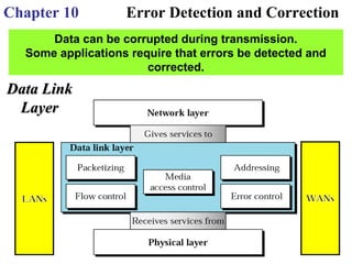
Data LinkData Link
LayerLayer
3. 10-1 INTRODUCTION10-1 INTRODUCTION
Types of error
Types of Errors
Redundancy
Detection Versus Correction
Forward Error Correction Versus Retransmission
Coding
Modular Arithmetic
Topics discussed in this section:Topics discussed in this section:
In a single-bit error, only 1 bit in the data unit has changed.
A burst error means that
2 or more bits in the
data unit have changed.
Figure 10.1
Single-bit error
Figure 10.2 Burst
error of length 8
4. Figure 10.3 The structure of encoder and decoder
To detect or correct errors, we need to send extra (redundant) bits with
data.
In modulo-N arithmetic, we use only the integers in the range 0 to N −1,
inclusive.
Figure 10.4
XORing of two
single bits or two
words
5. 10-2 BLOCK CODING10-2 BLOCK CODING
In block coding, we divide our message into blocks, each of k bits,In block coding, we divide our message into blocks, each of k bits,
calledcalled datawordsdatawords. We add r redundant bits to each block to make the. We add r redundant bits to each block to make the
length n = k + r. The resulting n-bit blocks are calledlength n = k + r. The resulting n-bit blocks are called codewordscodewords..
Error Detection
Error Correction
Hamming Distance
Minimum Hamming Distance
Topics discussed in this section:Topics discussed in this section:
Figure 10.6 Process of error detection in block coding
6. Figure 10.5 Datawords and codewords in block coding
Example 10.1
The 4B/5B block coding discussed in Chapter 4 is a good example
of this type of coding. In this coding scheme,
k = 4 and n = 5. As we saw, we have 2k
= 16 datawords and 2n
= 32
codewords. We saw that 16 out of 32 codewords are used for
message transfer and the rest are either used for other purposes or
unused.
7. Let us assume that k = 2 and n = 3. Table 10.1 shows the list of
datawords and codewords. Later, we will see how to derive a
codeword from a dataword.
Assume the sender encodes the dataword 01 as 011 and sends it to the
receiver. Consider the following cases:
1. The receiver receives 011. It is a valid codeword. The receiver
extracts the dataword 01 from it.
2. The codeword is corrupted during transmission, and 111 is
received. This is not a valid codeword and is discarded.
3. The codeword is corrupted during transmission, and 000 is
received. This is a valid codeword. The receiver incorrectly
extracts the dataword 00. Two corrupted bits have made the error
undetectable.
Example 10.2
8. Table 10.1 A code for error detection (Example 10.2)
An error-detecting code can detect only the types of errors
for which it is designed; other types of errors may remain
undetected.
Figure 10.7 Structure of
encoder and decoder in error
correction
9. Let us add more redundant bits to Example 10.2 to see if the receiver
can correct an error without knowing what was actually sent. We add
3 redundant bits to the 2-bit dataword to make 5-bit codewords.
Assume the dataword is 01. The sender creates the codeword 01011.
The codeword is corrupted during transmission, and 01001 is
received. First, the receiver finds that the received codeword is not in
the table. This means an error has occurred. The receiver, assuming
that there is only 1 bit corrupted, uses the following strategy to guess
the correct dataword.
Example 10.3
10. 1. Comparing the received codeword with the first codeword in the
table (01001 versus 00000), the receiver decides that the first
codeword is not the one that was sent because there are two
different bits.
2. By the same reasoning, the original codeword cannot be the
third or fourth one in the table.
3. The original codeword must be the second one in the table
because this is the only one that differs from the received
codeword by 1 bit. The receiver replaces 01001 with 01011 and
consults the table to find the dataword 01.
Example 10.3 (continued)
Table 10.2 A code
for error correction
(Example 10.3)
11. Let us find the Hamming distance between two pairs of words.
1. The Hamming distance d(000, 011) is 2 because
Example 10.4
2. The Hamming distance d(10101, 11110) is 3 because
The Hamming distance between two words is the
number of differences between corresponding bits.
The minimum Hamming distance is the smallest Hamming
distance between all possible pairs in a set of words.
Hamming Distance
12. Find the minimum Hamming distance of the coding scheme in
Table 10.1.
Solution We first find all Hamming distances.
Example 10.5
The dmin in this case is 2.
Example 10.6
Find the minimum Hamming distance of the coding scheme in
Table 10.2.
Solution We first find all the Hamming distances.
The dmin in this case is 3.
13. The minimum Hamming distance for our first code scheme (Table 10.1) is 2. This
code guarantees detection of only a single error. For example, if the third codeword
(101) is sent and one error occurs, the received codeword does not match any valid
codeword. If two errors occur, however, the received codeword may match a valid
codeword and the errors are not detected.
Example 10.7
Example 10.8
Our second block code scheme (Table 10.2) has dmin = 3. This code can detect up
to two errors. Again, we see that when any of the valid codewords is sent, two
errors create a codeword which is not in the table of valid codewords. The
receiver cannot be fooled.
However, some combinations of three errors change a valid codeword to another
valid codeword. The receiver accepts the received codeword and the errors are
undetected.
14. Figure 10.8 Geometric concept for finding dmin in error detection
Figure 10.9 Geometric concept for
finding dmin in error correction
To guarantee
correction of up
to t errors in all
cases, the
minimum
Hamming
distance in a
block code must
be dmin = 2t + 1.
To guarantee the
detection of up to s
errors in all cases, the
minimum Hamming
distance in a block
code must be dmin = s
+ 1.
15. A code scheme has a Hamming distance dmin = 4. What is the error detection and
correction capability of this scheme?
Solution
This code guarantees the detection of up to three errors
(s = 3), but it can correct up to one error. In other words,
if this code is used for error correction, part of its capability is wasted. Error
correction codes need to have an odd minimum distance (3, 5, 7, . . . ).
Example 10.9
16. 10-3 LINEAR BLOCK CODES10-3 LINEAR BLOCK CODES
Almost all block codes used today belong to a subset calledAlmost all block codes used today belong to a subset called linearlinear
block codesblock codes. A linear block code is a code in which the exclusive OR. A linear block code is a code in which the exclusive OR
(addition modulo-2) of two valid codewords creates another valid(addition modulo-2) of two valid codewords creates another valid
codeword.codeword.
Minimum Distance for Linear Block Codes
Some Linear Block Codes
Topics discussed in this section:Topics discussed in this section:
Table 10.2 A code
for error correction
(Example 10.3)
Table 10.1 A code for error
detection (Example 10.2)
17. Let us see if the two codes we defined in Table 10.1 and Table 10.2 belong to the
class of linear block codes.
1. The scheme in Table 10.1 is a linear block code
because the result of XORing any codeword with any
other codeword is a valid codeword. For example, the
XORing of the second and third codewords creates the
fourth one.
2. The scheme in Table 10.2 is also a linear block code.
We can create all four codewords by XORing two
other codewords.
Example 10.10
In our first code (Table 10.1), the numbers of 1s in the nonzero codewords are 2, 2,
and 2. So the minimum Hamming distance is dmin = 2. In our second code (Table
10.2), the numbers of 1s in the nonzero codewords are 3, 3, and 4. So in this code
we have dmin = 3.
Example 10.11
18. Table 10.3
Simple
parity-check
code C(5, 4)
A simple parity-check code is a single-bit error-detecting code in which
n = k + 1 with dmin = 2.
A simple parity-check code can detect an odd number of errors.
Simple Parity-Check Code
20. Let us look at some transmission scenarios. Assume the sender sends the dataword
1011. The codeword created from this dataword is 10111, which is sent to the
receiver. We examine five cases:
1. No error occurs; the received codeword is 10111.The syndrome is0. The dataword
1011 is created.
2. One single-bit error changes a1 . The received codeword is 10011. The syndrome is
1. No dataword is created.
3. One single-bit error changes r0 . The received codeword is 10110. The syndrome is
1. No dataword is created.
Example 10.12
4. An error changes r0 and a second error changes a3 . The received codeword is
00110. The syndrome is 0. The dataword 0011 is created at the receiver. Note tha
here the dataword is wrongly created due to the syndrome value.
5. Three bits—a3, a2, and a1—are changed by errors. The received codeword is
01011. The syndrome is 1.The dataword is not created. This shows that the simple
parity check, guaranteed to detect one single error, can also find any odd number of
errors.
All Hamming codes discussed in this book have dmin = 3. The relationship
between m and n in these codes is n = 2m − 1.
23. Error correcting codes
For Error correction we have to distinguish between only two
states
Error OR No Error
Also a bit has two states
1
0
So a Single bit parity can work, but if we want to correct the error
in a longer data ,two states are not enough
For example
To correct a single bit error in an ASCII character ,the error correction code
must determine which of 7 bit is in error
So there are 8 different states
No error
Error in position 1
Error in position 2
.
.
Error in position 7
3 bits are required to give only eight possibilities
24. Let m be the length of data and r be the length of redundancy bits
required to correct m bits
If the total number of bits in a transmittable unit is m+r
Then r must be able to indicate atleast m+r+1 different states
r bits indicates 2(r)
different states
2(r)
>= m+r+1
Error correcting codes
Number of
data bits
m
Number of
redundancy bits
r
Total
bits
m + r
11 2 3
22 3 5
33 3 6
44 3 7
55 4 9
66 4 10
77 4 11
Table 10.2 Data andTable 10.2 Data and
redundancy bitsredundancy bits
25. Creating Code word
The key to the Hamming Code is the use of extra parity bits to allow
the identification of a single error. Create the code word as follows:
Mark all bit positions that are powers of two as parity bits. (positions 1, 2, 4, 8,
16, 32, 64, etc.)
All other bit positions are for the data to be encoded. (positions 3, 5, 6, 7, 9, 10,
11, 12, 13, 14, 15, 17, etc.) Each parity bit calculates the parity for some of the
bits in the code word. The position of the parity bit determines the sequence of
bits that it alternately checks and skips.
Position 1: check 1 bit, skip 1 bit, check 1 bit, skip 1 bit, etc.
(1,3,5,7,9,11,13,15,...)
Position 2: check 2 bits, skip 2 bits, check 2 bits, skip 2 bits, etc.
(2,3,6,7,10,11,14,15,...)
Position 4: check 4 bits, skip 4 bits, check 4 bits, skip 4 bits, etc.
(4,5,6,7,12,13,14,15,20,21,22,23,...)
Position 8: check 8 bits, skip 8 bits, check 8 bits, skip 8 bits, etc. (8-15,24-
31,40-47,...)
Position 16: check 16 bits, skip 16 bits, check 16 bits, skip 16 bits, etc. (16-
31,48-63,80-95,...)
Position 32: check 32 bits, skip 32 bits, check 32 bits, skip 32 bits, etc. (32-
63,96-127,160-191,...)
etc.
26. We need a dataword of at least 7 bits. Calculate values of k and n
that satisfy this requirement.
Solution
We need to make k = n m greater than or equal to 7, or 2m 1− − −
m 7.≥
1. If we set m = 3, the result is n = 23 1 and k = 7 3,− −
or 4, which is not acceptable.
2. If we set m = 4, then n = 24 1 = 15 and k = 15 4 =− −
11, which satisfies the condition. So the code is
Example 10.14
C(15, 11)
10.14 Positions of redundancy bits in Hamming code
31. 10-4 CYCLIC CODES10-4 CYCLIC CODES
Cyclic codesCyclic codes are special linear block codes with one extra property. Inare special linear block codes with one extra property. In
a cyclic code, if a codeword is cyclically shifted (rotated), the result isa cyclic code, if a codeword is cyclically shifted (rotated), the result is
another codeword.another codeword.
Cyclic Redundancy Check
Polynomials
Cyclic Code Analysis
Advantages of Cyclic Codes
Other Cyclic Codes
Topics discussed in this section:Topics discussed in this section:
Table 10.6 A CRC code with C(7, 4)
35. Figure 10.21 A polynomial to represent a binary word
Figure 10.22 CRC
division using
polynomials
36. The divisor in a cyclic code is normally called the
generator polynomial or simply the generator.
In a cyclic code,
If s(x) ≠ 0, one or more bits is corrupted.
If s(x) = 0, either
a. No bit is corrupted. or
b. Some bits are corrupted, but the
decoder failed to detect them.
In a cyclic code, those e(x) errors that are divisible by
g(x) are not caught.
If the generator has more than one term and the
coefficient of x0
is 1, all single errors can be caught.
37. Which of the following g(x) values guarantees that a single-bit
error is caught? For each case, what is the error that cannot be
caught?
a. x + 1 b. x3
c. 1
Solution
a. No xi
can be divisible by x + 1. Any single-bit error can
be caught.
b. If i is equal to or greater than 3, xi
is divisible by g(x).
All single-bit errors in positions 1 to 3 are caught.
c. All values of i make xi
divisible by g(x). No single-bit
error can be caught. This g(x) is useless.
Example 10.15
Figure 10.23
Representation of two
isolated single-bit
errors using
polynomials
38. Find the status of the following generators related to two isolated,
single-bit errors.
a. x + 1 b. x4
+ 1 c. x7
+ x6
+ 1 d. x15
+ x14
+ 1
Solution
a. This is a very poor choice for a generator. Any two
errors next to each other cannot be detected.
b. This generator cannot detect two errors that are four
positions apart.
c. This is a good choice for this purpose.
d. This polynomial cannot divide xt
+ 1 if t is less than
32,768. A codeword with two isolated errors up to
32,768 bits apart can be detected by this generator.
Example 10.16
If a generator cannot divide xt
+ 1 (t between 0 and n – 1),
then all isolated double errors can be detected.
39. A generator that contains a factor of x + 1 can detect all odd-numbered errors.
❏ All burst errors with L ≤ r will be
detected.
❏ All burst errors with L = r + 1 will be
detected with probability 1 – (1/2)r–1
.
❏ All burst errors with L > r + 1 will be
detected with probability 1 – (1/2)r
.
A good polynomial generator needs to have the following characteristics:
1. It should have at least two terms.
2. The coefficient of the term x0
should be 1.
3. It should not divide xt
+ 1, for t between 2 and n − 1.
4. It should have the factor x + 1.
It should be divisible by x+1.This Guarantees that all burst errors
affecting an odd number of bits are detected
Table 10.7
Standard
polynomials
40. Find the suitability of the following generators in relation to burst
errors of different lengths.
a. x6
+ 1 b. x18
+ x7
+ x + 1 c. x32
+ x23
+ x7
+ 1
Solution
a. This generator can detect all burst errors with a length less than
or equal to 6 bits; 3 out of 100 burst errors with length 7 will slip
by; 16 out of 1000 burst errors oflength 8 or more will slip by.
Example 10.17
b. This generator can detect all burst errors with a length less than or
equal to 18 bits; 8 out of 1 million burst errors with length 19 will slip
by; 4 out of 1 million burst errors of length 20 or more will slip by.
c. This generator can detect all burst errors with a length less than or
equal to 32 bits; 5 out of 10 billion burst errors with length 33 will slip
by; 3 out of 10 billion burst errors of length 34 or more will slip by.
41. 10-5 CHECKSUM10-5 CHECKSUM
The last error detection method we discuss here is called the checksum.The last error detection method we discuss here is called the checksum.
The checksum is used in the Internet by several protocols although notThe checksum is used in the Internet by several protocols although not
at the data link layer. However, we briefly discuss it here to completeat the data link layer. However, we briefly discuss it here to complete
our discussion on error checkingour discussion on error checking
Example 10.18
Suppose our data is a list of five 4-bit numbers that we want to send
to a destination. In addition to sending these numbers, we send the
sum of the numbers. For example, if the set of numbers is (7, 11,
12, 0, 6), we send (7, 11, 12, 0, 6, 36), where 36 is the sum of the
original numbers. The receiver adds the five numbers and
compares the result with the sum. If the two are the same, the
receiver assumes no error, accepts the five numbers, and discards
the sum. Otherwise, there is an error somewhere and the data are
not accepted.
42. We can make the job of the receiver easier if we send the negative
(complement) of the sum, called the checksum. In this case, we
send (7, 11, 12, 0, 6, −36). The receiver can add all the numbers
received (including the checksum). If the result is 0, it assumes no
error; otherwise, there is an error.
Example 10.19
Example 10.20
How can we represent the number 21 in one’s complement
arithmetic using only four bits?
Solution
The number 21 in binary is 10101 (it needs five bits). We can wrap
the leftmost bit and add it to the four rightmost bits. We have (0101
+ 1) = 0110 or 6.
43. How can we represent the number −6 in one’s complement
arithmetic using only four bits?
Solution
In one’s complement arithmetic, the negative or complement of a
number is found by inverting all bits. Positive 6 is 0110; negative 6
is 1001. If we consider only unsigned numbers, this is 9. In other
words, the complement of 6 is 9. Another way to find the
complement of a number in one’s complement arithmetic is to
subtract the number from 2n
1 (16 1 in this case).− −
Example 10.21
44. Let us redo Exercise 10.19 using one’s complement arithmetic. Figure
10.24 shows the process at the sender and at the receiver. The sender
initializes the checksum to 0 and adds all data items and the checksum
(the checksum is considered as one data item and is shown in color).
The result is 36. However, 36 cannot be expressed in 4 bits. The extra
two bits are wrapped and added with the sum to create the wrapped
sum value 6. In the figure, we have shown the details in binary. The
sum is then complemented, resulting in the checksum value 9 (15 − 6 =
9). The sender now sends six data items to the receiver including the
checksum 9.
Example 10.22
The receiver follows the same procedure as the sender. It adds all data
items (including the checksum); the result is 45. The sum is wrapped
and becomes 15. The wrapped sum is complemented and becomes 0.
Since the value of the checksum is 0, this means that the data is not
corrupted. The receiver drops the checksum and keeps the other data
items. If the checksum is not zero, the entire packet is dropped.
46. Receiver site:
1. The message (including checksum) is divided into 16-bit
words.
2. All words are added using one’s complement addition.
3. The sum is complemented and becomes the new
checksum.
4. If the value of checksum is 0, the message is accepted;
otherwise, it is rejected.
Sender site:
1. The message is divided into 16-bit words.
2. The value of the checksum word is set to 0.
3. All words including the checksum are added using one’s
complement addition.
4. The sum is complemented and becomes the checksum.
5. The checksum is sent with the data.
47. Let us calculate the checksum for a text of 8 characters
(“Forouzan”). The text needs to be divided into 2-byte (16-bit)
words. We use ASCII (see Appendix A) to change each byte to a 2-
digit hexadecimal number. For example, F is represented as 0x46
and o is represented as 0x6F. Figure 10.25 shows how the
checksum is calculated at the sender and receiver sites. In part a of
the figure, the value of partial sum for the first column is 0x36. We
keep the rightmost digit (6) and insert the leftmost digit (3) as the
carry in the second column. The process is repeated for each
column. Note that if there is any corruption, the checksum
recalculated by the receiver is not all 0s. We leave this an exercise.
Example 10.23