ISYU TUNGKOL SA SEKSWLADIDA (ISSUE ABOUT SEXUALITY
Renewable energy course#05
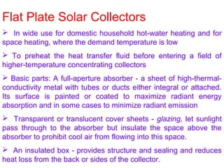
1. Flat Plate Solar Collectors
In wide use for domestic household hot-water heating and for
space heating, where the demand temperature is low
To preheat the heat transfer fluid before entering a field of
higher-temperature concentrating collectors
Basic parts: A full-aperture absorber - a sheet of high-thermal-
conductivity metal with tubes or ducts either integral or attached.
Its surface is painted or coated to maximize radiant energy
absorption and in some cases to minimize radiant emission
Transparent or translucent cover sheets - glazing, let sunlight
pass through to the absorber but insulate the space above the
absorber to prohibit cool air from flowing into this space.
An insulated box - provides structure and sealing and reduces
heat loss from the back or sides of the collector.
3. Absorber Plate
3- Functions: absorb the maximum possible amount of solar
irradiance, conduct this heat into the working fluid at a minimum
temperature difference, and lose a minimum amount of heat
back to the surroundings.
Absorption. Surface coatings having high absorptance for short-
wavelength (visible) light, are used. Appear dull or "flat,"
absorbing radiation from all directions. Either paint or plating is
used, typically absorb over 95 percent of the incident solar
radiation.
Fin Heat Removal. Metal sheet acts as fin to bring absorbed heat
into the fluid. Heat conducted to tubes or ducts that contain the
heat-transfer fluid - a liquid (water or water with antifreeze) or
gas (air). Important design criterion - high heat transfer
capability at low ΔT between absorber plate and working fluid.
Require pumping power and expensive absorber plate material.
Liquid absorber plates - a flat sheet of metal with tubes spaced
10-25 cm apart and attached (integral, brazed or press fitted).
4. Good ‘tube and sheet’ absorber:
The fin should be thick to minimize ΔT required to transfer heat to
its base (tube).
Tubes should not be spaced too far apart
Tubes should be thin-walled and of high-thermal-conductivity
material.
The fin (absorber sheet) must be made of material with high
thermal conductivity.
Tube should be brazed or welded to the absorber sheet to
minimize thermal contact resistance.
Tube and absorber sheet should be of similar material to prevent
galvanic corrosion between them.
For air as HTF, back side of the absorber plate forms one surface of
a duct and heat is transferred through the absorber sheet to the air
over the entire back surface of the absorber. A thin absorber sheet of
high-thermal-conductivity material desired. The internal air passage
must allow high airflow at the back of the absorber without producing a
high pressure drop across the collector, which will cause high pumping
power for fans supplying the air.
5. Emittance.
Since the temperature of the absorber surface is above Tamb, the
surface re-radiates some of the heat it has absorbed. This loss
mechanism is a function of the emittance of the surface for low-
temperature, long-wavelength (infrared) radiation.
Dilemma - many coatings that enhance the absorption of sunlight
(short-wavelength radiation) also enhance the long wavelength
radiation loss from the surface - for most dull black paints.
A class of coatings, mostly produced by metallic plating
processes, produce an absorber surface that is a good absorber
of short-wavelength solar irradiance but a poor emitter of long-
wavelength radiant energy.
Flat-plate absorbers that have selective surfaces typically lose less heat
when operating at high temperature. However, the absorptance of
selective coatings is seldom as high as for non-selective coatings, and a
tradeoff must be made based on whether the increased high-
temperature performance overshadows the reduced low-temperature
performance and expense of the selective coating.
6. Cover Sheets
One or more transparent or translucent cover sheets to reduce
convective heat loss
Convective loss not completely eliminated due to convective current
between the absorber and the cover sheet
External convection cools the cover sheet, producing a net heat loss
from the absorber
Heat loss is further reduced due to thermal resistance of the added air
space & Green House Effect
Number of Covers. From none to three or more
Collectors with no cover sheet have high efficiencies at near ambient
temperature (e.g. swimming pools with ΔT < 10 o
C) - incoming energy
is not lost by absorption or reflection by the cover sheet
Increases in the number of cover-sheets increases the temperature at
which the collector can operate (or permits a given temperature to be
reached at lower solar irradiance)
One or two cover sheets are common - triple glazed collectors used
for extreme climates
Each added cover sheet increases the collection efficiency at high
temperature but decreases efficiency at low temperatures
7. Cover Sheets
For regions of average mid-latitude temperatures and solar radiation
collectors with no glazing generally used for applications to 32ºC
single-glazed collectors are used for applications to 70ºC
double-glazing is used in applications above 70ºC
collector efficiency increases with increasing solar irradiance level but
decreases with increasing operating temperature
Materials. Tempered glass with low iron content and 3.2-6.4 mm
thickness is used as outer cover sheet due to superior resistance to the
environment,
Surface may be either smooth, making the glass transparent, or with
a surface pattern, making it translucent. Both types have a
transmittance of around 90 per cent.
Plastic cover sheets are sometimes used for the second cover sheet
when two sheets are required. Glass also does not transmit UV radiation
and thus protects the plastic
Rigid sheets of acrylic-or fiberglass-reinforced polymers or stretched
films of polyvinyl fluoride are used
A major draw back of this scheme is the potential for overheating the
plastic sheet at collector stagnation (no-flow) temperatures
8. Advantages
Absorb energy coming from all directions above the absorber
(both beam and diffuse solar irradiance)
Do not need to track the sun
Receive more solar energy than a similarly oriented
concentrating collector, but when not tracked, have greater
cosine losses
May be firmly fixed to a mounting structure, and rigid
plumbing may be used to connect the collectors to the
remainder of the system
To increase their output, they may be repositioned at
intervals or placed on a single- or two-axis tracking
mechanism
They absorb both the direct and the diffuse components (~
10% of the normal) of solar radiation on cloudless days
On a cloudy day almost all of the available solar irradiance is
diffuse
9. Collectible Solar Radiation Comparison Between
Flat-Plate and Concentrating Collectors
Annual Average Daily
Solar Radiation (MJ/m2
)
Collector Albuquerque Madison
Two-axis tracking flat-
plate collector
(direct plus diffuse)
31 19.5
Fixed, latitude-tilt flat-
plate collector (direct
plus diffuse)
23 15
Two-axis tracking
concentrator
(direct only)
26.5 14
10. Collector Performance
Orientation
Azimuth
South facing – for a fixed surface in the northern hemisphere
If the industrial demand is greater in the morning the azimuth may be
rotated to the east
It is generally accepted that the azimuth of a fixed field may be rotated
up to 15 degrees from south and not make a significant difference in
the overall energy collection
Tilt.
Most logical tilt angle for the fixed flat-plate collector is to tilt equal to
the latitude angle
The noontime sun will only vary above and below this position by a
maximum angle of 23.5 degrees
However if the demand is greater in the winter months, tilting may be
more towards the horizon while accepting the summer energy loss
Collector tilt optimization is not critical and that even horizontal
surfaces may be an appropriate design choice if the cost of
installation is considerably less for this orientation
12. Efficiency Measurement
Energy collection efficiency is normally determined by testing
collector performance
Test data are correlated with a parameter comprised of the
collector temperature rise above ambient divided by the solar
irradiance
Collector temperature used for flat-plate collector performance
correlation is normally the temperature of the heat-transfer fluid
entering the collector, not the average fluid temperature
Must specify the fluid flow rate at which the measurements
were made
Recommended test flow rate for a liquid collector is 0.02 kg/hr
(14.7 lb/hr ft2) and for an air collector, 0.01 m3/s m2 (1.97 cfm/ft2)
at atmospheric pressure.
Aperture irradiance is the global (total) solar irradiance
measured in the plane of the collector
some ground reflection if the collector is tilted from the
horizontal as is usually the case
13. Typical Performance of Flat Plate Collectors
Fr = Heat Removal Efficiency
ηopt = Optical Efficiency
UL = Heat Loss Coefficient
14. Comparison with Parabolic Troughs
Treadwell (1979) used TMY (Typical Meteorological Year)
weather data for 26 sites
A field of single glazed flat-plate collectors with selective
absorber surfaces compared with a field of commercial parabolic
trough concentrators
Both horizontal and latitude-tilt south-facing orientations for the
flat-plate collectors were considered
Both north-south and east-west tracking axis orientations
considered for the parabolic trough collectors
The typically higher optical efficiency of the flat-plate collector
compensated only partially for the higher thermal efficiency of the
concentrators
Over a full year’s operation, the north-south trough orientation
and the latitude-tilt flat-plate orientations provided the most energy
Troughs and flat-plate collectors have equivalent performance
at about 49ºC in the southwestern region, and at 66ºC in most of
the southeastern region.
15. Temperature Contours of Equal Performances for Flat
Plate Collectors & Parabolic Trough Concentrators
16. Industrial Process Heat Systems in USA Using
Flat-Plate Collectors (Hot Water)
Company Process Application Temperature
(ºC)
Area
(m2
)
Anhauser-Busch,
Inc.
Beer pasteurization 60ª 427
Aratex Services, Inc. Heat process water 50 -70 624
Berkeley Meat Co. Sanitation 82 232
Campbell Soup Co. Preheat can wash
water
91 372
Coca-Cola Bottling
Co.
Bottle washing NAª 881
Easco Photo Film processing 46 NA
General Extrusion,
Inc.
Solution heating 71-82ª 409
Iris Images Film processing 24-38 59
17. Jhirmack
Enterprises, Inc.
Preheat boiler water 71-93 622
Mary Kay Cosmetics Sanitizing 60 305
Riegel Textile Corp. Heat dye-beck water 88ª 621
Spicer Clutch
(Dana)
Parts washing 54 87
Gilroy Foods, Inc. Preheat drier air/
boiler feedwater
90 553
Gold Kist, Inc. Preheat drier air b
82 1217
LaCour Kiln
Services
Lumber drying 82 234
Lamanuzzi &
Pantaleo
Raisin drying 62 1951
Company Process Application Temperature
(ºC)
Area
(m2
)
19. Solar Ponds
The least expensive type of solar collector
Primarily for large industrial applications - cost
decreases considerably with increases in size
Shallow Ponds:
Consist of a group of collectors made of black plastic
liners lying on top of insulation that has been laid on flat
graded ground
At least one translucent cover sheet (un-seamed,
weather-able plastic sheets) above water bag, supported
by side curbs
Water is pumped into the collectors from underground
storage tank
Can attain temperatures of up to 60º
Heated water pumped to an industrial demand or a
21. Salt-Gradient Ponds
Employs a salt concentration gradient to suppress natural
convection
Heated water holds more dissolved salt than does cooler water
Salty, heated water is heavier - remains at the bottom of the
solar pond
Three zones
(1) Surface convective zone - low-salinity water, ~ 0.2-0.4 m thick
(2) Non-convective/salinity-gradient zone - salt concentration
increases with depth ~ 1.0-1.5 m thick
(3) Storage zone - bottom - uniformly high salt concentration ~ 1-3
m thick
Hot brine is drawn from the storage zone and pumped through
a heat exchanger and back to the storage zone
For Rankine cycle, condenser cooling water is drawn off the
top of the pond and passed through the condenser and back to
the surface, where it cools
23. If the Solar Radiation Intensity on the horizontal surface is 600 watts and the Sun’s
altitude angle is 30o
, while a reflector is tilted at an angle of 85o
from the horizontal
direction, what will be the combined intensity of the reflected and incident light on the
horizontal surface ?
30o 85o
I
Horizontal Surface
ReflectorSolar Altitude
Tilt Angle
Quiz
24. Thermal Collector Capture and Loss Mechanisms
Energy balance on a solar collector absorber or receiver is;
Quseful = Eopt – QLoss (W)
Quseful - Rate of ‘useful’ energy leaving the absorber (W)
Eopt - Rate of optical (short wavelength) radiation incident on
absorber (W)
QLoss - Rate of thermal energy loss from the absorber (W)
‘Useful’ energy is the rate of energy being added to a heat transfer
fluid (HTF)
Quseful = m●
Cp (Tout - Tin) (W)
m●
- mass flow rate of HTF (kg/s)
Cp - specific heat of HTF (J/kg.K)
Tout - temperature of HTF leaving the absorber
T - temperature of HTF entering the absorber
25. Optical Energy Capture
Einc = Ia Aa (W)
Ia - Solar irradiance entering the collector aperture (global (total)
or direct (beam))(W/m2
)
Aa - Aperture area of the collector (m2
)
Rate of optical (short wavelength) energy reaching the absorber or
receiver is:
Eopt = Γ ρ α τ Ia Aa
Γ - Capture fraction (fraction of reflected energy entering or
impinging on receiver)
ρ - Reflectance of any intermediate reflecting surfaces
τ - Transmittance of any glass or plastic cover sheets or windows
α - Absorptance of absorber or receiver surface
The first two terms above apply only to concentrating collectors
26. Four important mechanisms that reduce the amount of solar
energy that is incident on the collector aperture; imperfect
reflection, imperfect geometry, imperfect transmission and
imperfect absorption
Capture fraction is a measure of both the quality of the shape of
the reflecting surface, and the size of the receiver. A poorly
shaped concentrator, or a receiver too small will make this
number considerably less than 1.0
Properly designed concentrators have capture fractions > 0.95,
and silver/glass mirrors can have a reflectance of 0.94 and new
aluminum reflecting surfaces have a reflectance of about 0.86.
The transmittance is the average overall transmittance and
represents the total reduction in transmitted energy in the solar
spectrum by all covers
Transmittance of the cover also depends on the wavelength of
light passing through it. Glass for example transmits most
radiation in the visible spectrum, but does not transmit much in the
infrared region
27. Plastic covers have high transmittance values at very long
wavelengths
Absorption term represents the fraction of solar energy incident
upon the surface, that is absorbed (the remainder being reflected).
A good black surface can have an absorption > 0.98, however, as
surfaces degrade, this value can decrease
For most real surfaces, the absorption varies as a function of
the wavelength of the incident energy. ‘selective surfaces’ have a
higher absorptance in the visible spectrum than at longer
wavelengths, thereby reducing thermal radiation loss
28. Heat Loss Mechanisms
QLoss = QConvection + QRadiation + QConduction
The balance between heat removal and heat loss defines the
operating temperature of the collector
For concentrating collectors, when not enough heat is being
removed, the temperature of the absorber can increase to its
melting temperature
Approximate Convection Loss
QConvection = hc Ar (Tr – Ta)
hc - Average overall convective heat transfer coefficient (W/m2
.K)
Ar - Surface area of receiver or absorber (m2
)
Tr - Average temperature of receiver (K)
T - Ambient air temperature (K)
29. Radiation Loss
Important for collectors operating at temperatures only slightly above
ambient
Becomes dominant for collectors operating at higher temperatures
QRadaition = ε σ Ar (Tr
4
– Tsky
4
)
ε - Emittance of the absorber surface
σ - Stefan-Boltzmann constant (5.670 × 10⁻⁸
W/m2
K4
)
Tsky- Equivalent black body temperature of the sky (K)
Black, Vertical Surface in Free Air at 25o
C.
Radiation
Convection
30. Conduction Loss
QConduction = K Ar (Tr – Ta) / Δx
K - Equivalent average conductance (W/m.K)
Δx - Average thickness of insulating material
Usually small compared to convection and radiation losses
In flat-plate collectors, the sides and back surface of the
absorber plate should incorporate good insulation (low k) and the
insulation should be thick enough to render this heat loss
insignificant.
31. Selective Surfaces
From radiation heat transfer theory - for black body and gray
surfaces, the absorptance equals the emittance
However for all surfaces, Kirchoff’s Law states that they are equal
only for radiation at a specific wavelength, not as an average
property integrated over a spectrum
Kirchoff’s law αλ = ελ
Subscript indicates that these are ‘spectral’ properties and must
be integrated over all wavelengths
If the spectrums are different, the integrated properties can be
different. In solar collectors, the spectrum of the energy being
absorbed is from a 6,050K black body emitter with peak intensity
at a wavelength of 0.48 microns. The spectrum of the energy
being emitted by the absorber / receiver is defined by the
temperature of the absorber surface
32. if the receiver surface temperature is 80o
C, the peak intensity is
at a wavelength of 8.21 microns.
Selective surfaces have a high absorptance (and emittance) for
short wavelength (visible) light and have low average absorptance
and emittance for long wavelength radiation (thermal or infra-red
radiation).
They do not violate Kirchoff’s law, however, we say that they
have ‘high absorptance and low emittance’ meaning high
absorption for short wavelength radiation, and low emittance for
long wavelength radiation. The end result is a surface that
absorbs solar energy well, but does not radiate thermal energy
very well
34. Selective Coatings
Consider a hypothetical surface with 0.95 absorptance at
wavelengths shorter than 5 microns and 0.25 for longer
wavelengths. Since 99.5% of solar energy occurs at wavelengths
below 5 microns, the effective absorptance of such a surface is
0.965
The integrated emittance for this hypothetical surface depends on
its temperature. If this surface is 80o
C, 99.1% of its radiant energy
is at wavelengths above 5 microns and the integrated emittance
for this surface is 25.6%
On the other hand, If the absorber surface is at a temperature of
700o
C as is typical for receivers in parabolic dish concentrating
collectors, only 43.6 % of its radiated energy is at wavelengths
above 5 microns and the integrated emittance is 64.5%.
Black Chrome. Tyically, a thin (2-3 μm thick) black chrome
coating (α= 0.95) is electro-deposited on a mild steel receiver tube
that has been electroplated with 25 μm of bright nickel (ε=0.25)
35. Photovoltaic Panel Capture and Loss Mechanisms
An energy balance on a photovoltaic panel provides less useful
information to the solar energy system designer
The PV cell efficiency decreases with increases in panel
temperature
Rate of heat loss from the panel should be high rather than low
Pelectric = I x v = Eopt - Qloss
Physical limit to the fraction of useful energy that can be produced
from the incident optical radiation 1 – 30%, requiring that the rest
of the 70% to 99% of the incident energy, be lost through heat
loss mechanisms
Optical Energy Capture
Eopt = Γ ρ α τ Ia Aa
For a concentrating photovoltaic panel
37. At low values of load resistance, the current is a maximum and
the voltage across the cell approaches zero. The current output
at zero voltage is short-circuit current, Isc - a function of the
size of the PV cell, and the number of cells connected in
parallel.
Isc is also directly proportional to the level of solar irradiance -
PV cells can be used as transducers to measure solar irradiance
As the load resistance increases, the current decreases slightly
until the cell can no longer maintain a high current level, and it
falls to zero - open-circuit voltage, Voc. Note that Voc varies
only a small amount as a function of solar irradiance (except at
very low levels)
A single silicon PV cell produces Voc of slightly over 0.55 volts
Peak Power Point (PPP) As the load resistance increases from
the Isc condition, the voltage rises until the I-V curve starts falling
to the open circuit point. There is a point along the curve where
the maximum power is generated which occurs just as the I-V
38. Peak Power Point of PV at Different Solar
Irradiance ~ 80% of Voc – peak power trackers
39. PV Temperature Loss ~ -4% Voc and +0.5% Isc
for a 10o
C change in cell temperature
40. Collector Efficiency
ηcol = Quseful / Ia Aa
Optical Efficiency
ηopt = Γ ρ τ α
Flat-plate Collectors
ηcol = m●
cp (Tout – Tin) / Ig Aa
Where Ig is global Irradiance
Concentrating Collectors
ηcol = m●
cp (Tout – Tin) / Ib cos θi Aa
Where Ib is direct beam Irradiance
Concentrating PV Collectors
ηcol = I . V / Ib cos θi Aa
47. Measuring Collector Performance
Collector test standards specify both the experimental setup and
the testing procedure
Testing is performed only on clear days when the solar
irradiance level is high and constant
Prior to taking measurements, hot HTF is circulated through the
absorber or receiver to bring it up to the test temperature
For a flat-plate collector, the test flow rate is generally specified
by the test procedure in use
In case of parabolic trough testing, turbulent flow is maintained
within the receiver tube to ensure good heat transfer between
the fluid and the wall of the receiver tube
A measurement is made only when the collector is at steady
state, which is indicated by a constant rise in heat transfer fluid
as it flows through the receiver
48. Thermal Performance Measurements
Collector aperture is aligned as close as possible to normal to
the incident direct (beam) solar irradiance
Once data are obtained with the aperture normal to the sun,
testing is repeated, usually only at one temperature, to
determine the effect of varying angles of incidence on collector
performance
3 – Procedures for Performance Measurement
1. Collector Balance
2. System Balance
3. Heat Loss Measurement
49. Inlet and Outlet
Temperatures
and flow rate
measured
Rate of change
of temperature
of insulated
water reservoir
measured
First, rate of
optical energy
collected is
measured near
ambient temp.
Most
Common
Test for Flat
Plate and
Parabolic
Trough
Then heat loss is
measured at
different
temperatures in
shade using a
heater
1
2
3
50. Incident Angle Modifier - Ki
Ratio of collector efficiency at any angle of incidence, to
that at normal incidence
Ki = ηopt, θi / ηopt, n = a θi + b θi
2
ηcol = Ki ηopt,n
52. Concentration Ratio
Collector Stagnation Temperature - The receiver
temperature at which convective and radiation heat
loss from the receiver = absorbed solar energy
Optical Concentration Ratio (CRo): The averaged
irradiance (Ir) integrated over the receiver area (Ar),
divided by the insolation incident on the collector
aperture.
CRo = [⌠ Ir dAr / Ar ] / Ia
Geometric Concentration Ratio (CRg): The area of the
collector aperture Aa divided by the surface area of the
receiver A CR = A / A
54. Parabolic Geometry
y2
= 4 f x
with origin at V
Sin2
θ /Cos θ = 4 f / r
in polar coordinates
with origin at V
p = 2 f / (1 + cos
ψ)
with origin at F
56. h = d2
/ 16 f
d
f
tan ψrim = 1 / [(d/8h) - (2h/d)]
tan (ψrim / 2) = 1 / 4(f/d)
f/d = (1 + cos ψrim ) / 4sin ψrim
ψrim
A = 2 d h / 3
Arc length = s = [ d √ (4h/d)2
+ 1 / 2] + 2f ln [4h/d + √ (4h/d)2
+ 1]
s
57. Paraboloid
The surface formed by rotating a parabolic curve about its axis is
called a paraboloid of revolution. Solar concentrators having a
reflective surface in this shape are often called parabolic dish
concentrators.
X2
+ Y2
= 4fz
In rectangular coordinates
with the z-axis as the axis
of symmetry
Z = a2
/ 4f
In cylindrical coordinates,
where a is the distance
from the z-axis
58. circular differential area strip on the paraboloid
dAs = 2 π a √ dz2
+ da2
(m2
)
= 2 π a √ 1 + (a / 2f)2
da (m2
)
60. Circular Mirror
Parallel rays reflected from a
circular mirror pass through a
line drawn through the center
of the circle and parallel to the
incident rays
A circular mirror is symmetrical
with respect to rotations about
its center
61. Parabolic Mirror
A parabolic mirror is not symmetrical to rotations about its focal
point. If the incident beam of parallel rays is even slightly off
normal to the mirror aperture, beam dispersion occurs, resulting in
spreading of the image at the focal point. For a parabolic mirror to
focus sharply, therefore, it must accurately track the motion of the
sun.
62. Angles for reflection from a cylindrical (or spherical)
mirror – θ1 = θ2 = θ3
Point PF is termed the paraxial focus. As increases, the reflected
ray crosses the line below PF. The spread of the reflected image
as θ3 increases, is termed spherical aberration.
For practical
applications, if the rim
angle ψrim of a
cylindrical trough is
kept low (<20-30o
),
spherical aberration is
small and a virtual line
focus trough is
achieved
63. Focusing of parallel rays of light using circular mirrors
with different rim angles
65. Reflection of a light
ray from a
parabolic mirror
dAs = l ds
l = either length of a
differential strip on the
surface of a parabolic
trough along the
direction of the focal
line,
or circumference of
the differential ring on
the surface of a
parabolic dish
ds = p sin(dψ)/ cos(ψ/2)
66. Total radiant flux reflected from a differential area
to the point of focus:
dΦ = dAs Ib cos (ψ/2) = l p Ib dψ (for small ψ)
= 2 f l Ib dψ / (1 + cos ψ) as p = 2 f / (1+ cos ψ)
dΦPT = 2 f l Ib dψ / (1 + cos ψ) for Parabolic Trough
dΦPD = 8π Ib f2
sin ψ dψ/ (1 + cos ψ)2
for Parabolic Dish
as l = 2πp sin ψ
69. Snell’s Law
s-polarized light – Electric field is in the plane of the
interface
p-polarized light - Electric field is in a perpendicular
direction to s-polarized