Vilken riktning tar rekryteringen i närmaste framtid?
UKCS-23rd-round-Anergy_text
1. Anergy Ltd – Application 23rd
Offshore Round UKCS
23rd
Concession Round Page 1 of 75
Geological and Technological Evaluation
23rd
Offshore Concession Round
UKCS
JUNE 2005
2. Anergy Ltd – Application 23rd
Offshore Round UKCS
23rd
Concession Round Page 2 of 75
Geological and Technological Evaluation
List of content
1 EXECUTIVE SUMMARY........................................................................................................................ 7
1.1 GENERAL INFORMATION ................................................................................................................... 7
1.2 BLOCKS APPLIED FOR........................................................................................................................ 8
1.3 BLOCK SUMMARIES........................................................................................................................... 8
1.3.1 211/19b and 211/24c ..........................................................................................8
1.3.2 Block 211/11B ................................................................................................12
1.4 WORK PROGRAMME FRAMEWORK ................................................................................................... 14
1.5 COMMENTS TO APPLICATION.......................................................................................................... 14
1.5.1 Blocks 211/19b and 211/24c.......................................................................14
1.5.2 Block 211/11b.................................................................................................15
2 INTRODUCTION................................................................................................................................... 16
2.1 REPORT ORGANISATION .................................................................................................................. 16
2.2 WORK PROCESSES AND METHODOLOGY........................................................................................... 16
2.2.1 Data Management .........................................................................................16
2.2.2 Software ..........................................................................................................17
2.2.3 Development scenarios ................................................................................17
3 EVALUATION OF BLOCKS 211/19b and 211/24c ............................................................................... 18
3.1 REGIONAL GEOLOGICAL OF NORTHERN TAMPEN SPUR PROVINCE .................................................... 18
3.1.1 Tectonostratigraphic development..............................................................18
3.1.2 Exploration opportunities ..............................................................................20
3.2 DATABASE...................................................................................................................................... 21
3.2.1 Seismic data ...................................................................................................21
3.2.2 Well data..........................................................................................................22
3.3 PETROLEUM GEOLOGICAL ANALYSIS ............................................................................................... 22
3.3.1 Well ties and seismic interpretation ............................................................22
3.3.2 Depth conversion ...........................................................................................24
3.3.3 Attribute mapping...........................................................................................25
3.3.4 Structural and stratigraphic framework.......................................................26
3.4 IDENTIFIED EXPLORATION OPPORTUNITIES....................................................................................... 28
3.4.1 Introduction .....................................................................................................28
3.4.2 Prospect Aladdin............................................................................................30
3.4.3 Lead Ali............................................................................................................33
3.4.4 Prospect Jasmine ..........................................................................................34
3.4.5 Leads Lago, Lago South and Abu...............................................................37
3.4.6 Leads Jafar and Sultan .................................................................................39
3.4.7 Lead Genie......................................................................................................41
3.5 TIME CRITICAL DEVELOPMENT OF RESOURCES IN 211/19B AND 24C BLOCK AREA............................. 42
3.5.1 Introduction .....................................................................................................42
3.5.2 Pressure development in Tampen Spur.....................................................42
3.5.3 Consequence of Statfjord Field pressure depletion .................................45
3.5.4 Summary .........................................................................................................46
3.6 RESERVOIR TECHNOLOGY ............................................................................................................... 46
3.7 TECHNOLOGICAL ASSUMPTIONS ...................................................................................................... 48
3.8 PLAN FOR EXPLORATION ................................................................................................................. 50
4 EVALUATION OF BLOCK 211/11B..................................................................................................... 51
4.1.1 Exploration opportunities ..............................................................................52
4.2 DATABASE...................................................................................................................................... 52
4.2.1 Seismic data ...................................................................................................52
3. Anergy Ltd – Application 23rd
Offshore Round UKCS
23rd
Concession Round Page 3 of 75
Geological and Technological Evaluation
4.2.2 Well data..........................................................................................................52
4.3 IDENTIFIED EXPLORATION OPPORTUNITIES..................................................................................... 54
4.4 RESERVOIR TECHNOLOGY AND TECHNOLOGICAL ASSUMPTIONS.................................................... 72
4.5 PLAN FOR EXPLORATION ................................................................................................................ 72
5 REFERENCES........................................................................................................................................ 73
4. Anergy Ltd – Application 23rd
Offshore Round UKCS
23rd
Concession Round Page 4 of 75
Geological and Technological Evaluation
List of Figures
Figure 1.3-1 Prospect and leads in block 211/24c
Figure 1.3-2 Prospect and leads in block 211/19b
Figure 1.3-3 Prospect and leads in blocks 211/11b
Figure 3.1-1 Location and Tectonic Elements Map, Block 211/24c
Figure 3.1-2 General Stratigraphy of the Northern Viking Graben
Figure 3.1-3 Middle Jurassic Palaeogeography, North Sea
Figure 3.1-4 Early Late Jurassic Palaeogeography, North Sea
Figure 3.1-5 Lithostratigraphy Upper Jurassic Sequence
Figure 3.1-6 J40 Palaeogeography, Northern North Sea
Figure 3.1-7 J50 Palaeogeography, Northern North Sea
Figure 3.1-8 J60 Palaeogeography, Northern North Sea
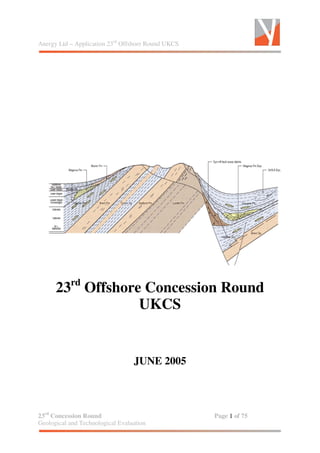
Figure 3.1-9 Geological Cross Section Northern North Sea
Figure 3.1-10 Lithostratigraphy North Sea
Figure 3.1-11 Borg Field Location map
Figure 3.1-12 Borg Field - Seismic line Upper Jurassic section
Figure 3.1-13 Borg Field - Seismic line Upper Jurassic section
Figure 3.1-14 Borg Field - Sand distribution
Figure 3.1-15 Borg Field - Paleogeographic setting
Figure 3.1-16 Lithostratigraphy - Lower Cretaceous
Figure 3.2-1 Seismic database, Block 211/24c
Figure 3.2-2 Well database, Block 211/24c
Figure 3.3-1 Synthetic Well Tie – Well 33/9-14
Figure 3.3-2 Synthetic Well Tie – Well 33/9-15
Figure 3.3-3 Synthetic Well Tie – Well 33/9-16
Figure 3.3-4 Top Lower Cretaceous Wedge, Time Structure Map, Block 211/24c
Figure 3.3-5 Lower Cretaceous, Time Structure Map, Block 211/24c
Figure 3.3-6 Lower Cretaceous, Isopach Map, Block 211/24c
Figure 3,3-7 Lower Cretaceous Wedge, Isopach Map, Block 211/24c
Figure 3.3-8 Base Cretaceous Unconformity, Time Structure Map, Block 211/24c
Figure 3.3-9 Intra Kimmeridgian Fm Unit 2, Time Structure Map, Block 211/24c
Figure 3.3-10 Intra Kimmeridgian Fm Unit 2, Depth Structure Map, Block 211/24c
Figure 3.3-11 Intra Kimmeridgian Fm Unit 2, Isopach Map, Block 211/24c
Figure 3.3-12 Intra Kimmeridgian Fm Unit 1, Time Structure Map, Block 211/24c
Figure 3.3-13 Intra Kimmeridgian Fm Unit 1, Isopach Map, Block 211/24c
Figure 3.3-14 Top Brent Group, Time Structure Map, Block 211/24c
Figure 3.3-15 Top Brent Group, Depth Structure Map, Block 211/24c
Figure 3.3-16 BCU level, Amplitude extraction 20 msec TWT below BCU
Figure 3.3-17 Amplitude interval BCU to 55 msec below BCU
Figure 3.3-18 Seismic line illustrating interval performed amplitude extraction on
Figure 3.3-19 Amplitude extraction of BCU + 15 msec TWT
5. Anergy Ltd – Application 23rd
Offshore Round UKCS
23rd
Concession Round Page 5 of 75
Geological and Technological Evaluation
Figure 3.4-1 Prospect Jasmine, Seismic section
Figure 3.4-2 Prospect Jasmine, Top Brent Gp Depth Structure Map
Figure 3.4-3 Prospect Jasmine, Geoseismic section
Figure 3.4-4 Leads Lago and Lago South, Seismic section
Figure 3.4-5 Leads Lago and Lago South, Top Brent Depth Structure Map
Figure 3.4-6 Leads Lago and Lago South, Geoseismic section
Figure 3.4-7 Lead Abu, Seismic Section
Figure 3.4-8 Lead Abu, Top Brent Gp Time Structure Map
Figure 3.4-9 Lead Abu, Top Brent Gp Time Structure Map
Figure 3.4-10 Prospect Aladdin, Seismic section
Figure 3.4-11 Prospect Aladdin, Seismic section
Figure 3.4-12 Prospect Aladdin, Top Intra Kimmeridge Fm sst unit Time Structure
Map
Figure 3.4-13 Prospect Aladdin, Top Intra Kimmeridge Fm sst unit Depth Structure
Map
Figure 3.4-14 Prospect Aladdin, Intra Kimmeridge Fm sst unit Isopach Map
Figure 3.4-15 Prospect Aladdin, Attribute Map, 15 msec twt below BCU Arithmetic
Amplitude
Figure 3.4-16 Prospect Aladdin, Geoseismic section
Figure 3.4-17 Seismic Well Correlation - wells 33/9-15 and 16
Figure 3.4-18 Well Log Correlation - wells 33/9-15 and 16
Figure 3.4-19 Lead Jafar, Seismic section
Figure 3.4-20 Lead Jafar, Top Lower Cretaceous Wedge Unit Time Structure Map
Figure 3.4-21 Lead Jafar, Lower Cretaceous Sandstone Unit Isopach Map
Figure 3.4-22 Lead Jafar, Geoseismic section
Figure 3.4-23 Lead Jafar, Attribute RMS interval Lower Cretaceous Wedge
Figure 3.4-24 Lead Sultan, Seismic section
Figure 3.4-25 Lead Sultan, Top Lower Cretaceous Wedge Unit Time Structure Map
Figure 3.4-26 Lead Sultan, Lower Cretaceous Sandstone Unit Isopach Map
Figure 3.4-27 Lead Genie, Seismic section
6. Anergy Ltd – Application 23rd
Offshore Round UKCS
23rd
Concession Round Page 6 of 75
Geological and Technological Evaluation
List of Tables
Table 1.2-1 Blocks applied for
Table 1.3-1 Block summary 211/19b and 211/24c
Table 1.3-2 Block summary 211/11b
Table 3.2-1 Seismic database
Table 3.2-2 Well database
Table 3.3-1 Seismic markers and maps generated
Table 3.4-1 Prospect summary Aladdin
Table 3.4-2 Prospect summary Ali
Table 3.4-3 Prospect summary Jasmine
Table 3.4-4 Prospect summary Lago and Lago South
Table 3.4-5 Prospect summary Abu
Table 3.4-6 Prospect summary Jafar
Table 3.4-7 Prospect summary Sultan
Table 3.4-8 Prospect summary Genie
Appendixes
A Application form for Production License - Petroleum Act 1998
B Upper Jurassic Sandstone Evaluation Study
C Pilot study Inversion
D Analogue study UKCS
E Fault seal analogue study
F Company related matters
G Anergy Ltd – a Company presentation
7. Anergy Ltd – Application 23rd
Offshore Round UKCS
23rd
Concession Round Page 7 of 75
Geological and Technological Evaluation
1 EXECUTIVE SUMMARY
1.1 General information
Anergy was created in mid 2005 as an independent exploration company with the
focus on finding and developing new sources of energy in the North Sea.
The current business of the company is oil and gas exploration, appraisal and
production and is primarily focused on the UK and Norwegian Offshore North Sea.
The directors are strong believers that small, Independent companies have a vital
role to play in E&P in mature to semi-mature basins worldwide. Furthermore these
companies might readily demonstrate materiality and profit where larger companies
fail.
Dedication, imagination, belief and commitment are important pre-requisites of the
Anergy Ltd ethos. The ability to identify opportunities and to move quickly, plus the
flexibility of small company mentality and relatively low overheads are also the key to
our future growth.
The company puts effort into the strategy of structuring our business to be
sustainable for future growth and performance in such environments. Anergy Ltd. is
now established with a clear strategy, visionary management to grow and become an
enduring participant committed to the upstream oil industry.
Administrative Manager Stig-Arne Kristoffersen will serve as liaison to the DTI for the
23rd
Concession Round application. The company address is:
17 Ensign House, Admirals Way
Canary Wharf , London E14 9XQ
United Kingdom
Phone: + 44 (0) 207 863 2429
Fax : + 44 (0) 207 863 7510.
8. Anergy Ltd – Application 23rd
Offshore Round UKCS
23rd
Concession Round Page 8 of 75
Geological and Technological Evaluation
1.2 Blocks applied for
Anergy Ltd has screened the available acreage in the 23rd
Offshore License Round in
mature areas of the North Sea. Important parameters in the screening process have
been resource potential, probability of discovery, seawater and reservoir depth and
distance to infrastructure.
In addition Anergy Ltd has put emphasis on new play models in need of maturation.
The most attractive blocks have been subject to a detailed evaluation and ranking
procedure.
The blocks applied for by Anergy Ltd are:
• Open acreage in blocks 211/19c and 211/24 (adjacent to Murchison and
Statfjord Fields)
• Open acreage in block 211/11b (adjacent to Magnus Field)
The blocks applied for and the participating role and interest in the round are listed in
Table 1.2-1. If there is insufficient interest from other parties for the blocks applied
for, Anergy is willing to enter into discussions to raise the interest level.
Priority Applied for Proposal Duration of period Proposal
Block/combination
of block(s) applied
for
Participati
ng interest
(%)
Particip
ating
role
Work obligation
Extent and time
schedule for
relinquishment of
acreage
211/24c 100
211/19b 100
211/11b 100
Promote
License
-Complete database
-Reprocess seismic
-Re-evaluate all
relevant data
- Contingent well
2years
Initial period of 2 years,
after which 100 % of the
held acreage will be
relinquished prior to a 2
years extension if no
drillable prospect is
identified.
Table 1.2-1 Blocks applied for
1.3 Block summaries
1.3.1 211/19b and 211/24c
Blocks 211/19b and 211/24c was awarded to Kerr Mc Gee and in turn taken over by
9. Anergy Ltd – Application 23rd
Offshore Round UKCS
23rd
Concession Round Page 9 of 75
Geological and Technological Evaluation
Statoil (UK) Ltd before relinquished. One exploration well is drilled in license
acreage, a dry well.
The main reason for Anergy Ltd applying for additional acreage in blocks UK211/19b
and UK211/24c is to explore the remaining potential adjacent to held licenses, in
particular the Upper Jurassic play model, which is already proven on Statfjord North
Field and in block NO34/7 (Borg Field and the Vigdis Extension development
project). Wells NO33/9-15, NO33/9-16 and NO33/9-17 penetrated good quality
Upper Jurassic sandstones with oil shows, but failed to find commercial
accumulations.
The Anergy database in blocks 211/19b and 211/24c includes released two 3D
surveys, some well information and publications. In addition Anergy has detailed
knowledge of the area as company employees have previously been working for
operating companies in the area.
The identified exploration opportunities in the block are shown in Figures 1.3-1 and
1.3-2 and summarized in Table 1.3-1:
• Prospect Aladdin (Intra Kimmeridgian Fm sandstone)
The prospect represents a stratigraphic pinch-out of the Intra Kimmeridgian
Fm sandstone Unit 2 at 9860 ft TVD. The prospect is supported by seismic
facies analysis and amplitude studies. The presence of good quality
sandstone is proven by time equivalent reservoirs in block NO34/7 and on the
Statfjord North Field and the nearby wells NO33/9-15 and NO33/9-16. The
prospect is sourced from the Upper Jurassic Kimmeridgian Fm, which reaches
the oil window a few kilometers to the southwest. The calculated most likely
STOOIP and recoverable resources is 29,4 MBO and 13,6 MBO respectively.
The probability of discovery is 22 %. The presence of sand and the
stratigraphic nature of the trap are regarded as the major risk factors for the
prospect.
• Lead Ali (Intra Kimmeridgian Fm sandstone)
The lead represents a stratigraphic pinch-out of the Intra Kimmeridgian Fm
sandstone Unit 2 at 10080 ft TVD. The lead is partially supported by seismic
facies analysis and amplitude studies. The presence of good quality
sandstone is proven by time equivalent reservoirs in block NO34/7 and on the
Statfjord North Field and the nearby wells NO33/9-15 and NO33/9-16. The
prospect is sourced from the Upper Jurassic Kimmeridgian Fm, which reaches
the oil window a few kilometers to the southwest. The probability of discovery
is 22 %. The presence of sand and the stratigraphic nature of the trap are
regarded as the major risk factors for the prospect.
10. Anergy Ltd – Application 23rd
Offshore Round UKCS
23rd
Concession Round Page 10 of 75
Geological and Technological Evaluation
• Prospect Jasmine (Brent Gp)
The prospect is located in block211/19b, west of Statfjord field in Dunlin Low
area. The prospect represents a traditional rotated fault horst block, but the
hanging-wall position requires the fault plane to be sealing. The depth to the
structure is approximately 11970 ft TVD. The prospect is sourced from the
Kimmeridgian Fm. The calculated most likely STOOIP and recoverable
resources is 582 MBO and 179 MBO respectively. The probability of discovery
is 19 %.The major risk for the prospect is the presence of trap at the Brent Gp
reservoir level.
• Leads Lago and Lago South(Brent Gp)
The leads are located in block211/19, west of Jasmine Prospect in Dunlin Low
area. The leads represent traditional rotated fault horst blocks, but the
hanging-wall position requires the fault plane to be sealing. The depth to the
structures is approximately 12510 and 12420 ft TVD respectively. The leads
are sourced from the Kimmeridgian Fm. The probability of discovery is 22%
and 19% respectively. The major risk for the leads is the presence of trap at
the Brent Gp reservoir level.
• Lead Abu (Brent Gp)
The lead is located in block211/19b, south of Jasmine Prospect in Dunlin Low
area. The lead represents a traditional rotated fault horst block, but the
hanging-wall position requires the fault plane to be sealing. The depth to the
structure is approximately 11780 ft TVD. The lead is sourced from the
Kimmeridgian Fm. The probability of discovery is 13 %. The major risk for the
prospect is the presence of trap at the Brent Gp reservoir level.
• Lead Jafar (Lower Cretaceous)
This lead is located in the northern part of block 211/19b, down-flank Statfjord
west side. The reservoir section is assumed to be sandstone lobes of
Valanginian or younger age, derived from the elevated Tampen Spur province.
Typical mounded facies patterns are recognized on seismic lines, associated
with chaotic to transparent internal seismic pattern, which may be indicative of
sandstone units being present. Gas clouds are seen above the structure. The
lead is sourced from the Kimmeridgian Fm. The probability of discovery is 12
%. The presence of sand and the stratigraphic nature of the trap are regarded
as the major risk factors for the prospect.
The depth to the structure is approximately 9050 ft TVD.
• Lead Sultan (Lower Cretaceous)
This lead is located in the northern part of block 211/19, down-flank Murchison
Field. The reservoir section is assumed to be sandstone lobes of Valanginian
or younger age, derived from the elevated Tampen Spur province. Typical
mounded facies patterns are recognized on seismic lines, associated with
chaotic to transparent internal seismic pattern, which may be indicative of
11. Anergy Ltd – Application 23rd
Offshore Round UKCS
23rd
Concession Round Page 11 of 75
Geological and Technological Evaluation
sandstone units being present. Gas clouds are seen above the structure. The
lead is sourced from the Kimmeridgian Fm. The probability of discovery is 7 %.
The presence of sand and the stratigraphic nature of the trap are regarded as
the major risk factors for the prospect.
The depth to the structure is approximately 9020 ft TVD.
The proximity of the prospects and leads to the Murchison Field (4-8 km) makes this
field the preferable tieback alternative. The prospects, which has total most likely
recoverable oil reserves of 193 MBO, has been assumed developed with 16 oil
production wells and 7 water injection wells drilled from the Murchison Platform.
Wells and facilities will be designed for gaslight. The ultimate recovery is based on a
9 years economic field life. If an exploration well is drilled in 2007 and proves the
prospect, the earliest possible oil production can start in 2008.
Block(s) Reservoir
211/24
Unrisked recoverable resources
Prospect/Lead Oil (106
Sm3
) Gas (109
Sm3
)
Name P/L Low Base High Low Base High
Probability
of
discovery
(%)
Stratigraphic level
Depth to top
reservoir
(ft MSL)
Aladdin P 4,1 13,6 18,0 - - - 22 Kimmeridgian Fm 9580
Ali L - - - Kimmeridgian Fm 10020
Jasmine P 80 179 372 - - - 19 Brent Gp 11240
Lago/
Lago
South
L - - - Brent Gp 11960/11880
Abu L - - - Brent Gp 11660
Jafar L - - - Cromer Knoll 9000
Sultan L 6 14 26 - - - 22 Cromer Knoll 8040
Genie L - - - Kimmeridgian Fm 8040
Table 1.3-1 Block summary 211/19b and 211/24c
12. Anergy Ltd – Application 23rd
Offshore Round UKCS
23rd
Concession Round Page 12 of 75
Geological and Technological Evaluation
1.3.2 Block 211/11B
The Anergy database in block211/11b includes official reports in the area, and
screening of 2D data in the block.
Anergy Ltd has not yet interpreted any horizons and has utilized the PGS regional
maps in area as well as single articles:
• Prospects 211/11A-B (Brent Gp)
All information about these prospects is derived from DTI UK Promote
information document.
The Prospects are located 9.7 km to the south-west of the Magnus Field.
The Trap is defined by Tilted fault block trap with erosional truncation on the
crest. Top seal is provided by the Upper Jurassic Heather Formation and thick
Upper Cretaceous Shetland Group mudstones.
The Prospects are sourced from The Kimmeridge Clay Formation (Late Jurassic
to Early Cretaceous) is the principal source rock of the northern North Sea, and
has charged all Brent Group oilfields in the region, as well as reservoirs at other
stratigraphic levels.
In Place volume range from : 116 - 161 - 210 MBO
Recoverable: 44 – 64 – 85 MBO
Deterministic: 83 MBO
The probability of discovery is 10 %. The trap definition and migration of
hydrocarbons are regarded as the major risk factors for the prospect.
• Leads 211/11C-G (Upper Jurassic)
The leads represents stratigraphic pinch-out of the Upper Jurassic sands, now
designated the Magnus Sandstone Member of the Kimmeridge Clay
Formation.
The leads are partially supported by seismic analysis and amplitude
indications. The presence of good quality sandstone is proven by time
equivalent reservoirs in Magnus Field and in similar settings in the area. The
lead is sourced from the Kimmeridge Formation. The calculated STOOIP and
recoverable resources is 102 MBO and 41 MBO respectively. The probability
of discovery is not calculated exactly, but would be around 10%. The presence
of sand and the stratigraphic nature of the trap are regarded as the major risk
factors for the prospect.
The proximity to the Magnus Field in Block 211/12A gives an opportunity for sub sea
tieback of the identified prospects and leads in block 211/11B to the one steel
platform and several subsea completions, which may prolong the production life of
the Magnus Field. The technical solution is a straightforward sub sea development of
13. Anergy Ltd – Application 23rd
Offshore Round UKCS
23rd
Concession Round Page 13 of 75
Geological and Technological Evaluation
the 211/11A prospect and 211/11C lead and a tieback to the Magnus installation
approximately 10 km to the northeast of the prospect and lead. The development
requires oil-producing wells and water injectors, and it is assumed that they are
located on a set of templates, each with a fixed amount of wells. With an aggressive
development plan production can be initiated already in 2008.
Block Reservoir
211/11B
Unrisked recoverable resources
Prospect/Lead Oil (MBO) Gas (BBO)
Name P/L Low Base High Low Base High
Probability
of
discovery
(%)
Stratigraphic level
Depth to top
reservoir
(ft MSL)
211/11A P 4 13 26 - - - 10 Brent Gp 11500
211/11C L 1 4 10 - - - 10 Kimmeridgian Fm 10000
* Assumed recoverable resources in blocks 15/11 and 15/12
Table 1.3-2 Block summary 211/11B
14. Anergy Ltd – Application 23rd
Offshore Round UKCS
23rd
Concession Round Page 14 of 75
Geological and Technological Evaluation
1.4 Work programme framework
The nature of the exploration opportunities identified in the blocks applied for are
classified as prospects or leads. The difference between a prospect and lead is the
technical confidence in the exploration opportunity, which is controlled by the
geological complexity, the available database and the variable data quality.
The proposed duration of the initial period is 2 years (2005-207), defined as a
promotional license:
• Geoscientific evaluation
Conduct a block specific work programme during first two years, which will
mature the exploration opportunities to drillable prospect(s). If the decision is
taken not to drill any well the entire block will be relinquished.
• Well before end 2008
Drill contingent well(s) to test matured prospect(s). Decide whether or not to
prepare a development plan for any discovery made in Phase 2 (“Decision on
Carry it Further”). If the decision is taken not to proceed the entire block will be
relinquished.
1.5 Comments to application
1.5.1 Blocks 211/19b and 211/24c
Anergy has performed a comprehensive evaluation of the available 23rd
Concession
Round acreage in the northern Tampen Spur Province; see databases in Sections
3.1 and 3.2. Although the block applied for include only blocks 211/24 and 211/24c,
relevant illustrations from other parts of the Tampen Spur has been included in this
report.
To enable a better understanding of the seismic response of the Upper Jurassic
sandstones identified in blocks 33/9, Anergy has initiated a pilot study in co-operation
with NTNU, Trondheim; Seismic analysis of Upper Jurassic sands based on well log
information (Stovas & Landrø, M., 2004). A summary of the pilot study is included in
Section 3.3.4.
The planned pressure draw-down on the Statfjord and Murchison Fields will probably
effect the development of remaining resources in blocks 211/19b, 211/24c and
211/24c.
15. Anergy Ltd – Application 23rd
Offshore Round UKCS
23rd
Concession Round Page 15 of 75
Geological and Technological Evaluation
1.5.2 Block 211/11b
For our evaluation of block 211/11b, we have relied upon DTI’s evaluation in UK
Promote work, in addition to screening of 2D data in the area. Anergy is of the
manpower knowledge from Magnus Field and Norwegian sector in the area would
benefit the exploration potential development in this block acreage.
16. Anergy Ltd – Application 23rd
Offshore Round UKCS
23rd
Concession Round Page 16 of 75
Geological and Technological Evaluation
2 INTRODUCTION
2.1 Report organization
The 23rd
Concession Round application includes a technological and economical
evaluation of the blocks applied for.
In more detail the applications consists of:
• Section 1
Executive summary including basic company information and a presentation
of the exploration opportunities in the blocks applied for. Tables of Prospects
and Leads are enclosed in this section.
• Section 2
This section includes an Introduction to the application, including basic
information facilitating the organization of the report. A database summary and
a description of the work processes utilized are included.
• Section 3-5
Short descriptions of the geological provinces in which the blocks applied for
are located and a detailed geological and technological evaluation of the
exploration opportunities identified. Included in this section are database,
petroleum geological analysis, production profiles and development scenarios.
• Section 6
References
• Attachment to Application
Company related matters and experience in technology, safety, working
environment and environmental matters. Also separate reports made for
Anergy Ltd is included in the report in this part.
The application is submitted as hard copy and on CD, 1 copy for the DTI.
2.2 Work processes and methodology
2.2.1 Data Management
Schlumberger Information Technology Services Norway has been responsible for
project data management. Schlumberger Infodata Norway provides the released well
and seismic data. The NPD and DTI fact pages have been used extensively. In
addition the Lead web pages together with UK Promote web pages have been used
in order to compile needed information.
17. Anergy Ltd – Application 23rd
Offshore Round UKCS
23rd
Concession Round Page 17 of 75
Geological and Technological Evaluation
Robertson Information Systems has been used for UK well information packages of
various types.
2.2.2 Software
The Petrel suite of SIS software, including “Petrel Seismic”, “Petrel Basic Geology”
and “Petrel Modeling”, has been loaded on PC workstations. The Petrel software
suite has been used for:
• Seismic interpretation
• Synthetic seismogram and well tie analysis
• Simple depth conversion combining sonic and VSP and/or check shot data to
generate a first pass regression time-depth curve
• Geological zonation and well correlation
The special software module from Central Geophysical Expedition – CGE, “INPRES”,
has been used for:
• Special Processing of Seismic
• Seismic Interpretation
The visualization software from RockWare, “RVS – Rock Visualization Software”, has
been used for:
• Visualization of seismic and well data
The “Interactive Petrophysics” (IP) software, provided by Schlumberger Information
Technology Services Norway, has been used for:
• Petrophysical analysis of key wells
• Generation of CPIs for key wells
• Input parameters to volume calculations
2.2.3 Development scenarios
A screening of the most likely potential development scenarios for the prospect has
been carried out by the Real Concept Group, utilizing their software “Cost”.
18. Anergy Ltd – Application 23rd
Offshore Round UKCS
23rd
Concession Round Page 18 of 75
Geological and Technological Evaluation
3 EVALUATION OF BLOCKS 211/19B AND 211/24C
3.1 Regional geological of northern Tampen Spur Province
3.1.1 Tectonostratigraphic development
Location of the area is in the East Shetland Basin, adjacent to the North Viking
Graben, close to the median line with Norway.
On the Norwegian side, The Tampen Spur area has been through a complex
geological evolution, with deposition of sediments ranging in age from Devonian to
Recent. The basin is delineated by the Northern Viking Graben to the east, the
Marulk Basin to the northwest and the Shetland Platform to the west and south; see
Figure 3.1-1.
Several traps have been identified in the area, including traditional rotated fault
blocks and stratigraphic pinch-outs; see Figures 1.3-1, 1.3-2 and 1.3-3.
Below follows a short description of the geological periods evaluated in this
application, Figure 3.1-2.
Paleozoicum
A few wells have been drilled into sediments of Devonian age, without proving any
reservoir or source potential. The main geological features generated during the
Caledonian Orogeny are seen to form the framework for later structural
developments.
The thickness and distribution of the Permian sediments are not defined on seismic
and in wells. The Permian basin configuration reflects a widespread extensional
rifting, with the Øygarden Fault Zone as the eastern boundary and the East Shetland
Platform as the western limit. Volcanic material, frequently found over large parts of
the North Sea region, has not been observed in the Tampen Spur region. During the
Kazanian- Tatarian, a renewed phase of extension is indicated by the intrusion of
basaltic dykes along the west coast of Norway, dated 250-260 Ma (Fossen & Dunlap,
1999). Sediments deposited during this period are thought to be fluvial and lacustrine
of origin, with some eolian deposits. The Zechstein Gp sediments are not expected in
its classical evaporite facies.
Mesozoicum
The Triassic period is characterised by multiple extensional episodes, starting with
the Pfalzen/Hardegsen tectonic phase occurring during the Early Triassic and the
Early Kimmerian phase during the Carnian to Norian times. The latter phase is also
recorded as intrusive dykes in the west coast of Norway, dated to 230-220 Ma. The
extension involved the region between the Norwegian west coast and the East
Shetland Platform. Large sediment thickness is observed, ranging from a few tens to
19. Anergy Ltd – Application 23rd
Offshore Round UKCS
23rd
Concession Round Page 19 of 75
Geological and Technological Evaluation
more than 1300 m in thickness. The Triassic succession in the Northern Viking
Trough is included in the Hegre Gp, which is divided into the Teist (base), Lomvi and
Lunde Fms (top). The group is characterized by intercalated sandstones and shales,
representing alluvial fans and a variety of fluvial systems, intercalated with lacustrine
deposits. The Lunde Fm sandstones represent a major reservoir in the Snorre Field.
The tectonic evolution and basin configuration during the deposition of the Late
Triassic to Early Jurassic series is uncertain. The transition between Triassic and
Jurassic is characterised by renewed subsidence (Early Kimmerian tectonic episode)
and transition to a more humid climate. During this period fluvial, deltaic and shallow
marine sediments were deposited, referred to as the Statfjord Fm. Marine connection
with the East Greenland region is indicated based on faunal comparison (Surlyk,
1990), indicating a marine area to the north. The entire region was transgressed and
covered with the predominantly storm dominated shales of the Dunlin Gp of late
Early Jurassic (Sinemurian to Toarcian) age. The Early Jurassic succession gives a
proven play over most of the Tampen Spur Area.
A marked unconformity, linked to a rift phase in the North Sea Basin, initiated in the
mid-Jurassic, divides the Early and Middle Jurassic series, Gabrielsen et al. (1990),
Roberts et al. (1990). During this period the Viking Graben, the Central Trough and
the Moray Firth Basin were individualized as distinctive structural units. The east-
west extension led to reactivation of older lineaments with orientations N-S, NE-SW
and NW–SE. The sediments of Middle Jurassic age range from fluvial through deltaic
to shallow marine sandstones; see Figure 3.1-3. The fluvial to deltaic deposits of
Aalenian-Bathonian (Callovian) age is included in the Brent Gp, consisting of the
Broom (Base), Rannoch, Etive, Ness and Tarbert (top) Fms. The Brent Gp
represents an attractive and proven play type in the entire Tampen Spur province.
During the Callovian-Oxfordian, the northern Viking Graben was transgressed and
the shales of the Viking Group, the Heather (base) and Kimmeridgian (top) Fms,
were deposited. Extensive erosion over crestal highs during the latest Jurassic,
created large amounts of sand deposits in down slope positions; see Figures 3.1-4 to
3.1-8. These intra Kimmeridgian Fm sandstones have been proven as good quality
reservoirs in the Statfjord North and Borg Fields and in the Vigdis Extension
development project. In the Vigdis and Sygna Fields the Late Jurassic sandstones
may overlie directly the Brent Gp reservoirs and are therefore difficult to identify. The
large amount of sand eroded off crestal highs during Late Jurassic; embedded in the
Kimmeridgian Fm source rock, make them attractive exploration targets.
The Lower Cretaceous, resting unconformably on the Late Jurassic, consist of shales
with varying interbeds of limestone and are included in the Cromer Knoll Gp.
However, erosion of the northern part of the Tampen Spur may have continued into
the Lower Cretaceous allowing clastic deposits to be shed into the Marulk Basin.
These deposits may form an attractive exploration target. The overlying Shetland Gp
consists of shale with variable amounts of limestone covering the entire northern
North Sea.
The Lower Cretaceous deep-water depositional system in parts of North Sea is
20. Anergy Ltd – Application 23rd
Offshore Round UKCS
23rd
Concession Round Page 20 of 75
Geological and Technological Evaluation
emerging as a significant economic target. It contains a broad range of sedimentary
facies and architecture. In central North Sea we can observe thick sands could be
deposited by high-density sediment gravity flows. Unusual banded and mixed slurried
facies represent the products of processes transitional between turbidity currents and
debris flows. Shale-prone units show evidence of debris flows and post-depositional
down-slope movement. Geometrical architectural elements include narrow linear
incised channels, broad linear sand-rich fairways, prograding sand lobes and laterally
extensive sheets. Models for exploration and production are refined by core magnetic
measurements, automated quantitative petrography, detailed structural analyses and
biostratigraphical zonations. Key remaining challenges are refining depositional
models to aid prediction of lateral facies variations, understanding trap mechanisms
and geometry and improving images of sandstone units on seismic data, Figure 3.1-9
Cenozoicum
During the latest Cretaceous to Eocene uplift, created by the early phases of
oceanisation in the northern Atlantic Ocean, resulted in mobilization and re-
deposition of older sediments into the North Sea. These deposits are generally of
different mass flow types and form attractive targets for exploration in the central and
southern parts of the Viking Graben. The detrittic supply to the East Shetland Basin
region seems to have been restricted and only scattered occurrences of Paleocene
reservoirs; northern part of the Statfjord Field and wells 34/7-18 and 34/7-21.
During the Late Oligocene an uplift in the northern North Sea resulted in deposition of
the shallow marine sediments of the Skade and East Shetland Basin area. By the
end of the Oligocene and into the Miocene, a major transgression occurred in the
North Sea. Increased relief in the hinterland, however, resulted in a large sediment
supply to the region and the basin gradually filled up. Starting during the Miocene
and increasing in frequency in the Pliocene and Quaternary, the influence of
fluctuating ice caps (and thereby eustatic level) caused thick series of glacio-marine
sediments to deposit. The rapid subsidence and possible tilting of the study area may
have had an influence on the migration and conservation of hydrocarbons in the
traps of the area.
3.1.2 Exploration opportunities
Three major plays have been identified along with three play models:
• Tilted fault blocks with Early to Middle Jurassic sandstone reservoirs belonging
to the Statfjord Fm and Brent Gp, sealed by Late Jurassic and Cretaceous
shales. This play type forms the basis for most of the fields in the East
Shetland Basin region. The Brent delta shales out northeastwards into
Norwegian sector, but should not constitute a severe risk of efficient reservoir
rocks. High reservoir pressure in the Brent Gp is also considered as a
potential risk.
• Intra Kimmeridge Fm marine sandstone deposits of Late Kimmeridgian-
21. Anergy Ltd – Application 23rd
Offshore Round UKCS
23rd
Concession Round Page 21 of 75
Geological and Technological Evaluation
Volgian age, representing erosional products from the elevated parts of the
Tampen Spur on the Norwegian side of the continental shelf, and individual
rotated fault blocks. The deposition or reworking of these sandstones may
have continued into the earliest Cretaceous (well NO34/7-8 and in the
Norwegian Vigdis Field wells). The sandstones are proven oil-bearing in the
region and are also proven to have stratigraphic components in the trap
configuration. Two distinct depositional facies types of sandstone is proven,
assigned the unofficial names “Magnus” and “Munin” Fms respectively. These
sands are included in the Intra Kimmeridge Fm Unit 2 and Unit 1 respectively.
Analogue fields in vicinity would be Borg Field on the Norwegian sector, see
Figures 3.1-11 to 3.1-15 and Magnus Field on the UK sector. This field shows
similarities to the exploration opportunities seen in Upper Jurassic in Block
211/24c.
• Early Cretaceous sandstones of assumed pre-Albian/Aptian age, see Figure
3.1-10, forming stratigraphic traps where gravity driven sandstones on lap
morphological highs. This play is well developed in areas such as Moray Firth
in the UK sector. The traps are assumed to be sealed the by Lower
Cretaceous or younger shales, see Figure 3.1-16.
Anergy is of the opinion that stratigraphic prospects are under explored in these
areas of the UKCS. In an article in the AAPG Explorer August 2004 (Durham, 2004)
the title supports this statement: “Subtle traps become new prey and subtle does not
mean small in the North Sea”. Anergy expect stratigraphically controlled hydrocarbon
accumulations to be present in blocks 211/24 and 211/11B. The proven reservoir
communication between the Brent Gp and Late Jurassic reservoirs in the Norwegian
sector make the exploration of the undiscovered prospect time critical in light of the
planned pressure depletion of the Statfjord and Murchison Fields. Potential
consequences for nearby fields and undiscovered resources in communication with
the Statfjord Field aquifer are presented in Section 3.5.
3.2 Database
3.2.1 Seismic data
The seismic database includes released seismic surveys covering parts of Blocks
211/10b and 211/24c; see Figure 3.2-1. The surveys interpreted are listed in Table
3.2-1.
The overall quality of the seismic is average to good. The 3D data has better
resolution and good signal-noise ratio. The ties between the different surveys are
made without major problems. The static shifts were 0-5 ms relative to the ST9101
used as reference survey.. The shifts were handled in the Petrel workstation.
22. Anergy Ltd – Application 23rd
Offshore Round UKCS
23rd
Concession Round Page 22 of 75
Geological and Technological Evaluation
Survey
Survey name
2D 3D Type
Stacking
velocities
MC3D-211-
19
X Final mig -
ST9101 X Final mig -
Table 3.2-1 Seismic database East Shetland Basin Province
3.2.2 Well data
The available well database provided by Schlumberger Infodata Norge is included in
Table 3.2-2 and Figure 3.2-2. The well control is sufficient to control the source and
reservoir sections for the prospect and leads. Wells 33/9-10 and 33/9-17 suffers from
incomplete database available from NPD and former operators.
Velocity data
Synthetic
seismogramWell
Composite
log
Check shot VSP
NO33/5-1 X X X
NO33/5-2 X X X
NO33/6-1 X X X
NO33/6-2 X X
NO33/9-8 X X X
NO33/9-11 X X X
NO33/9-14 X X X
NO33/9-15 X X X
NO33/9-16 X X X
NO33/9-17 *
UK211/24C- 7 *
* Scout information only
Table 3.2-2 Well database East Shetland Province
3.3 Petroleum geological analysis
3.3.1 Well ties and seismic interpretation
To ensure proper well ties to seismic, synthetic seismograms have been generated
for wells listed in Table 3.2-2; see Figures 3.3-1 to 3.3-3.
Several seismic reflectors have been interpreted, ranging in age from seafloor to top
Brent Gp; see Table 3.3-1. The listing below provides an overview of the time
structure maps and associated depth - and isopach maps that have been generated.
23. Anergy Ltd – Application 23rd
Offshore Round UKCS
23rd
Concession Round Page 23 of 75
Geological and Technological Evaluation
Structure maps
Seismic reflector / interval
Time (ms) Isopach (m) Depth (m)
Seafloor
Top Balder Fm
Isochore Balder – Shetland Fm
Top Lista Fm
Top Shetland Fm
Top Lower Certaceous Wedge X
Top Cromer Knoll Gp
Isopach L Cret Wedge - BCU
Base Cretaceous Unconformity X X
Top Intra Kimmeridgian Fm Unit 2 X X
Isopach I Kimmeridgian Fm Unit 2 X
Top I Kimmeridgian Fm Unit 1 X
Isopach Kimmeridgian Fm Unit 1 X
Top Heather Fm
Top Brent Gp X X
Table 3.3-1 Seismic markers and maps generated block 211/24c
The seafloor is picked on positive acoustic impedance in the mapped region and is
relatively smooth and easy to map out
The top Balder Fm is interpreted at the maximum negative amplitude. This marker is
defined as an increase in sonic velocities as well as an increase in density, which
sets up a positive impedance contrast. The quality of this reflector varies through the
area, but proves to be quite easy to map. On-lapping character and high impedance
contrast define the reflector.
Top Lista Fm is defined as the top of a more sandy sequence. The character of the
reflector is variable, reflecting the lithology of the interval above and below the
reflector. The seismic facies within the Lista Fm varies from sub-parallel to mounded.
Top Shetland Gp is interpreted at positive acoustic impedance. This reflector is easy
to map in the whole area and is partially erosive in character. The marker is
characterized by local negative impedance contrasts due to facies changes within the
Jorsalfare Fm. The areas with negative impedance contrast have limited lateral
extent. The marker is usually mapped on the onset of positive amplitude, however
local variations do occur.
Top Lower Cretaceous Wedge is marked by an increase in acoustic impedance, due
to an increase in sonic over the reflector. The reflection is not a regional consistent
marker in the mapped area, since it is marking the top of local Lower Cretaceous
lobes. The marker is picked on negative amplitude. This unit is not penetrated by any
wells in a basinal setting, see Figure 3.3-4 to 3.3-7.
24. Anergy Ltd – Application 23rd
Offshore Round UKCS
23rd
Concession Round Page 24 of 75
Geological and Technological Evaluation
Base Cretaceous Unconformity (BCU); see Figures 3.3-8, is characterized by an
increase in acoustic impedance. The reflection varies somewhat throughout the area,
but is in general interpreted in maximum amplitude to zero crossing in some areas.
Top Intra Kimmeridgian Fm Unit 2; see Figures 3.3-9 and 3.3-10, is generally seen
as a decrease in acoustic impedance. However, due to lithology variations the
character of this reflector is variable. Usually the pick is made at maximum to zero
crossing amplitude.
Intra Kimmeridgian Fm Unit 2 isopach is constructed from the depth structure maps
of top Intra Kimmeridgian Fm Unit 2 and 1; see Figure 3.3-11. The map shows an
overall thickening towards the south and western part of block 211/24c. In the area
between the Murchison and Statfjord Fields there is a local deposcenter into Blocks
211/19b and 211/24c.
Top Intra Kimmeridgian Fm Unit 1; see Figures 3.3-12 and 3.3.-13, is marked by a
slight increase in acoustic impedance. Some variations are expected in the
properties of this reflector due to the same reasons as mentioned for Unit 1 above.
The seismic pick is made on onset maximum amplitude to maximum amplitude.
Intra Kimmeridgian Fm Unit 1 Isopach is constructed from the top Intra Kimmeridgian
Fm Unit 1 and Top Heather maps; see Figure 3.3-13. The general trend for this
interval is increased thickness towards the northern part of block, thinning towards
the southwestern part of block 211/24c.
Top Heather Fm is marked by a decrease in acoustic impedance in cases where the
Kimmeridgian Fm contains sandstone units above it; elsewhere it is marked by a
slight increase in acoustic impedance. The seismic pick is made on minimum
amplitude and in some places zero crossing.
Top Brent Gp; see Figures 3.3-14 and 3.3-15, is characterized by an increase in
acoustic impedance, generated by a change in acoustic impedance over the
shale/sand boundary between the Heather and Tarbert Fms. The signature of the
reflector varies throughout the mapped area, probably due to thickness variations.
The marker is picked on negative amplitude on seismic.
3.3.2 Depth conversion
The interpreted horizons from the 3D seismic survey have been manipulated in
Petrel workstation, gridded and model built. All the horizon grids are generated with
an increment of 250 m in both x- and y-direction. Only the top Brent Gp surface has
been gridded with closed fault polygons (without z-values).
The original plan for depth conversion was to generate a 3D velocity cube from
stacking velocities, but since no velocity information was available at the time of
interpretation, a traditional layer-cake approach was applied using Petrel software.
25. Anergy Ltd – Application 23rd
Offshore Round UKCS
23rd
Concession Round Page 25 of 75
Geological and Technological Evaluation
The BCU was converted to depth by the formula:
Depth = time * (0.00014 * time + 0.711)
Then the unadjusted surface was adjusted by the depth values in key wells. The next
step in the procedure was to establish an interval velocity between top Brent Gp and
the BCU. This velocity was used to depth convert the following isochores:
• BCU-Unit 2
• BCU-Unit1
• BCU-Top Brent Gp
The same procedure was repeated upwards for the horizons above BCU. The
average velocity was calculated between BCU and Top Shetland Gp.
3.3.3 Attribute mapping
Amplitude studies have been performed in areas with 3D seismic coverage in the
blocks; see Figure 3.2-1. The main purpose for these studies has been to predict the
potential of sand presence and to identify possible indicators for hydrocarbons, See
Figures 3.3-16a-d.
Wells drilled in the northern part of the Tampen Spur (Snorre Field) and on intra
basinal highs (Gullfaks, Visund, Statfjord, Statfjord Øst, Statfjord North and Sygna
Fields) show that extensive erosion has taken place during Late Jurassic-earliest
Cretaceous. The accumulation of these sediments is proven in block NO34/7 and by
wells drilled in basinal settings in block NO33/9 (33/9-15, 33/9-16 and 33/9-17).
Anergy assume the amplitudes described above to indicate that these sands might
have been deposited deeper into the basin between the Statfjord and Murchison
Fields. In order to guide the Upper Jurassic sand distribution a rock physics pilot
study has been performed on well logs; “Seismic analysis of Upper Jurassic sands
based on well log information” (Staovas & Landrø, 2004).
The merging of different seismic surveys as well as the seismic resolution, reduce the
confidence in amplitude studies. However, by combining the amplitude extractions
with isochore maps of the Upper Jurassic units a depositional system as described is
likely to occur. A further investigation of these aspects will be addressed in the
proposed work program for the license; see Section 3.8.
26. Anergy Ltd – Application 23rd
Offshore Round UKCS
23rd
Concession Round Page 26 of 75
Geological and Technological Evaluation
3.3.4 Structural and stratigraphic framework
The Middle Jurassic traps identified are classically formed by Late Jurassic
extensional tectonics, generating rotated fault-blocks of different scale. The blocks
are normally sealed by Late Jurassic and Early Cretaceous shale. If Late Jurassic
and/or lowermost Cretaceous sands occur above the reservoir, they may act as thief
zones and may cause communication between structures. Sealing faults in the
Middle Jurassic section are known from the Tampen Spur area, but normally faults
do not seal if sandstones are juxtaposed over the fault. Down-faulted structures,
closing against the hanging wall, will consequently have a major risk of failure
connected to the sealing. Hydrocarbon charging of the Middle Jurassic structures is
proven by a large number of fields in the region. The hydrocarbon phase is normally
reflected by the maturity of the Kimmeridgian Fm source rock in the vicinity of the
structure.
During the Late Jurassic, the Tampen Spur was faulted into mega-blocks and uplifted
due to the extensional rifting in the Viking Graben. The crests of several of the blocks
were made subject to erosion. Re-deposition of clastic material occurred; see Figures
3.1.4 to 3.1-9, mostly on the dipping flank as illustrated by wells in block 211/24c;
see. Some clastic material was also deposited along the fault-scarp of the blocks,
mostly as conglomeratic fans with little exploration interest. An upper and a lower
sandstone unit are known from the Late Jurassic of the Tampen Spur. The lower unit,
called Intra Kimmeridgian sst Unit 1, is of Kimmeridgian to lowest Volgian age
(“Magnus Fm equivalent”). The depositional environment of this unit is normally sub-
marine gravity driven flows, overlying the Heather Fm with an unconformity on the
basin flanks; see Figure 3.1-9. The unit is assumed to be widespread in the basinal
areas between the eroded crests of the Jurassic mega-blocks; see Figure 3.1-4. The
upper unit, called Intra Kimmeridgian sst Unit 2, is of lower Volgian age (“Munin Fm
equivalent”. The depositional environment of this unit is shallow marine to shore
facies. The unit rests on an unconformity, separating it from the underlying Heather
or lower Kimmeridgian Fm shale or sometimes from the Intra Kimmeridgian 1 Unit.
The unit is assumed to be present along a paleo-coastline along the dipping flank of
the tilted mega-blocks; see Figure 3.1-9.
The porosity of the Late Jurassic reservoir units is generally ranging from around 20
% at 2500 m to around 10% at 4000 m. The variation is around +
/-3 %, although
there are examples of lower porosities for instance in well 33/9-15 Intra Kimmeridgian
Fm sst unit 2. Sparse well information makes it difficult to discriminate between the
two units. The net/gross ratio normally varies unsystematically (in the wells available)
between 50-100 %. The lower values probably reflect a peripheral setting with
respect to proper sand development. The permeability of the reservoir units will be
dependent on the shale content (also affecting the porosity) and the reservoir depth.
The value for the lower unit (Unit 1) is consequently expected to vary rapidly, both
vertically and laterally according to its location inside the deep marine fan, while the
values for the Unit 2 is conceptually considered more stable. The aquifer of the
27. Anergy Ltd – Application 23rd
Offshore Round UKCS
23rd
Concession Round Page 27 of 75
Geological and Technological Evaluation
reservoir is mostly considered good, as the sands are thought to become thicker
down flank. Intraformational barriers may, however, decrease the connectivity within
the reservoir.
The trapping mechanism for the Late Jurassic reservoirs will mainly be stratigraphic
although a structural component is sometimes observed. Top seal is considered to
be the shales of the uppermost part of the Kimmeridgian Fm and the Lower
Cretaceous shale. Base seal is assumed to be the Heather Fm in the case of the
lower unit and intraformational Kimmeridgian Fm shales in the case of the upper unit.
It should be noted that the two reservoir units may be in contact and base and lateral
seal may be questioned. Contact between the Late Jurassic reservoirs and the Brent
Gp sands may also occur, possibly jeopardizing the base seal.
Hydrocarbon charge of the Late Jurassic traps is considered unproblematic, as they
are located within the mature source rocks of the Kimmeridgian Fm. The hydrocarbon
phase will most probably reflect the local degree of maturity of the source rock.
Retention of the hydrocarbons is thought to be unproblematic, as young tectonic
activities are not seen to affect accumulations in the vicinity. Biodegradation is not
considered a problem at this depth in this region.
Massive lowermost Cretaceous sandstones are known from the Magnus Basin,
presumably derived from erosion of the crests of the previously mentioned mega-
blocks. Some (most) of the sands may also have been derived from the Nordfjord
High, as this structural unit was lifted as a response to the extensional rifting in the
West of Shetland/Møre Basin to the northwest. The sediments are of deep marine
gravity flow origin, probably settling close to the basin floor at that time. No
information with respect to petrophysical characteristics is available to this study. The
traps for this reservoir sequence are assumed to be mostly stratigraphic, although
structurally closed features may also be anticipated. The sealing of this type of trap is
considered unproblematic, with Lower Cretaceous shale as top seal and lowermost
Cretaceous and Kimmeridgian Fm as base seal. The hydrocarbon charging of these
traps is assumed from locally mature Kimmeridgian Fm, directly underlying the trap.
Retention of hydrocarbons is not considered a risk factor in this setting.
28. Anergy Ltd – Application 23rd
Offshore Round UKCS
23rd
Concession Round Page 28 of 75
Geological and Technological Evaluation
3.4 Identified exploration opportunities
3.4.1 Introduction
Several exploration opportunities have been identified in the area, of which two has
reached sufficient maturity to reach prospect level. The remaining is referred to as
leads. Anergy has to stress that any exploration further in the Upper Jurassic and
Lower Cretaceous will require a more detailed mapping of the unconformities within
these intervals not only within the licensed area, but also in the surrounding areas, in
order to fully understand the Upper Jurassic sand distribution and migration
pathways for hydrocarbons.
• Prospect Aladdin (Intra Kimmeridgian Fm sandstone)
The prospect represents a stratigraphic pinch-out of the Intra Kimmeridgian
Fm sandstone Unit 2 at 9860 ft TVD. The prospect is supported by seismic
facies analysis and amplitude studies. The presence of good quality
sandstone is proven by time equivalent reservoirs in block NO34/7 and on the
Statfjord North Field and the nearby wells NO33/9-15 and NO33/9-16. The
prospect is sourced from the Upper Jurassic Kimmeridgian Fm, which reaches
the oil window a few kilometers to the southwest. The calculated most likely
STOOIP and recoverable resources is 29,4 MBO and 13,6 MBO respectively.
The probability of discovery is 22 %. The presence of sand and the
stratigraphic nature of the trap are regarded as the major risk factors for the
prospect.
• Lead Ali (Intra Kimmeridgian Fm sandstone)
The lead represents a stratigraphic pinch-out of the Intra Kimmeridgian Fm
sandstone Unit 2 at 10080 ft TVD. The lead is partially supported by seismic
facies analysis and amplitude studies. The presence of good quality
sandstone is proven by time equivalent reservoirs in block NO34/7 and on the
Statfjord Nord Field and the nearby wells NO33/9-15 and NO33/9-16. The
prospect is sourced from the Upper Jurassic Kimmeridgian Fm, which reaches
the oil window a few kilometers to the southwest. The probability of discovery
is 22 %. The presence of sand and the stratigraphic nature of the trap are
regarded as the major risk factors for the prospect.
• Prospect Jasmine (Brent Gp)
The prospect is located in block211/19b, west of Statfjord field in Dunlin Low
area. The prospect represents a traditional rotated fault horst block, but the
hanging-wall position requires the fault plane to be sealing. The depth to the
structure is approximately 11970 ft TVD. The prospect is sourced from the
Kimmeridgian Fm. The calculated most likely STOOIP and recoverable
resources is 582 MBO and 179 MBO respectively. The probability of discovery
29. Anergy Ltd – Application 23rd
Offshore Round UKCS
23rd
Concession Round Page 29 of 75
Geological and Technological Evaluation
is 19 %.The major risk for the prospect is the presence of trap at the Brent Gp
reservoir level.
• Leads Lago and Lago South(Brent Gp)
The leads are located in block211/19, west of Jasmine Prospect in Dunlin Low
area. The leads represents traditional rotated fault horst blocks, but the
hanging-wall position requires the fault plane to be sealing. The depth to the
structures are approximately 12510 and 12420 ft TVD respectively. The leads
are sourced from the Kimmeridgian Fm. The probability of discovery is 22%
and 19% respectively. The major risk for the leads are the presence of trap at
the Brent Gp reservoir level.
• Lead Abu (Brent Gp)
The lead is located in block211/19b, south of Jasmine Prospect in Dunlin Low
area. The lead represents a traditional rotated fault horst block, but the
hanging-wall position requires the fault plane to be sealing. The depth to the
structure is approximately 11780 ft TVD. The lead is sourced from the
Kimmeridgian Fm. The probability of discovery is 13 %. The major risk for the
prospect is the presence of trap at the Brent Gp reservoir level.
• Lead Jafar (Lower Cretaceous)
This lead is located in the northern part of block 211/19b, down-flank Statfjord
west side. The reservoir section is assumed to be sandstone lobes of
Valanginian or younger age, derived from the elevated Tampen Spur province.
Typical mounded facies patterns are recognized on seismic lines, associated
with chaotic to transparent internal seismic pattern, which may be indicative of
sandstone units being present. Gas clouds are seen above the structure. The
lead is sourced from the Kimmeridgian Fm. The probability of discovery is 12
%. The presence of sand and the stratigraphic nature of the trap are regarded
as the major risk factors for the prospect.
The depth to the structure is approximately 9050 ft TVD.
• Lead Sultan (Lower Cretaceous)
This lead is located in the northern part of block 211/19, down-flank Murchison
Field. The reservoir section is assumed to be sandstone lobes of Valanginian
or younger age, derived from the elevated Tampen Spur province. Typical
mounded facies patterns are recognized on seismic lines, associated with
chaotic to transparent internal seismic pattern, which may be indicative of
sandstone units being present. Gas clouds are seen above the structure. The
lead is sourced from the Kimmeridgian Fm. The probability of discovery is 7 %.
The presence of sand and the stratigraphic nature of the trap are regarded as
the major risk factors for the prospect.
The depth to the structure is approximately 9020 ft TVD.
30. Anergy Ltd – Application 23rd
Offshore Round UKCS
23rd
Concession Round Page 30 of 75
Geological and Technological Evaluation
3.4.2 Prospect Aladdin
The outline of the Upper Jurassic prospect Aladdin is shown in Figure 1.3-1. Key
prospect information is included in Table 3.4-1.
The prospect includes the shallow/marginal marine Intra Kimmeridgian Fm Unit 2;
see Figures 3.1-4. The prospect is located within Intra Kimmeridgian Fm Unit 2,
which is described in wells NO33/9-15 and NO33/9-16. Based on the isopach
generated for the Intra Kimmeridgian Fm Unit 2, the average thickness is assumed to
be 90 ft; see Figure 3.4-3. Additional potential may also be present in the underlying
Intra Kimmeridgian Fm Unit 1 sandstones.
The prospect is a stratigraphic trap with sands on-lapping the underlying Unit 1; see
Figures 3.4-10 to 3.4-16. The top Heather Fm is the ultimate on-lapping surface for
both units, and will provide the base seal for this play. Both the Intra Kimmeridgian
Fm sandstone Units 1 and 2 surfaces have a mounded character, which together
with the Isopach maps indicate the presence of sand. The top of the Intra
Kimmeridgian Fm Unit 2 usually lies close to the BCU, Figures 3.4-16 and -17. These
sand units seen in Block 211/24c could be different sand units from what is seen in
wells NO33/9-15 and 16. This since we see a sand unit just below BCU surface,
partly masked by BCU reflector as well. This sand unit however does not have any
stratigraphic nor structural trap definition within Block 211/24c. In well N33/9-15 it is
only about 20 cm with shales between the BCU and top Intra Kimmeridgian Fm Unit
2 sandstone. The internal reflection is transparent to mounded and in parts chaotic to
transparent.
The prospect is sourced from Kimmeridgian Fm shales. As in the other fields in the
area the prospect is expected to be oil bearing. Both Upper Jurassic Kimmeridgian
Fm shale and Lower Cretaceous shale/chalk act as seal in the area.
The main risk is connected to the definition of the stratigraphic trap. A Ptrap of 0.4 has
been assumed. The seal is considered less problematic. Thief sands may exist in the
shales above the reservoir zone, but normally the seal is regionally efficient.
Biodegradation of an oil column is less likely at this depth and a Pretention of 0.9 is
taken for this trap. The probability of reservoir presence is considered medium, both
from well and seismic evidences. If the reservoir is present it will probably have
sufficient petrophysical properties to produce it efficiently. A Preservoir of 0.6 is
assumed. The probability for source rock is assumed to be one based on discovered
fields in the area. The probability of discovery is 22%.
The volumetric calculation is based on oil down to contact at 9860 ft MSL for all
cases. This is due to the fact that a stratigraphic isolated sand body in the prospect
position is assumed, which would be filled to its maximum extent. A variation in gross
rock volume (+10 % to –20 %) has been applied in order to take into account the
uncertainty in seismic interpretation and time to depth conversion. The uncertainty
linked to sand content is described by the net/gross ratio; 55 % (45-60 %). The
porosity used is 18 % (16-20 %) based on log interpretation of nearby wells. The
permeability in this type of sand is normally not a constraining element. The Bo is set
31. Anergy Ltd – Application 23rd
Offshore Round UKCS
23rd
Concession Round Page 31 of 75
Geological and Technological Evaluation
to 1.30 (1.35 –1.20) from field analogies. The recovery has been assumed to be 40
% (35-50 %) due to the size of the prospect and the uncertain size of the underlying
aquifer.
32. Anergy Ltd – Application 23rd
Offshore Round UKCS
23rd
Concession Round Page 32 of 75
Geological and Technological Evaluation
Block: 211/19B and 24C Prospect outline (file name):
Prospect name: Aladdin Lead name:
Structural element: East Shetland Basin Seal: Kimmeridgian Fm and Lower
Cretaceous shale/chalk
Mapped by (company): Anergy Source rock, lithostrat: Kimmeridgian Fm
Play: Seismic coverage: 90% 3D / 10% 2D
Chronostratigraphic level: Upper Jurassic
Depth to top reservoir: 9580 ft MSL Anticipated number of development wells: 12
Lithostratigraphic level: Intra Kimmeridgian Fm sand, Unit 2 Distance to existing/ planned infrastructure (km): 6-8 km
Water depth: 470 ft Which infrastructure: Murchison Field
Trap type: Stratigraphic
General parameters LOW BASE HIGH Comments
Area (km
2
) 4,4 4,4 4,4
HC-column (ft) 280 280 280
Rock volume (10
9
Sm
3
)
0,31 0,396 0,45
+10% / -20% uncertainty in seismic
interpretation and time/depth conv.
Porosity 0,16 0,18 0,20 From log interpretation
Reservoir thickness (ft) 90 90 90
Net/gross ratio 0,45 0,55 0,60 + 10% / -20 % uncertainty in sand cont.
Parameters OIL case LOW BASE HIGH Comments
Water saturation 30 25 20
Recovery factor main phase 35 40 50
Recovery factor associated phase Oil case only
Formation volume factor Bo 1,35 1,3 1,2
Gas/oil ratio
Parameters GAS case LOW BASE HIGH Comments
Water saturation
Recovery factor main phase
Recovery factor associated phase
Formation volume factor Bg
Gas/oil ratio
Risk analysis:
P1 P2 P3 P4 Pdiscovery Poil Pgas Poil and gas
0,6 0,4 1 0,9 0,22 0,22 NA 0,22
Volumes:
Uncertainty distribution
Pmin % Pbase % Pmax % MAIN PHASE ASSOCIATED PHASE
LOW BASE HIGH LOW BASE HIGH
VOLUMES OIL case
OIL MBO 15,6 29,4 43,2In place resources
GAS BBO
Recoverable resources OIL MBO 4,1 13,6 18
GAS BBO
VOLUMES GAS case
OIL MBOIn place resources
GAS BBO
Recoverable resources OIL MBO
GAS BBO
Estimated resource distribution (%) for mean volumes in blocks, existing licenses and open acreage.
Blocks: 211/19b 211/24c Norwegian
Licences: PL344
Open: 85 % 10% 5%
33. Anergy Ltd – Application 23rd
Offshore Round UKCS
23rd
Concession Round Page 33 of 75
Geological and Technological Evaluation
Table 3.4-1 Prospect summary Aladdin
3.4.3 Lead Ali
Location of this lead is west of Aladdin, on the other side of Basin, See Figure 1.3-1.
Hydrocarbon charging is considered unproblematic as proven by a large number of
fields in the region. The hydrocarbon phase will probably be dependant on the
degree of maturity of the Kimmeridgian Fm down-flank of the lead location. The lead
is expected to be oil bearing.
More detailed mapping to sort out trap integrity and its size is needed in order to firm
up this lead. In addition there has to be acquired better seismic in area, in order to
delineate the faults in the vicinity of the potential trap, as well as to validate any
potential sealing faults in order to make trap function at lead location.
The volumetric calculation is based on oil down to contact at 10080 ft MSL for all
cases. This is due to the fact that a stratigraphic isolated sand body in the prospect
position is assumed, which would be filled to its maximum extent. A variation in gross
rock volume (+10 % to –20 %) has been applied in order to take into account the
uncertainty in seismic interpretation and time to depth conversion. The uncertainty
linked to sand content is described by the net/gross ratio; 55 % (45-60 %). The
porosity used is 18 % (16-20 %) based on log interpretation of nearby wells. The
permeability in this type of sand is normally not a constraining element. The Bo is set
to 1.30 (1.35 –1.20) from field analogies. The recovery has been assumed to be 40
% (35-50 %) due to the size of the prospect and the uncertain size of the underlying
aquifer.
34. Anergy Ltd – Application 23rd
Offshore Round UKCS
23rd
Concession Round Page 34 of 75
Geological and Technological Evaluation
Block: 211/24C Prospect outline (file name):
Lead name: Ali Lead name:
Structural element: East Shetland Basin Seal: Kimmeridgian Fm and Lower
Cretaceous shale/chalk
Mapped by (company): Anergy Source rock, lithostrat: Kimmeridgian Fm
Play: Seismic coverage: 90% 3D / 10% 2D
Chronostratigraphic level: Upper Jurassic
Depth to top reservoir: 10020 ft MSL Anticipated number of development wells: 12
Lithostratigraphic level: Intra Kimmeridgian Fm sand, Unit 2 Distance to existing/ planned infrastructure (km): 6-8 km
Water depth: 470 ft Which infrastructure: Murchison Field
Trap type: Stratigraphic
General parameters LOW BASE HIGH Comments
Area (km
2
) 0,23 0,23 0,23
HC-column (ft) 60 60 60
Rock volume (10
9
Sm
3
)
0,001 0,004 0,005
+10% / -20% uncertainty in seismic
interpretation and time/depth conv.
Porosity 0,16 0,18 0,20 From log interpretation
Reservoir thickness (ft) 90 90 90
Net/gross ratio 0,45 0,55 0,60 + 10% / -20 % uncertainty in sand cont.
Parameters OIL case LOW BASE HIGH Comments
Water saturation 30 25 20
Recovery factor main phase 35 40 50
Recovery factor associated phase Oil case only
Formation volume factor Bo 1,35 1,3 1,2
Gas/oil ratio
Parameters GAS case LOW BASE HIGH Comments
Water saturation
Recovery factor main phase
Recovery factor associated phase
Formation volume factor Bg
Gas/oil ratio
Risk analysis:
P1 P2 P3 P4 Pdiscovery Poil Pgas Poil and gas
0,6 0,4 1 0,9 0,22 0,22 NA 0,22
Estimate resource distribution (%) for mean volumes in blocks, existing licenses and open acreage.
Blocks: 211/24c
Licences:
Open: 100 %
Table 3.4-2 Prospect summary Ali
3.4.4 Prospect Jasmine
Prospect Jasmine is located in the area around prospect Jasmine, see Figure 1.3-1.
The leads are located within Brent Gp sandstones.
Prospect Jasmine is presented in Figures 3.4-1, -2 and -3. All the Middle/Lower
Jurassic prospects/leads are assumed to be structural traps sealed by Upper
Jurassic and/or Lower Cretaceous shales.
The prospect is sourced from deeply buried Kimmeridgian Fm shales. This has
35. Anergy Ltd – Application 23rd
Offshore Round UKCS
23rd
Concession Round Page 35 of 75
Geological and Technological Evaluation
proven to generate hydrocarbons in the Statfjord and Murchison Fields. As in the
Statfjord Field the prospect is expected to be oil bearing. The main risk is linked to
the definition of trap and presence and/ or distribution of reservoir sand at prospect
location. The trap integrity is also considered a risk since faults could leak.
36. Anergy Ltd – Application 23rd
Offshore Round UKCS
23rd
Concession Round Page 36 of 75
Geological and Technological Evaluation
Block: 211/19B and 24C Prospect outline (file name):
Prospect name: Jasmine Lead name:
Structural element: East Shetland Basin Seal: Kimmeridgian Fm and Lower
Cretaceous shale/chalk
Mapped by (company): Anergy Source rock, lithostrat: Kimmeridgian Fm
Play: Seismic coverage: 90% 3D / 10% 2D
Chronostratigraphic level: Middle Jurassic
Depth to top reservoir: 11240 ft MSL Anticipated number of development wells: 12
Lithostratigraphic level: Brent Gp Distance to existing/ planned infrastructure (km): 6-8 km
Water depth: 470 ft Which infrastructure: Murchison Field
Trap type: Structural
General parameters LOW BASE HIGH Comments
Area (km
2
) 3 3 3
HC-column (ft) 730 730 730
Rock volume (10
9
Sm
3
)
1,12 1,4 1,54
+10% / -20% uncertainty in seismic
interpretation and time/depth conv.
Porosity 0,14 0,16 0,20 From log interpretation
Reservoir thickness (ft) 90 90 90
Net/gross ratio 0,45 0,55 0,60 + 10% / -20 % uncertainty in sand cont.
Parameters OIL case LOW BASE HIGH Comments
Water saturation 30 25 20
Recovery factor main phase 35 40 50
Recovery factor associated phase Oil case only
Formation volume factor Bo 1,35 1,3 1,2
Gas/oil ratio
Parameters GAS case LOW BASE HIGH Comments
Water saturation
Recovery factor main phase
Recovery factor associated phase
Formation volume factor Bg
Gas/oil ratio
Risk analysis:
P1 P2 P3 P4 Pdiscovery Poil Pgas Poil and gas
0,6 0,4 1 0,8 0,19 0,19 NA 0,19
Volumes:
Uncertainty distribution
Pmin % Pbase % Pmax % MAIN PHASE ASSOCIATED PHASE
LOW BASE HIGH LOW BASE HIGH
VOLUMES OIL case
OIL MBO 310 582 931In place resources
GAS BBO
Recoverable resources OIL MBO 80 179 372
GAS BBO
Estimate resource distribution (%) for mean volumes in blocks, existing licenses and open acreage.
Blocks: 211/24c Norwegian
Licences: PL344
Open: 95 % 5%
Table 3.4-3 Prospect summary Jasmine
37. Anergy Ltd – Application 23rd
Offshore Round UKCS
23rd
Concession Round Page 37 of 75
Geological and Technological Evaluation
3.4.5 Leads Lago, Lago South and Abu
Three Middle Jurassic leads are identified. Leads Lago, Lago South and Abu are
located in the area around prospect Jasmine; see Figure 1.3-1. The leads are located
within Brent Gp. sandstones.
The leads can be described as for prospect Jasmine; see Figures 3.4-4 to 3.4-9.
Based on the structural depth map, the leads are expected to be located at various
depths.
• Lead Lago; located at approximately 11240 – 11970 ft depth.
• Lead Lago South; located at approximately 11880 – 12420 ft depth.
• Lead Abu; located at approximately 2650-2750 m depth.
No volumes are calculated on the leads, due to uncertainty in mapping at this stage,
together with the limited sizes of these makes this exercise needed. However we
have included the table listing up the parameters we assume will be valid for the
three different leads in the acreage. These tables will indicate the GRV and
parameters for reservoir together with risk parameters assumed for these leads.
Block: 211/19 and 19B Prospect outline (file name):
Prospect name: Lead name: Lago
Structural element: East Shetland Basin Seal: Kimmeridgian Fm and Lower
Cretaceous shale/chalk
Mapped by (company): Anergy Source rock, lithostrat: Kimmeridgian Fm
Play: Seismic coverage: 90% 3D / 10% 2D
Chronostratigraphic level: Middle Jurassic
Depth to top reservoir: 11960 ft MSL Anticipated number of development wells:
Lithostratigraphic level: Brent Gp Distance to existing/ planned infrastructure (km): 6-8 km
Water depth: 470 ft Which infrastructure: Murchison Field
Trap type: Structural
General parameters LOW BASE HIGH Comments
Area (km
2
) 0,38 0,38 0,38
HC-column (ft) 550 550 550
Rock volume (10
9
Sm
3
)
0,02 0,05 0,07
+10% / -20% uncertainty in seismic
interpretation and time/depth conv.
Porosity 0,14 0,16 0,20 From log interpretation
Reservoir thickness (ft) 90 90 90
Net/gross ratio 0,45 0,55 0,60 + 10% / -20 % uncertainty in sand cont.
Parameters OIL case LOW BASE HIGH Comments
Water saturation 30 25 20
Recovery factor main phase 35 40 50
Recovery factor associated phase Oil case only
Formation volume factor Bo 1,35 1,3 1,2
Gas/oil ratio
P1 P2 P3 P4 Pdiscovery Poil Pgas Poil and gas
0,6 0,4 1 0,9 0,22 0,22 NA 0,22
Estimate resource distribution (%) for mean volumes in blocks, existing licences and open acreage.
Blocks: 211/19 211/19B
Licences:
38. Anergy Ltd – Application 23rd
Offshore Round UKCS
23rd
Concession Round Page 38 of 75
Geological and Technological Evaluation
Open: 60 % 40%
Table 3.4-4 Prospect summary Lago
Block: 211/19 Prospect outline (file name):
Prospect name: Lead name: Lago South
Structural element: East Shetland Basin Seal: Kimmeridgian Fm and Lower
Cretaceous shale/chalk
Mapped by (company): Anergy Source rock, lithostrat: Kimmeridgian Fm
Play: Seismic coverage: 90% 3D / 10% 2D
Chronostratigraphic level: Middle Jurassic
Depth to top reservoir: 11880 ft MSL Anticipated number of development wells:
Lithostratigraphic level: Brent Gp Distance to existing/ planned infrastructure (km): 6-8 km
Water depth: 470 ft Which infrastructure: Murchison Field
Trap type: Structural
General parameters LOW BASE HIGH Comments
Area (km
2
) 0,42 0,42 0,42
HC-column (ft) 540 540 540
Rock volume (10
9
Sm
3
)
0,02 0,05 0,07
+10% / -20% uncertainty in seismic
interpretation and time/depth conv.
Porosity 0,14 0,16 0,20 From log interpretation
Reservoir thickness (ft) 90 90 90
Net/gross ratio 0,45 0,55 0,60 + 10% / -20 % uncertainty in sand cont.
Parameters OIL case LOW BASE HIGH Comments
Water saturation 30 25 20
Recovery factor main phase 35 40 50
Recovery factor associated phase Oil case only
Formation volume factor Bo 1,35 1,3 1,2
Gas/oil ratio
P1 P2 P3 P4 Pdiscovery Poil Pgas Poil and gas
0,5 0,3 1 0,9 0,13 0,13 NA 0,13
Estimate resource distribution (%) for mean volumes in blocks, existing licences and open acreage.
Blocks: 211/19
Licences:
Open: 100 %
South
Table 3.4-4 Prospect summary Lago
Block: 211/19B and 24C Prospect outline (file name):
Prospect name: Lead name: Abu
Structural element: East Shetland Basin Seal: Kimmeridgian Fm and Lower
Cretaceous shale/chalk
Mapped by (company): Anergy Source rock, lithostrat: Kimmeridgian Fm
Play: Seismic coverage: 90% 3D / 10% 2D
Chronostratigraphic level: Middle Jurassic
Depth to top reservoir: 11660 ft MSL Anticipated number of development wells:
Lithostratigraphic level: Brent Gp Distance to existing/ planned infrastructure (km): 6-8 km
Water depth: 470 ft Which infrastructure: Murchison Field
Trap type: Structural
General parameters LOW BASE HIGH Comments
Area (km
2
) 0,51 0,51 0,51
HC-column (ft) 120 120 120
Rock volume (10
9
Sm
3
)
0,02 0,04 0,05
+10% / -20% uncertainty in seismic
interpretation and time/depth conv.
39. Anergy Ltd – Application 23rd
Offshore Round UKCS
23rd
Concession Round Page 39 of 75
Geological and Technological Evaluation
Porosity 0,14 0,16 0,20 From log interpretation
Reservoir thickness (ft) 90 90 90
Net/gross ratio 0,45 0,55 0,60 + 10% / -20 % uncertainty in sand cont.
Parameters OIL case LOW BASE HIGH Comments
Water saturation 30 25 20
Recovery factor main phase 35 40 50
Recovery factor associated phase Oil case only
Formation volume factor Bo 1,35 1,3 1,2
Gas/oil ratio
P1 P2 P3 P4 Pdiscovery Poil Pgas Poil and gas
0,5 0,3 1 0,9 0,13 0,13 NA 0,13
Estimate resource distribution (%) for mean volumes in blocks, existing licences and open acreage.
Blocks: 211/19b 211/24c
Licences:
Open: 50 % 50%
Table 3.4-5 Prospect summary Abu
The plays are sourced from deeply buried Kimmeridgian Fm shales. This has proven
to generate hydrocarbons in the Statfjord and Murchison Fields. As in the Murchison
and Statfjord Fields, the leads are expected to be oil bearing. The main risk is linked
to the definition of trap and presence and/ or distribution of reservoir sand at lead
locations, see Figures 3.4-7 to -9.
3.4.6 Leads Jafar and Sultan
This leads are located in the southwestern part of block 211/19b and southeastern
corner of 211/19 respectively; see Figures 1.3-1 and 3.4-19 – 3.4-27.
The reservoir is expected to be sandstone lobes of Valanginian or younger age.
Large amount of sandstone was eroded from the elevated parts of the Tampen Spur
Province during the Early Cretaceous. Typical mounded facies patterns are
recognized on seismic lines, associated with chaotic to transparent internal seismic
pattern, which may be indicative of sandstone units being present. Gas clouds are
seen above the structure. Very high amplitude is located around the upper part of the
Shetland Fm. Other variations in amplitude are also seen around a potentially smaller
structural closure, but this will probably relay on stratigraphic component. The lead is
in a stratigraphic closure sealed by Lower Cretaceous shale. It is expected to have
been sourced from the Kimmeridgian Fm and is expected to be oil bearing.
Block: 211/19b Prospect outline (file name):
Prospect name: Lead name: Jafar
Structural element: East Shetland Basin Seal: Kimmeridgian Fm and Lower
Cretaceous shale/chalk
Mapped by (company): Anergy Source rock, lithostrat: Kimmeridgian Fm
Play: Seismic coverage: 90% 3D / 10% 2D
Chronostratigraphic level: Lower Cretaceous
Depth to top reservoir: 9000 ft MSL Anticipated number of development wells:
Lithostratigraphic level: Cromer Knoll Gp Distance to existing/ planned infrastructure (km): 6-8 km
Water depth: 470 ft Which infrastructure: Murchison Field
40. Anergy Ltd – Application 23rd
Offshore Round UKCS
23rd
Concession Round Page 40 of 75
Geological and Technological Evaluation
Trap type: Structural
General parameters LOW BASE HIGH Comments
Area (km
2
) 1,3 1,3 1,3
HC-column (ft) 50 50 50
Rock volume (10
9
Sm
3
)
0,03 0,07 0,09
+10% / -20% uncertainty in seismic
interpretation and time/depth conv.
Porosity 0,16 0,18 0,24 From log interpretation
Reservoir thickness (ft) 60 60 60
Net/gross ratio 0,50 0,65 0,70 + 10% / -20 % uncertainty in sand cont.
Parameters OIL case LOW BASE HIGH Comments
Water saturation 30 25 20
Recovery factor main phase 35 40 50
Recovery factor associated phase Oil case only
Formation volume factor Bo 1,35 1,3 1,2
Gas/oil ratio
Risk analysis:
P1 P2 P3 P4 Pdiscovery Poil Pgas Poil and gas
0,5 0,3 1 0,8 0,12 0,12 NA 0,12
Volumes:
VOLUMES OIL case
Estimate resource distribution (%) for mean volumes in blocks, existing licenses and open acreage.
Blocks: 211/19b
Licenses:
Open: 100 %
Table 3.4-6 Prospect summary Jafar
Block: 211/19 Prospect outline (file name):
Prospect name: Lead name: Sultan
Structural element: East Shetland Basin Seal: Kimmeridgian Fm and Lower
Cretaceous shale/chalk
Mapped by (company): Anergy Source rock, lithostrat: Kimmeridgian Fm
Play: Seismic coverage: 90% 3D / 10% 2D
Chronostratigraphic level: Lower Cretaceous
Depth to top reservoir: 8040 ft MSL Anticipated number of development wells:
Lithostratigraphic level: Cromer Knoll Gp Distance to existing/ planned infrastructure (km): 6-8 km
Water depth: 470 ft Which infrastructure: Murchison Field
Trap type: Structural
General parameters LOW BASE HIGH Comments
Area (km
2
) 0,35 0,35 0,35
HC-column (ft) 80 80 80
Rock volume (10
9
Sm
3
)
0 0,01 0,01
+10% / -20% uncertainty in seismic
interpretation and time/depth conv.
Porosity 0,16 0,18 0,24 From log interpretation
Reservoir thickness (ft) 60 60 60
Net/gross ratio 0,50 0,65 0,70 + 10% / -20 % uncertainty in sand cont.
Parameters OIL case LOW BASE HIGH Comments
Water saturation 30 25 20
Recovery factor main phase 35 40 50
Recovery factor associated phase Oil case only
Formation volume factor Bo 1,35 1,3 1,2
Gas/oil ratio
Risk analysis:
P1 P2 P3 P4 Pdiscovery Poil Pgas Poil and gas
0,3 0,3 1 0,8 0,07 0,22 NA 0,07
41. Anergy Ltd – Application 23rd
Offshore Round UKCS
23rd
Concession Round Page 41 of 75
Geological and Technological Evaluation
Volumes:
VOLUMES OIL case
Estimate resource distribution (%) for mean volumes in blocks, existing licenses and open acreage.
Blocks: 211/19
Licences:
Open: 100 %
Table 3.4-7 Prospect summary Sultan
3.4.7 Lead Genie
This lead is located in the south eastern part of block 211/24c, see Figure 1.3-1. The
reservoir is expected to be sandstone lobes of Valanginian or Younger age as for
Leads Jafar and Ali, see Figures 3.4-28 and 3.4-29.
Block: 211/24C Prospect outline (file name):
Prospect name: Lead name: Genie
Structural element: East Shetland Basin Seal: Kimmeridgian Fm and Lower
Cretaceous shale/chalk
Mapped by (company): Anergy Source rock, lithostrat: Kimmeridgian Fm
Play: Seismic coverage: 90% 3D / 10% 2D
Chronostratigraphic level: Upper Jurassic
Depth to top reservoir: 8000 ft MSL Anticipated number of development wells:
Lithostratigraphic level: Kimmeridge Fm Distance to existing/ planned infrastructure (km): 6-8 km
Water depth: 470 ft Which infrastructure: Murchison Field
Trap type: Stratigraphic
General parameters LOW BASE HIGH Comments
Area (km
2
)
HC-column (ft)
Rock volume (10
9
Sm
3
) +10% / -20% uncertainty in seismic
interpretation and time/depth conv.
Porosity 0,16 0,18 0,24 From log interpretation
Reservoir thickness (ft) 60 60 60
Net/gross ratio 0,50 0,65 0,70 + 10% / -20 % uncertainty in sand cont.
Parameters OIL case LOW BASE HIGH Comments
Water saturation 30 25 20
Recovery factor main phase 35 40 50
Recovery factor associated phase Oil case only
Formation volume factor Bo 1,35 1,3 1,2
Gas/oil ratio
Risk analysis:
P1 P2 P3 P4 Pdiscovery Poil Pgas Poil and gas
0,4 0,4 1 0,8 0,13 0,13 NA 0,13
Volumes:
VOLUMES OIL case
Estimate resource distribution (%) for mean volumes in blocks, existing licences and open acreage.
Blocks: 211/24c Norwegian
Licences: PL344-NO
Open: 70 % 30%
Table 3.4-8 Prospect summary Genie
42. Anergy Ltd – Application 23rd
Offshore Round UKCS
23rd
Concession Round Page 42 of 75
Geological and Technological Evaluation
3.5 Time critical development of resources in 211/19b and 24c Block area
3.5.1 Introduction
Production from the Norwegian sector of the Tampen Spur started with the Statfjord
Field in 1979, the same year as production started from the Murchison Field. Since
then a number of fields have been developed and are currently in production.
With the present forward production profile the oldest Statfjord Field platform could
be shut in before 2010. In order to extend the life of the Statfjord Field, Statoil as
operator is evaluating the effect of an extensive gas production by reducing the
reservoir pressure in the Statfjord Field to less than 100 bars (Rosenberg, 2003). The
blow down is stipulated to begin in 2007 and continue until 2015-2020. A
corresponding successful blow down has been commenced in the Brent Field in the
UK sector (Coutts, 1997).
3.5.2 Pressure development in Tampen Spur
Pressure measurements obtained from wells drilled prior to the start of production in
the Norwegian sector of the Tampen Spur (Statfjord Field, 1979) defined a virgin
regional pressure gradient (0.096 bars/m), regardless if the measurements are
obtained from the intra Kimmeridgian Fm, the Brent Gp, the Statfjord Fm or the
Hegre Gp, see figures below. The virgin regional pressure gradient forms the basis
from which pressure depletion can be measured as response to production in the
area.
Pressures higher than the virgin pressure gradient do occur. Wells 34/4-3, 34/4-5 and
34/4-10R, which are drilled on a fault terrace facing the Marulk Basin, are
overpressure. The high pressures in these wells can be explained by the following:
• Virgin pressure post-dating the extensive uplift of the Tampen Spur (1000-
2000 m?), being preserved by an ideal cap-rock
• Pressure communication from the Marulk Basin province through the major
fault bordering the Tampen Spur.
Pressure measurements obtained after the start of production from the Statfjord
Field, which are below the virgin gradient, are interpreted as pressure depletion from
local production. As an example the Brent Gp reservoir in the Statfjord Field
experienced a rapid pressure decline from virgin pressure in 1979/1980 to 310 bars
in 1986.
43. Anergy Ltd – Application 23rd
Offshore Round UKCS
23rd
Concession Round Page 43 of 75
Geological and Technological Evaluation
44. Anergy Ltd – Application 23rd
Offshore Round UKCS
23rd
Concession Round Page 44 of 75
Geological and Technological Evaluation
The immediate communication to the Statfjord East Field is illustrated here by the
pressure measurements obtained from the predrilled wells on the Statfjord East
Field, which are all draw-down to the level for the Brent Gp on the Statfjord Field. As
demonstrated in above mentioned figures, the majority of wells drilled during 1992
shows pressure below the virgin gradient, which is a result of local production and/or
communication with the Statfjord Field.
Pressure depletion has been observed in both the intra Kimmeridgian Fm
sandstones and the Brent Gps reservoirs, indicating good aquifer communication.
The aquifer communication demonstrates the non-sealing nature of faults and/or
communication through the intra Kimmeridgian Fm sandstones. Assuming that the
Gullfaks Field (1988) has limited pressure influence towards the north the Statfjord
Field was the only source for pressure draw-down until other fields came on stream
in 1994/1995. For wells drilled after 1994/1995 the pressure draw-down represents a
combination of production from the actual fields and pressure influence from the
Statfjord Field. The Statfjord Field is therefore assumed to have a major influence on
the pressure development in the Statfjord East Field, the Vigdis Field and the Borg
Field. The ongoing Vigdis Extension development project as well as undrilled
prospects/leads in communication with the intra Kimmeridgian Fm and Brent Gp
common aquifer will also be influenced by future pressure development of the
45. Anergy Ltd – Application 23rd
Offshore Round UKCS
23rd
Concession Round Page 45 of 75
Geological and Technological Evaluation
Statfjord Field.
The older Statfjord and Lunde Fm do not experience any pressure effect related to
production from the intra Kimmeridgian Fm or Brent Gp reservoirs. The lack of
communication confirms the presence of sealing faults.
3.5.3 Consequence of Statfjord Field pressure depletion
Producing fields demonstrated to be in pressure communication with the Statfjord
Field include the Statfjord East, Vigdis and Borg fields. Structures included in the
Vigdis Extension development project are also assumed to communicate with the
Statfjord Field. These fields have Brent Gp and/or intra Kimmeridgian Fm reservoirs
and are characterized by under-saturated to strongly under-saturated oil, with no gas
cap initially present. All fields are produced by water injection for pressure
maintenance and displacement of oil towards the producers. Production is generally
limited by well productivity, water cut or sand production.
Assuming a comprehensive pressure depletion of the Statfjord Field, from 310 bars
to less than 100 bars, the potential consequences for the fields/prospects in
communication with the Statfjord Field are:
• Additional water injection requirement
• Reduced well productivity, due to the decrease in the bottom hole pressure
• Sand production, which will limit the well deliverability.
• As pressure decreases secondary gas caps could be generated. The gas
caps will push the oil into the water zone, creating a potential loss of residual
oil. Both mechanisms are important for prospects and fields early in their life
cycle.
• The secondary gas cap will create a reservoir volume of 40 – 80 % of the
original oil volume. If not produced, the secondary gas cap will provide
pressure support by reducing the effect of the pressure depletion.
• Scaling problems so far not yet observed may occur. Pressure depletion may
increase susceptibility to (halite?) scaling.
• Drilling of depleted reservoirs has a large effect on the fracture gradients,
reducing the flexibility in well and completion design in light of present day
safety regulations.
If communication between the Statfjord Field and the field in question is not too
strong, pressure depletion can be prevented by additional injection of manageable
volumes of water, requiring new injectors. With good communication, pressure
depletion may be unavoidable and fields may require earlier shut-in.
Several undrilled prospect and leads are identified within blocks 211/19b and
211/24c. The intra Kimmeridgian sandstones and Brent Gp prospects in aquifer
communication with the Statfjord Field will be influenced by a depressurization of the
Statfjord Field.
46. Anergy Ltd – Application 23rd
Offshore Round UKCS
23rd
Concession Round Page 46 of 75
Geological and Technological Evaluation
The presences of impermeable sealing faults have been demonstrated in several
fields and drilled prospects in the Tampen Spur province (Nybakken, 1991). If the
pressure in the Statfjord Field aquifer is reduced this will probably affect the sealing
capacity of faults. When the pressure difference over a fault or fault zone exceeds a
certain threshold, the seal may break and open for fluid flow.
The Statfjord and Lunde Fms reservoir are so far not influenced by the Statfjord Field
pressure draw down. However, if the differential pressure over a major fault is
exceeded the seal may be broken and open for communication to the Statfjord and
Lunde Fms reservoirs.
3.5.4 Summary
To our knowledge the potential pressure draw-down on the Statfjord Field is still not
decided. If the plan is initiated the remaining reserves in producing fields and
resources left in undrilled prospects in aquifer communication with the Statfjord Field
will be influenced by this depletion. It is therefore critically important that the
remaining Prospectivity around the area of Statfjord and Murchison Fields is revealed
and developed within a relatively short time span in order to avoid loss of reserves.
3.6 Reservoir technology
The Aladdin prospect is approximately 4,4 km2
, in which the Upper Jurassic reservoir
will have a maximum thickness of 180 ft. The Statfjord North field Munin Fm reservoir
has been assumed as analogue but with slightly reduced reservoir quality due to the
increased reservoir depth. Reservoir pressure slightly above hydrostatic and medium
density oil type with moderate GOR has been assumed. It has been assumed
developed with 8 oil production wells located structurally high and 4 water injection
wells located structurally low, but with the elongated geometry, the well spacing and
location of the wells may be a challenge with respect to efficient reservoir drainage.
Possible production limitations could arise due to limited pressure support, early
water breakthrough and high water cut production. Wells and facilities should be
designed for gas lift.
The exploration well is assumed to be drilled in 2007. Production profiles are based
on drilling of a total of 8 production wells and 4 water injection wells from the nearby
Murchison field. The production start is assumed to be in 2008. The current oil
reserves in the prospect are 13,6 MBO assuming a recovery factor of 40 % and
maximum well production rates of 2000 Sm3
/d. The ultimate recovery is based on a
9 year economic field life. The production profile for Aladdin is shown below;
47. Anergy Ltd – Application 23rd
Offshore Round UKCS
23rd
Concession Round Page 47 of 75
Geological and Technological Evaluation
OIL PRODUCTION PROGNOSIS - ALADDIN PROSPECT
0
1000
2000
3000
4000
5000
6000
7000
8000
9000
10000
2008 2009 2010 2011 2012 2013 2014 2015 2016
YEAR
OilProduction,Sm3/day
The Jasmine prospect has put in the assumption that the exploration well is to be
drilled in 2007, testing both the Upper Jurassic Aladdin and Middle Jurassic Jasmine
prospects. Production profiles are based on drilling of a total of up to 16 production
wells and 7 water injection wells from the nearby Murchison field. The production
start is assumed to be in 2008. The current oil reserves in the prospect are 179 MBO
assuming a recovery factor of 40 % and maximum well production rates of 8000
Sm3
/d. The ultimate recovery is based on a 9 year economic field life. Below is the
production profile for Jasmine prospect;
48. Anergy Ltd – Application 23rd
Offshore Round UKCS
23rd
Concession Round Page 48 of 75
Geological and Technological Evaluation
Oil Production Profile - Jasmine prospect
0
20000
40000
60000
80000
100000
120000
2008 2009 2010 2011 2012 2013 2014 2015 2016
Year
Oilproduction,Sm3/day
.
3.7 Technological assumptions
The proximity of the Murchison Field, (6-8 km), and available process and well
capacity, makes this field the preferable tieback alternative. Another tieback
alternative is Statfjord C platform, but with a distance of 8-9 km to the prospect, this
development is a more expensive sub sea tieback.
The Murchison development case assumes only minor topside modifications, e.g. to
the inlet separator to allow for separate fiscal metering. Some removal
work/demolition is assumed necessary in order to place new equipment package on
the installation. For Aladdin prospect, a total of 8 production wells and 4 injection
wells are assumed drilled from the Murchison Platform and a lateral distance of 6-8
km into the reservoir. Previous drilling operations in the Murchison field and other
North Sea fields have proven that these types of long-reach wells are not difficult to
drill. If only Jasmine prospect is to be developed, a total of 16 production wells and 7
injection wells are assumed drilled from the Murchison Platform with same distances
as or Aladdin would be valid.
It is expected that all other processing requirements are available from Murchison.
Processing of production water and discharge/injection with other production water
streams on Murchison has been assumed. The Murchison facility is designed with
gas lift facilities and has export facilities for both oil and gas. The Murchison platform
is old, and maintenance cost is escalating with time. The processing tariffs will
therefore necessarily reflect this situation, and a maximum field life of 9 years is
assumed.
49. Anergy Ltd – Application 23rd
Offshore Round UKCS
23rd
Concession Round Page 49 of 75
Geological and Technological Evaluation