Ete420 robot finalproject2008
•Download as DOC, PDF•
0 likes•191 views

This document is a report submitted by Marco Huerta and Kenneth Deonarine for their Electrical and Computer Engineering Technology course. It details the results of 11 experiments they conducted on various circuits that make up a robot they constructed. For each circuit tested, they recorded measurements of voltage, timing, and other values and calculated expected values to determine any percentage differences. At the conclusion, they describe problems encountered in the robot's assembly and their solutions.

Recommended
More Related Content
Viewers also liked
Viewers also liked (14)
Similar to Ete420 robot finalproject2008
Similar to Ete420 robot finalproject2008 (20)
Recently uploaded
Recently uploaded (20)
Ete420 robot finalproject2008
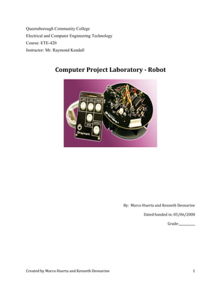
- 1. Queensborough Community College Electrical and Computer Engineering Technology Course: ETE-420 Instructor: Mr. Raymond Kendall Computer Project Laboratory - Robot By: Marco Huerta and Kenneth Deonarine Dated handed in: 05/06/2008 Grade:___________ Created by Marco Huerta and Kenneth Deonarine 1
- 2. Robot #1: Power Supply Quantity Measured value volts Expected (Calc.) value volt Percentage difference % VC 8.82V 9V 2% VB 5.65V 5.6V 0.17% VE 4.96V 5V 0.8% Expected Values VVVVVV VVV VVinV BEZE ZB C 56.06.5 6.5 9 =−=== == == Percentage difference %8.%100| 5 596.4 | %17.0%100| 6.5 6.559.5 | %2%100| 9 982.8 | %100||% =× − = =× − = =× − = × − = E B C V V V calac calcmeas diff Created by Marco Huerta and Kenneth Deonarine 2
- 3. Robot #2: LED Driver Circuit Quantity Measured value volts Expected (Calc.) value volt Percentage difference % VC 0.99V 1.2V 17.5% VB 0.72V 0.6V 20% VE 0V --- --- VV VVVV VLEDV B C BC 6.0 2.16.08.1 = =−= −= %20%100| 6.0 6.072.0 | %5.17%100| 2.1 2.199.0 | %100||% =× − = =× − = × − = B C V V calac calcmeas diff Created by Marco Huerta and Kenneth Deonarine 3
- 4. Robot #3: Audio Oscillator, Speaker Driver, and Control circuitry Timing Waveform Created by Marco Huerta and Kenneth Deonarine 4
- 5. Robot #3 Continued: Quiescent State Bias Voltages Quantity Measured Value Volts Calculated value Volts Percentage Difference % TR4 - VC 0 V 0 V --- TR4 - VB 0.04 V 0V --- TR4 - VE 0.62 V .6V 3.3% TR2 - VC 5.08 V 5 V 1.6% Audio Oscillator Pulse Repetition Rate Quantity Measured Value pps Calculated value pps Percentage Difference % PPR 2500 pps 2506 pps 0.23% Quiescent State Bias Voltages %6.1%100| 5 508.5 |% 52 %3.3%100| 6.0 6.062.0 |% 6.0V4 E =× − = =− =× − = =− diff VVTR diff VTR C Audio Oscillator Pulse Repetition Rate Total Period Pulse Repetition Rate ST pfKT CRT µ399 )330068(78.1 )912(78.1 = ×= ×= %23.0%100 2506 25062500 % %100% 2506 399 11 =× − = × − = === diff calc calcmeas diff pps ST PRR µ Created by Marco Huerta and Kenneth Deonarine 5
- 6. Robot #4: Motor Driver Circuit Left Motor VCE (TR6) VB (TR6) Volts VB (TR5) Volts Motor On 0.7 V 0.83V 1.60 V Motor Off 3.02 V --- --- Right Motor VCE (TR7) VB (TR7) Volts VB (TR9) Volts Motor On 0.7V 0.82V 1.59 V Motor Off 3.02V --- --- Comments The motion of the robot is controlled because 5V is applied from J2 to pin 12 and pin 14 on the 5501 socket (U6). For the right motor to function properly a positive voltage must go through R29 for TR8 to turn on. Then the voltage is applied through the base of TR7 and the left motor starts to work. The same is done for the right motor expect voltage goesthroughTR5 and TR6. Created by Marco Huerta and Kenneth Deonarine 6
- 7. Robot #5: Reset Circuit Programmed Reset Circuit Measurements Quantity Measured value µS Calculated value µS Percentage difference % TReset 250 µS 220.5 µS 13.4% Calculation ST pfkT CRT set set set µ5.220 )6800)(51(636.0 636.0 Re Re 63Re = Ω= = Percentage difference %4.13%100| 5.220 5.220250 | %100||% Re =× − = × − = setT calac calcmeas diff Created by Marco Huerta and Kenneth Deonarine 7
- 8. Robot #6: System Clock (Oscillator) System Clock (Oscillator) Pulse Repetition Rate Quantity Measured Value pps Calculated value pps Percentage difference % PPR 2.32 pps 2.19 pps 5.93% Measured pps msmsPWPW PRR msPW msPW LOHI LO HI 32.2 190240 11 190 240 = + = + = = = Calculation pps msms PRR msfKKkPW msfKKkPW LO HI 19.2 45.11045.345 1 45.11047.0)152200( 45.34547.0)15220500( = + = =×++= =×++= µ µ %93.5%100| 19.2 19.232.2 |% =× − =diff Created by Marco Huerta and Kenneth Deonarine 8
- 9. Robot #7: Memory Load Sequencer Created by Marco Huerta and Kenneth Deonarine 9
- 10. Robot #8: Keypad and Interface Circuitry Created by Marco Huerta and Kenneth Deonarine 10
- 11. Robot #9: Write Control Logic Write Control Pulse Width Measured value µS Calculated value µS Percentage difference % 220 µS 220.5 µS .23 % Calculated Pulse Width Pulse width = 0.636*R6*C5 = 220.5 µS Percent difference %100||% × − = calac calcmeas diff %23.%100| 5.220 5.220220 |% =× − =diff Created by Marco Huerta and Kenneth Deonarine 11
- 12. Robot #10: Address Counter Time Duration Measured value s Calculated value s Percentage difference % 120 sec 102sec 17.6 % Calculated sec PRR = 4Hz Time Duration TD =256 / PRR =256/2500= 102sec Percent Difference = %6.17%100| 102 102120 |% =× − =diff %100||% × − = calac calcmeas diff Created by Marco Huerta and Kenneth Deonarine 12
- 13. Robot #11: Memory Circuit Created by Marco Huerta and Kenneth Deonarine 13
- 14. Created by Marco Huerta and Kenneth Deonarine 14
- 15. Conclusion Of Robot Project In ET 420 Computer Project Laboratory Robot Project we constructed the Model 603A Digital Programmable Robot kit by Graymark. We built the various circuits; Power Supply, LED Driver Circuit, Audio Oscillator, Speaker Driver, and Control circuitry, Motor Driver Circuit, Reset Circuit, System Clock (Oscillator), Memory Load Sequencer, Keypad and Interface Circuitry, Write Control Logic, Address Counter, Memory Circuit by soldering the various components to the pre- made circuit board and assembled the mechanical parts of cogs, wheels, motors etc. We were able to successfully build our robot and make the speaker and motors work by using the remote control to issue commands such as beeping the speaker and right and left movements. We encountered a problem when we assembled the left motor cog not making contact with the other cogs that spun the left wheel. In order to compensate for this problem, we added two additional metal washers under the two rear motor circuit board connections points, this raised the back of the motor causing better cog contact with the left wheel assembly cogs. Another problem we had was current not getting to the motor to spin the wheels, we bypassed the current directly to the motors to verify the motors were working, verified the 2 AA batteries were good and then troubleshoot the battery holder. We discovered one of the battery holder leads was poorly constructed (not our lead to battery holder contact soldering), and replaced the battery holder, re-assembled the robot and the motors/wheels now responded to our remote control commands. We worked well as a team and our timely final results were proof of that partnership. Created by Marco Huerta and Kenneth Deonarine 15