1. 1/4 parapaw@iit.edu , bhujrah@iit.edu
Introduction
IEEE 802.16 - d is a standard for Wireless MAN.
The objective is to develop interfaces that should
allow service providers to deploy wireless solutions
to access systems based on Digital Subscriber Line
(DSL), cable and eventually optical fibers. Thus
BWA will have same kind of standards as DOCSIS
(Data over Cable Service Interface Specifications)
provides for cable modems.
802.16 - d have standards for PHY and MAC of
systems in 10 – 66 GHz bands. This region is
known LMDS (Local Multipoint Distribution
System). This distribution system is characterized
by very high data rates and quite short range due
to rain and foliage attenuation. IEEE 802.16a
standard supports operation in the 2 – 11 GHz
band that requires techniques that efficiently
diminishes the impairments of fading and multipath.
(Fading occurs due to different kind of attenuations
in the environment. Multipath problem occurs when
bits arrive with different delays because of different
paths). We will further deal with Wireless MAN –
OFDMA.
Overview of OFDM
As in European standard for Digital Video
Broadcasting – Terrestrial (DVB-T), 802.16 also
uses Coded OFDM (COFDM). This form of
multiplexing has an advantage over the single
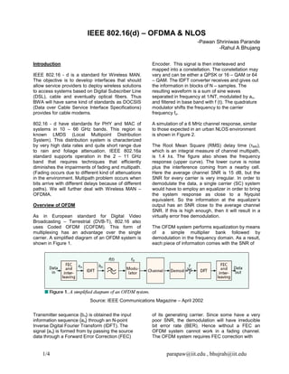
carrier. A simplified diagram of an OFDM system is
shown in Figure 1.
Encoder. This signal is then interleaved and
mapped into a constellation. The constellation may
vary and can be either a QPSK or 16 – QAM or 64
– QAM. The IDFT converter receives and gives out
the information in blocks of N – samples. The
resulting waveform is a sum of sine waves
separated in frequency at 1/NT, modulated by an,
and filtered in base band with f (t). The quadrature
modulator shifts the frequency to the carrier
frequency fo.
A simulation of a 6 MHz channel response, similar
to those expected in an urban NLOS environment
is shown in Figure 2.
The Root Mean Square (RMS) delay time (ÿMS),
which is an integral measure of channel multipath,
is 1.4 s. The figure also shows the frequency
response (upper curve). The lower curve is noise
plus the interference coming from a nearby cell.
Here the average channel SNR is 15 dB, but the
SNR for every carrier is very irregular. In order to
demodulate the data, a single carrier (SC) system
would have to employ an equalizer in order to bring
the system response as close to a Nyquist
equivalent. So the information at the equalizer’s
output has an SNR close to the average channel
SNR. If this is high enough, then it will result in a
virtually error free demodulation.
The OFDM system performs equalization by means
of a simple multiplier bank followed by
demodulation in the frequency domain. As a result,
each piece of information comes with the SNR of
Source: IEEE Communications Magazine – April 2002
Transmitter sequence {bn} is obtained the input
information sequence {an} through an N-point
Inverse Digital Fourier Transform (IDFT). The
signal {an} is formed from by passing the source
data through a Forward Error Correction (FEC)
of its generating carrier. Since some have a very
poor SNR, the demodulation will have irreducible
bit error rate (BER). Hence without a FEC an
OFDM system cannot work in a fading channel.
The OFDM system requires FEC correction with
IEEE 802.16(d) – OFDMA & NLOS
-Pawan Shriniwas Parande
-Rahul A Bhujang
2. 2/4 parapaw@iit.edu , bhujrah@iit.edu
frequency domain interleaving in order to scatter
the low SNR information.
The advantage of OFDM in selective fading
channels exists in the relative ease of frequency
domain separation of the noisy information from the
“clean” ones and its subsequent beneficial use with
error correction codes. This is the main reason for
the adoption of COFDM in 802.16.
Modes of Transmission
IEEE 802.16 has two flavors of OFDM systems:
one is OFDM and the other is OFDMA. OFDM is
used for less challenging applications and quite
short distances for indoors. It uses FFT (Fast
Fourier Transforms) with 256 carriers. Here all
carriers are transmitted at once. The downstream
data is time division multiplexed (TDM) whereas
the upstream uses TDMA.
OFDMA uses FFT having 2048 and 4096 carriers.
Here the higher FFT space is divided into sub
channels. They are used in downstream for
separating the data into logical streams. Those
streams employ different modulation, coding and
amplitude to suit the subscriber’s needs using
different channel characteristics.
The subscribers are assigned sub channels
through Media Access Protocol messages that are
sent on downstream. The sub channels are a
subset of carriers out of the total set of available
carriers. In order to lessen the frequency selective
fading, the carriers of one sub channel are spread
along the channel spectrum. Figure 3 shows the
sub channels in OFDMA.
Source: IEEE Communications Magazine – April
2002
Here the usable carrier space is divided into NG
successive groups. Each group further contains NE
successive carriers after excluding the initially
assigned pilots. So in essence the principle of
OFDMA consists of different users sharing the
upstream FFT space, while each transmits on one
or more sub channels.
A low upstream data rate is due to asymmetrical
traffic where the streams from each subscriber add
up in a multipoint – to – point form, while in the
downstream all the sub channels are transmitted
together. High consumers of upstream bandwidth
are allocated more than one sub channel. Hence
OFDMA allows a fine discretion in bandwidth
allocation that is consistent with the needs of most
Source: IEEE Communications Magazine – April 2002
3. 3/4 parapaw@iit.edu , bhujrah@iit.edu
subscribers. Interference is taken care of by using
Frequency Hopping Spread Spectrum (FHSS) in
the sub channels. The data from carriers with low
SNR are corrected through interleaving and coding.
There is no upstream interference within the cell
since its sub channels are orthogonal.
NLOS Operation
A customer can install the BWSU (Broadband
Wireless Subscriber Unit) on an internal house wall
or on the desktop and then sign on for the service
with the local provider. Some customers cannot
install antennas on masts as they do not have
access to roof tops or yards. These scenarios lead
to Non Line of Sight operation and extend then
amount of channel impairments, multipath fading
and path loss range. OFDMA provides some
mechanisms to lessen those impairments. They are
as follows.
Power Concentration In Sub Channels
An additional path loss of around 12 – 17 dB
occurs due to building penetration. This affects the
upstream transmission since the BWSU has low
transmission power due to limitations of cost and
safety. The use of sub channels partially
compensates for this imbalance by providing a 15
dB advantage for the upstream.
Space Diversity & STC
To enhance the upstream performance, a common
base station configuration employs two diversity
antennas for the upstream receiver with two
parallel FFT processors having a common clock.
The Maximal Ratio Receiver Combining (MRRC)
algorithm is performed on each carrier
independently using its channel and noise
estimations. For perfectly decorrelated diversity
antennas in Rayleigh channel, the MRRC can bring
upto10 dB of improvement in Eb / No ratio. For the
downstream, the use of two receiver BWSU
antennas is not practical because of cost, size and
esthetics problems. Separation between the
diversity antennas is necessary to achieve the
desired decorrelation. A separation of 10 (1.2 m at
2.5 GHz) is sufficient to bring significant diversity
gain. This takes care of the systems involving
indoor BWSUs that experience intense scattering.
Coding & Modulation Schemes
Different coding and modulation schemes are
allocated selectively to each subscriber in both
upstream and downstream. The trade – offs are
between throughput and robustness with an Eb / No
span of 15 dB. Subscribers in difficult terrains go in
for robust schemes with low throughput. Those in
better positions employ higher throughput schemes
and are able to transmit the same amount of data in
shorter allocations.
Same Frequency Networks
Same frequency networks (SFN) were one of the
main issues that promoted the adoption of OFDM for
BWA. The principle of SFN states that it is more
efficient to cover a geographical region with a
network of several low power and low height
transmitters than with one powerful transmitter on a
high tower. The multiple transmitters are
synchronized and transmit the same signal in the
same frequency. A single – carrier system will thus
receive the signal from multiple sources with different
delays. This results in long delay spread – 3.3 µs for
every kilometer – that is difficult to equalize. But
OFDM deals with this problem by feeding the
received signal, whose response has deep nulls and
peaks that the demodulator can separate, to the
correct CSI and in turn to the FEC decoder.
Modulation Schemes
The inter cell interference depends on propagation
conditions such as terrain, foliage, buildings, type and
height of base station antennas, subscriber antennas
and the nature of their installation. In the upstream,
the BWSU transmission power is adjusted according
to the path loss from its base station to create the
reference level in the base station receiver. In BWA
the subscribers are considered to be fixed and they
employ directive antennas. This limits the number of
BWSU’s that actually interfere with a nearby cell.
Environment and esthetics restrict subscriber
antenna sizes and the resulting directivity.
Source: IEEE Communications Magazine – April
2002
Figure 4 shows three modulation schemes QPSK, 16
– QAM and 64 – QAM. The trade – off in assigning a
particular modulation scheme is between robustness
of the channel and the desired throughput.
4. 4/4 parapaw@iit.edu , bhujrah@iit.edu
The optimal strategy is to assign the schemes with
their carrier to interference ratio (C / I) in the
reverse relation to their path loss. So higher C / I
schemes are assigned to BWSU’s in locations with
lower path loss (generally those closer to the base
station).
As the distance from the base station increases,
the channels need to become more robust in terms
of bit-error-rate performance, resistance to
multipath fading and sensitivity to timing and phase
errors. 64 – QAM fares better in combating
selective fading but on the other hand 16 – QAM
and QPSK, that have reduced bandwidth, have
lower bit error rates and are less sensitive to
synchronization errors. Hence channels employing
QPSK are more robust than the ones employing 16
– QAM, which are in turn more robust than the
channels employing 64 – QAM modulation scheme.
From the table in Figure 4, we can see that the
carrier to interference ratio (C / I) for 64 – QAM is
the largest and for QPSK is the smallest. Highest
bandwidth is provided by 64 – QAM technique. At
the cell extremities, we generally deal with data
from carriers with low SNR and low bandwidth.
The low bandwidth signals do not undergo flat
fading since its carriers are spread across the
entire channel bandwidth. Processing Gain (GP) is
the parameter that characterizes the degree of
spreading in a spread spectrum system. The table
shows that the value of GP, thus, is the highest for
QPSK and lowest for 64 – QAM.
Conclusion
The OFDMA technique is the best suited answer
for IEEE 802.16’s challenges, resulting from the
requirements of a solid, reliable and competitive
business. It can take on a wide variety of scenarios,
including urban and long range ones, involving long
delay spread. OFDMA provides a fine granulation
of bandwidth allocation and low BWSU
transmission power requirement for the upstream.
It also constitutes a spread spectrum environment,
where interference of low bit rate channels
averages over the entire bandwidth. The
assignment of various modulation schemes to sub
channels or BWSUs are used to optimize cell
capacity. Finally the principle of SFN brings in a
different strategy for BWA systems coverage under
OFDM technique.
References
1. BWA Solutions Based On OFDM Access in IEEE
802.16.
Israel Koffman & Vincentzio Roman – IEEE
Communications Magazine: April 2002
2. Comparative study of modulation techniques for
microwave digital radios
E Carpine, N A D’Andrea, U Mengali & G Russo
– Telettra SpA, Vimercate, Italy.