UT: A Review Of New Techniques
•
3 likes•3,000 views

In this article from the January 2015 World Pipelines edition, Andre Lamarre, Business Development Manager - Power Generation and Pipeline Markets at Olympus NDT, writes about trusted UT inspection methods and new technique developments used to contribute to pipeline integrity. More on Olympus ultrasonic flaw detectors: http://bit.ly/1zy3QUu Contact us: http://bit.ly/1rDmq94 Sign up for our newsletter: http://bit.ly/1j5FOTy

Recommended
Recommended
More Related Content
What's hot
What's hot (20)
Viewers also liked
Viewers also liked (12)
Similar to UT: A Review Of New Techniques
Similar to UT: A Review Of New Techniques (20)
More from Olympus IMS
More from Olympus IMS (20)
Recently uploaded
Recently uploaded (20)
UT: A Review Of New Techniques
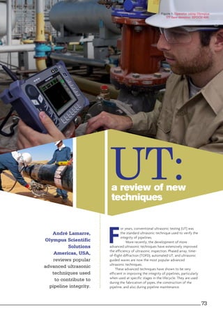
- 1. a review of new techniques UT: F or years, conventional ultrasonic testing (UT) was the standard ultrasonic technique used to verify the integrity of pipelines. More recently, the development of more advanced ultrasonic techniques have extensively improved the efficiency of ultrasonic inspection. Phased array, time- of-flight diffraction (TOFD), automated UT, and ultrasonic guided waves are now the most popular advanced ultrasonic techniques. These advanced techniques have shown to be very efficient in improving the integrity of pipelines, particularly when used at specific stages in the lifecycle. They are used during the fabrication of pipes, the construction of the pipeline, and also during pipeline maintenance. André Lamarre, Olympus Scientific Solutions Americas, USA, reviews popular advanced ultrasonic techniques used to contribute to pipeline integrity. Figure 1. Operator using Olympus UT flaw detector: EPOCH 600. 73
- 2. Advanced ultrasonic techniques Conventional ultrasonic testing usually consists of a UT flaw detector connected to an ultrasonic probe, which is manipulated by a skilled operator. The operator interprets an A-scan signal that represents the echo from reflectors in the part. Conventional UT permits detection and characterisation of flaws, but it is known to be slow and highly operator dependent. It is also limited in that there is no possibility to archive the data. Phased array technology Phased array technology is based on the capacity to electronically modify ultrasonic beams generated by probes that contain multiple small elements. When these elements are excited using different time delays (focal laws), the beam is steered at different angles and focused at different depths. If a long probe is used, the beam can also be multiplexed along the length of the probe, which simulates a mechanical movement. Phased array instruments have the capability to control the probe and the results are displayed in a comprehensive manner using images such as S-scan, B-scan and A-scan plots. Phased array instruments are available as portable, stand-alone instruments or PC-based instruments, each offering different electronic capabilities. Phased array technology increases the inspected volume coverage and the flaw detection capability through its multi-angled beam control capacity and comprehensive imaging. Time-of-flight diffraction Time-of-flight diffraction (TOFD) is an ultrasonic technique that relies on the property of defects, such as cracks, to diffract energy when the tip is impinged by an ultrasonic beam. Two ultrasonic transducers, one emitter and one receiver work in tandem to inspect the volume of a weld. When a crack is present in the weld, its tips diffract waves back to the receiver and, using simple trigonometry, the depth of the crack is defined. The use of the B-scan facilitates the interpretation of the signal and increases the probability of flaw detection. Automated ultrasonic testing Automated ultrasonic testing (AUT) uses powered scanners to move and record the position of ultrasonic probes. Different types of scanners can be adapted to perform applications such as girth weld inspection, heat exchanger inspection, etc. Manually driven scanners can be used for semi-automated ultrasonic testing at a reduced cost. Different inspection techniques, including conventional UT, phased array and TOFD, can be used for AUT. When used in combination they can improve the AUT speed, speed up the process of inspection, increase the repeatability and reduce the uncertainties induced by human operation. AUT can be used onsite to inspect a girth weld, or in a factory to verify the integrity of manufactured parts, such as pipes. When integrated into the production process, AUT is referred to an ultrasonic system. Guided wave technology Guided wave technology is used to locate potential degradation such as internal or external corrosion and metal loss in pipe. While conventional UT provides localised inspection underneath or in the vicinity of the sensor location, ultrasonic guided waves are able to screen the entire pipe wall, over tens of metres, from a single inspection position. The inspection can be done without removing insulation from the pipe. Advanced ultrasonics for pipe fabrication The fabrication of pipes used for pipelines is regimented by international standards (including the API 5L specification and DNV standards), which define the level of integrity required for pipes for specific applications. Since pipelines are subjected to constant pressure and a failure could result in catastrophe, a high level of quality is required. Advanced ultrasonic systems allow the manufacturer to Figure 3. Time-of-flight-diffraction principle of operation. Figure 2. Olympus ultrasonic portable phased-array instruments: OmniScan MX2 (left); OmniScan SX (right). 74 World Pipelines / DECEMBER 2014
- 3. meet these strict standards while maintaining a high rate of productivity. For example, industrial systems using phased-array techniques are used to perform full-body inspection of seamless and welded pipes. Fully automated and composed of a series of phased array probes, industrial systems can inspect carbon steel and high-alloyed steel pipes. Linear flaws as well as volumetric defects can be detected. Wall thickness variation and measurement of eccentricity are performed simultaneously. In such industrial environments, robust and powerful electronics are required. Also, the use of water wedges enables immersion of the pipe to ensure proper coupling of the phased array probes. Advanced ultrasonic testing during pipeline construction The quality of the welds between two sections of pipe is critical to ensuring the integrity of a pipeline. Automated ultrasonic testing that combines phased array and TOFD permits a reliable inspection of the girth welds and provides multiple advantages over radiography. To be able to withstand harsh environments, such as Middle-Eastern deserts and Siberian steppes, the automated system has to be designed and packaged to resist over- heating, rain, snow, sand, dust, etc. This automated ultrasonic in situ system consists of a pair of phased array probes, which generate multiple beams to cover specific zones of the weld and a pair of TOFD probes for volumetric inspection, mounted on a fully automated scanner. The weld is inspected in its entirety in only one pass, and the results are immediately shown on-screen. Inspectors benefit from comprehensive strip chart imaging to provide quick assessment of the quality of the weld. A major advantage that AUT has over radiography is its capability to measure the height and depth of an indication. When the height and depth of the indication is known, the critical length of a flaw for the engineering critical assessment (ECA) can be relaxed, resulting in less need for weld repair. This has been shown to generate important savings for pipeline contractors. In addition, AUT does not require the use of chemicals nor proximity to radiation. AUT inspection is also faster than radiography. Ultrasonic guided wave testing during pipeline maintenance Guided wave technology is used to screen in-service pipes and pipelines over long distances in order to localise areas of concern. Typically, a collar with low frequency (10 - 100 kHz) probes is installed around a pipe. Excited by a portable electronic unit, these transmit ultrasonic guided waves inside the pipe wall. While travelling in the pipe, any change of acoustic impedance due to wall reduction, corrosion, or geometry will reflect energy back to the transducers. The results are displayed using comprehensive imaging, such as F-scan, C-scan, and A-scan plots, which provides the means to identifying and localising areas of concerns. Figure 4. Ultrasonic guided waves beam propagation principle. Figure 6. Olympus PipeWizard in operation. Figure 5. Zoom on the water wedges assemble of the Olympus full-body inspection system. Figure 7. Olympus guided wave system: UltraWave LRT. DECEMBER 2014 / World Pipelines 75
- 4. This technique helps to reduce operating costs when inspecting pipes with limited access. It is recognised as a reliable screening method. In-depth evaluation of the area of concern is then carried out using other techniques such as ultrasonic phased array. Phased array ultrasonic testing during pipeline maintenance To maintain the integrity of a pipeline during its lifecycle, a maintenance programme is put in place to monitor degradation. Corrosion is considered as the main source of pipeline deterioration. Corrosion evaluation of a pipeline is performed in the ditch by a crew of operators. For the sake of practicality, portable battery-operated phased array instruments are used. Using a long phased array probe mounted on a water wedge, large areas can be inspected very quickly with an automated or semi-automated scanner. Mapping of the inspected area is displayed on the instrument, showing the remaining wall values in a colour-coded image known as C-scan. Conclusion Advanced ultrasonic techniques contribute significantly to the integrity of pipelines. When used during the fabrication of pipe, and the construction or maintenance of pipelines, these techniques optimise the accuracy, speed and reliability of ultrasonic inspection. The accurate and comprehensive images used by phased array, TOFD, automated UT, and guided wave technology offer considerable advantages for the interpretation of the inspection results. In addition, these techniques have shown to be reliable replacements for radiography in ensuring pipeline integrity. Note: this article is based on a paper presented at Pipeline Technology Conference 2014, Berlin, Germany. Figure 8. Olympus OmniScan MX2 ultrasonic phased-array unit with ChainScanner and Hydroform in operation for corrosion inspection.