SlideShare a Scribd company logo
1 of 28
Download to read offline
164_LOESCHEMillsfororesandminerals_EN500PicturesoriginatedattheelectronmicroscopelaboratoryofBauhaus-UniversitätWeimar
09/2012PrintedinGermany
Phosphate Rock, RSA Colemanite, Turkey Aragonite, Italy
Bronite, USA Phosphate Rock under direct light
microscope
Banded Iron Ore Formation, Brazil
Chalcopyrite, Chile 50 µm Stranskiite, Namibia 50 µm Apatite, RSA 20 µm
Titanium Slag, RSA 50 µm Baryte, Germany 20 µm Expanded Clay, Germany 50 µm
Clay, Germany 2 µm Dolomite, Russia 10 µm Bentonite, Libya 10 µm
Apatite Phlogopite
Si-Ca-Ti-OXide
Tremolite
DiposideDiposide
LOESCHE-MILLS
FOR ORES AND MINERALS
Loesche technology – always one step ahead
2
The company Loesche has more than 100 years of experience
in the comminution of coal, cement raw material, clinker, slag
and minerals. With consistently new developments, Loesche is
always one step ahead.
Since 1961 Loesche mills have been successfully used in the
ore industry.
1961 Delivery of the first mill for phosphate rock,
LM 12.20, Japan
1967 Commissioning of a Loesche mill, LM 12/850, for
comminution of magnesite, Mitsuhahmi, Japan
1973 Delivery of the first Loesche mill for comminution of
manganese dioxide, LM 9/760, Thessaloniki, Greece
1976 First use of a Loesche mill for comminution of baryte,
LM 14/1120, Ijmuiden, Netherlands
1987 Installation of a Loesche mill for comminution of lithium
feldspar, LM 13.2, Bikita, Zimbabwe
1993 Delivery of the first Loesche mill for comminution of
copper matte, LM 31.2, Magna, USA
1993 Delivery of a Loesche overflow mill for titanium slag,
LM 13.2, Vredenburg, RSA
1998 Installation of up to that point the largest Loesche mill
for comminution of phosphate rock, LM 50.4, Phalabora,
RSA
1999 Delivery of a Loesche mill for the test facility of Anglo
Research for comminution of different ore types, LM 3.6,
Johannesburg, RSA
2001 Delivery of a Loesche overflow mill for comminution of
titanium slag, LM 13.2, Empagnini, RSA
2006 Commissioning of a Loesche mill for comminution of
colemanite, LM 19.
Loesche Mill Type LM 60.4, Ras al Khaima,
United Arab Emirates, 2006
3
Loesche grinding technology is a dry milling process which
offers significant advantages over conventional crushing and
grinding technologies in ore beneficiation
• Low specific energy consumption
• Steep product particle size curve
• Reduced product overgrinding
• In-bed comminution
• Selective comminution
• Higher degree of liberation of the valuable minerals
• Combining of the crushing and grinding process stages
• Rapid response to changes in the feed composition
• Optimisation of throughput through online monitoring
• The grinding product has a positive effect on the down-
stream processes
• Compact design
Loesche grinding technology is particularly suitable for users:
• who aim to increase their recovery of respective ores and
minerals by applying the Loesche grinding technology
• who must reduce their operating costs
• who are dependent on a limited or expensive energy supply
• who operate or are planning ore processing in arid regions
• who operate obsolete or inefficient grinding systems
• whose processing plants no longer comply with the ecologi-
cal requirements
• whose space requirement for the building of complete
plants or modernisation of plant parts is limited
Loesche Mill Type LM 46.4, Lengerich, Germany, 2003
Loesche Mill Type LM 60.4, Ras al Khaima, United Arab Emirates, 2006
Principle of operation
4
Loesche grinding technologies allow users to choose different
comminution principles. The spectrum ranges from a combina-
tion of compressive and shear stress right through to shear-free
grinding, or pure compressive comminution.
The grinding material is comminuted in the Loesche mill
between the rotating grinding track and the stationary grinding
rollers.
There are two basic types of roller axis position in relation to the
centre of rotation of the grinding plate. This gives rise to differ-
ent comminution effects:
• Compressive comminution with shear component
• Pure compressive comminution.
Generally speaking, Loesche mills operate with a compressive
comminution system with a shear component. This effect is cre-
ated by tapered rollers, whose axes are angled below 15° with
respect to the horizontal grinding track. The roller axes do not
intersect the centre of rotation of the grinding plate. With pure
compressive comminution, the introduction of shear forces is
deliberately avoided.
This is achieved by tapered rollers, whose axes are angled in
relation to the horizontal grinding track in such a way that the
roller axis intersects exactly the centre of rotation of the grinding
plate with its axis.
The different comminution principles are matched to the
respective ore characteristics in order to achieve optimum
mineral liberation.
If an ore reacts positively to shear stress, a combination of com-
pressive and shear is used.
The Loesche patented shear-free grinding is used where pure
compressive comminution is desired. Through the use of shear-
free grinding the percent-age of finest grain can be additionally
reduced with regard to the already steep product particle size
curve. At the same time the percentage of medium grain size
fractions is increased. Further positive effects are additional
energy savings and the minimisation of wear.
The grinding product altered by shear-free grinding can reduce
the amount of fines up to 50 % and thereby result in significant
advantages for the downstream sorting processes.
α´α
5
100
90
80
70
60
50
40
30
20
10
0
1 10 100 1000
particle size [µm]
Accumulatedscreenunderflow[weight%]
Compressive and shear stress
Comparison of the Loesche comminution principles
Shear-free grinding
Advantages of the Loesche grinding process
for ore beneficiation
6
Grinding is of central importance to the downstream sorting pro-
cesses. The more complete the mineral liberation of the ground
ore, the greater the chances of obtaining a good recovery.
The Loesche grinding principle is based on in-bed comminution.
Due to the fact that the particles have many points of contact
with each other, the grinding force is directed through the grind-
ing bed. This results in a better degree of liberation compared
with conventional grinding technologies. Online monitoring of the
operating pressure of the grinding rollers and thus of the grinding
forces provides a controllable and consistent product fineness.
Monitoring of the grinding forces in combination with in-bed
comminution provides a selective ore comminution.
Direct classifying after each grinding contact helps to avoid
unwanted overgrinding and to achieve a steep product particle
size curve. In addition to the energy benefits, this has above all
positive effects on the downstream sorting processes.
With a maximum feed grain size of 150 mm and grinding prod-
ucts up to P80 of 20 µm, the Loesche mill combines the crushing
and grinding process stages in a single aggregate. Accordingly,
the Loesche mill can, depending on process management,
substitute two to three crushing and grinding stages. As well
as simplifying process management, the compact design of
Loesche grinding technology reduces the “plant footprint”.
In this way, the Loesche mill can be easily planned for incorpo-
ration in existing plant concepts or, in the case of new planning
concepts, can reduce the amount of surface area used.
100
90
80
70
60
50
40
30
20
10
0
100 1000
Particle size distribution of a Loesche Mill compared to a Ball Mill
Accumulativescreenthroughput[weight%]
Particle size [µm]
Ball Mill
Loesche Mill
F
F
FF
F
7
70
60
50
40
30
20
10
0
< 38 38 53 75 106
Degree of liberation
Optimum flotation range
Degreeofliberation[%]
Particle size µm]
Zn ore
(as example)
• SAG +
Ball Mill
• Loesche Mill
The advantages of the Loesche grinding process over conven-
tional grinding systems can be summarised as follows:
• Controlled grinding; thus specific liberation of
the valuable mineral
• Selective comminution by means of in-bed
comminution
• Minimisation of product overgrinding
• steeper product particle size curve
– minimises the amount of finest grain
– minimises the amount of coarse grain
– thus improved fine-tuning of downstream sorting
processes possible
• Higher degree of liberation
• Dry grinding product improves metering and conditioning of
the following downstream process stages
• Activation of particle surfaces
Advantages for the downstream process
The use of Loesche grinding technology delivers not only
advantages in the grinding process but also in the downstream
ore-sorting processes. These advantages can be put down to
the grinding characteristics of the Loesche mill and thus the
optimised grinding product.
Flotation
• Flotation kinetics is improved through the grinding products
• The recovery can be increased thanks to the improved
liberation of the valuable mineral
• Improved grade recovery relation
• The flotation times can be reduced, while
recovery remains the same
• Energy savings of up to 45% can be achieved compared
with conventional crushing and grinding circuits
• The operating costs are reduced by savings on
personnel, energy and grinding auxiliaries
• Reduction of specific wear
• Use in arid or permafrost regions is possible
• Water consumption is reduced
• The Loesche grinding process is self-regulating such that
the mill always runs at its optimum operating point
• Improvement in the environmental balance sheet thanks
to conservation of resources
• Reduced consumption of flotation reagent
thanks to low fines
• Dry grinding product provides for precise metering and
conditioning
• Reduced mineral surface lining by finest grain and thus
improved collector absorption
8
Density sorting:
• Improved recovery thanks to a better degree of liberation
at coarser feed size
• Improved concentrate grade thanks to a reduced amount
of finest particles in the feed
Heap and agitator leaching:
• Improved ore leaching solution contact thanks to higher
liberation of valuable material and thus increased recovery
• Improved leaching solution flow through the heap by
reduced amount of fineness
• Improved leaching kinetics
Magnetic separation:
• Higher recovery thanks to coarser feed size
• Reduced losses of valuable mineral in the finest
particle fraction
Water management
• Reduced water consumption
• Reduced problem of slimes during filtration
• Improved recovery of process water thanks
to reduced water absorption at the slimes and
faster sedimentation of the tailings
Grade recovery curve
Concentrate grade [g/t]
Recovery
[%]
Loesche Mill
Ball Mill
10 20[min 30t1
t2
t´1
t´2
Flotation kineticsRecovery
[%]
Retention time [min]; t
Ball Mill
Loesche Mill
9
Loesche Overflow Mill Type LM 13.2 SP, Namakwa Sands, South Africa, 1993
Customer benefit and customer satisfaction
10
Quality and reliability from the outset are the internationally
recognised advantages of Loesche grinding plants. Ever since
1928, when the Loesche mill was first introduced to the market,
the principle of the vertical roller mill with rotating grinding track
and individually guided rollers has proven to be particularly
energy- and resource-conserving.
These advantages of the Loesche mill are becoming increas-
ingly more important in the face of increasing plant sizes and
commitment to more economical use of resources, such as
energy, water, etc.
Furthermore, because of the high product rates for Loesche
mills the investment costs are significantly lower compared to
smaller grinding plants.
From sales through to aftersales service, from project planning
on schedule through to the handover of plants, Loesche is a
competent partner to its customers. Our maxim is:
“Every Loesche grinding plant is a reference plant!”
The cornerstones of our competence include:
• Customised plant concepts from planning through to com-
missioning, based on our own knowledge and experience,
paired with customer requirements
• Individual problem solutions with optimised process
technology
• Close cooperation with suppliers of further processing
equipment according to customer requirements
• Customer service: plant optimisations and advice on new
technical developments
• Long-term commitment to deliver spare parts
• Certification to EN ISO 9001: 2008.
Central grinding plant for granulated blast furnance slag, Loesche Mill Type LM 35 2+2, Rouen, France, 2003
11
Loesche Mill Type LM 69.6 under construction, Idhan, UAE, 2009
Layout and function of the Loesche mill
12
Layout
The established basic principle of the modular system patented
in 1970 is used for Loesche mills with two, three, four and six
roller modules. Each roller module consists of the grinding roller,
a rocker arm that transmits force to the roller by hydraulic spring
loading, and the upper end of which the rocker arm is supported
so that it can pivot. Large or small modules can be used in dif-
ferent numbers (two, three, four and six) in identical mill sizes
(grinding table diameter). In this way, customer-specific require-
ments can be satisfied on a customised basis.
Loesche technology is characterised by the following features:
• Each roller is held by a locally secured rocker arm.
• The roller-bearing-mounted rocker arm roller system is sup-
ported and guided precisely in a pedestal with integrated
spring assembly.
• The facility to raise the rollers serves as a starting aid for
the mill during startup with the grinding track filled. It is an
integral part of the hydropneumatic spring assembly.
• In each case two opposing rollers are connected to a com-
mon hydraulic unit (except on 3-roller mills).
• A virtually parallel grinding gap is maintained for the entire
service life of the grinding parts between the grinding rollers
and the grinding plates of the grinding table.
• Via the hydraulic system the grinding force can be optimised
in correspondence with the characteristics of the comminut-
ing ores.
Mill function, airflow mode
The ore raw material is fed via an air lock 1
1110
2
12
3
13
4
14
5
15
6
16
7
17
8
18
9
19
20 21 22 23 24 25 26 27 28
and falls via the
chute1
1110
2
12
3
13
4
14
5
15
6
16
7
17
8
18
9
19
20 21 22 23 24 25 26 27 28
onto the centre of the grinding tabel1
1110
2
12
3
13
4
14
5
15
6
16
7
17
8
18
9
19
20 21 22 23 24 25 26 27 28
. Free ferrous
foreign objects are separated out from the feed material mag-
netically before reaching the air lock 1
1110
2
12
3
13
4
14
5
15
6
16
7
17
8
18
9
19
20 21 22 23 24 25 26 27 28
and removed via a
diverter gate. A metal detector operates in a similar way and
ensures the separation of non-magnetic metal parts. The mate-
rial to be ground moves on the grinding track towards the edge
of the grinding table under the effect of centrifugal force and in
this way passes under the hydropneumatically spring-loaded
grinding rollers1
1110
2
12
3
13
4
14
5
15
6
16
7
17
8
18
9
19
20 21 22 23 24 25 26 27 28
. The material that has been drawn in is
ground in the material bed in the gap between the rollers and
grinding track. The rollers1
1110
2
12
3
13
4
14
5
15
6
16
7
17
8
18
9
19
20 21 22 23 24 25 26 27 28
are displaced upwards as they roll
over the material bed1
1110
2
12
3
13
4
14
5
15
6
16
7
17
8
18
9
19
20 21 22 23 24 25 26 27 28
. As a result the functional unit consist-
ing of rocker arm1
1110
2
12
3
13
4
14
5
15
6
16
7
17
8
18
9
19
20 21 22 23 24 25 26 27 28
, spring rod and pistons from the hydraulic
cylinder1
1110
2
12
3
13
4
14
5
15
6
16
7
17
8
18
9
19
20 21 22 23 24 25 26 27 28
are moved. The piston displaces the hydraulic oil
from the cylinder into the gas-filled bladder accumulator unit.
Nitrogen-filled rubber bladders in the accumulator units are
compressed and act as gas springs. The gas springs can be set
to be harder or softer by selecting the gas pressure in relation to
the hydraulic operating pressure, depending on the fracture
behaviour of the material to be ground.
The ground material is subjected to centrifugal force and rotates
outwards and over the edge of the grinding table. In the area of
the louvre ring1
1110
2
12
3
13
4
14
5
15
6
16
7
17
8
18
9
19
20 21 22 23 24 25 26 27 28
which surrounds the grinding table1
1110
2
12
3
13
4
14
5
15
6
16
7
17
8
20 21 22 23 24 25 26 27
the
stream of hot gas1
1110
2
12
3
13
4
14
5
15
6
16
7
17
8
18
9
19
20 21 22 23 24 25 26 27 28
directed upwards captures the mixture of
ground material and material as yet not completely ground and
conveys this to the classifier
1
1110
2
12
3
13
4
14
5
15
6
16
7
17
8
18
9
19
20 21 22 23 24 25 26 27 28
.
Depending on settings of the classifier
1
1110
2
12
3
13
4
14
5
15
6
16
7
17
8
18
9
19
20 21 22 23 24 25 26 27 28
it rejects coarse
materials. This falls into the internal grit return cone
1
1110
2
12
3
13
4
14
5
15
6
16
7
17
8
20 21 22 23 24 25 26 27
and then
onto the grinding table1
1110
2
12
3
13
4
14
5
15
6
16
7
17
8
18
9
19
20 21 22 23 24 25 26 27 28
for regrinding.
The ground material passes from the classifier and is conveyed
from the Loesche mill with the gas stream
1
1110
2
12
3
13
4
14
5
15
6
16
7
17
8
18
9
19
20 21 22 23 24 25 26 27 28
.
Foreign matter and small amounts of coarse material fall
through the louvre ring1
1110
2
12
3
13
4
14
5
15
6
16
7
17
8
18
9
19
20 21 22 23 24 25 26 27 28
into the ring channel
1
1110
2
12
3
13
4
14
5
15
6
16
7
17
8
18
9
19
20 21 22 23 24 25 26 27 28
as reject
material. Scrapers
1
1110
2
12
3
13
4
14
5
15
6
16
7
17
8
18
9
19
20 21 22 23 24 25 26 27 28
connected to the grinding table transport
foreign matter into the reject chute
1
1110
2
12
3
13
4
14
5
15
6
16
7
17
8
18
9
19
20 21 22 23 24 25 26 27 28
.
1
1110
2
12
3
13
4
14
5
15
6
16
7
17
8
18
9
19
20 21 22 23 24 25 26 27 28
1
1110
2
12
3
13
4
14
5
15
6
16
7
17
8
18
9
19
20 21 22 23 24 25 26 27 28
1
1110
2
12
3
13
4
14
5
15
6
16
7
17
8
18
9
19
20 21 22 23 24 25 26 27 28
1
1110
2
12
3
13
4
14
5
15
6
16
7
17
8
18
9
19
20 21 22 23 24 25 26 27 28
1
1110
2
12
3
13
4
14
5
15
6
16
7
17
8
18
9
19
20 21 22 23 24 25 26 27 28
1
1110
2
12
3
13
4
14
5
15
6
16
7
17
8
18
9
19
20 21 22 23 24 25 26 27 28
1
1110
2
12
3
13
4
14
5
15
6
16
7
17
8
18
9
19
20 21 22 23 24 25 26 27 28
1
1110
2
12
3
13
4
14
5
15
6
16
7
17
8
18
9
19
20 21 22 23 24 25 26 27 28
1
1110
2
12
3
13
4
14
5
15
6
16
7
17
8
18
9
19
20 21 22 23 24 25 26 27 28
1
1110
2
12
3
13
4
14
5
15
6
16
7
17
8
18
9
19
20 21 22 23 24 25 26 27 28
1
1110
2
12
3
13
4
14
5
15
6
16
7
17
8
18
9
19
20 21 22 23 24 25 26 27 28
1
1110
2
12
3
13
4
14
5
15
6
16
7
17
8
18
9
19
20 21 22 23 24 25 26 27 28
1
1110
2
12
3
13
4
14
5
15
6
16
7
17
8
18
9
19
20 21 22 23 24 25 26 27 28
1
1110
2
12
3
13
4
14
5
15
6
16
7
17
8
18
9
19
20 21 22 23 24 25 26 27 28
1
1110
2
12
3
13
4
14
5
15
6
16
7
17
8
18
9
19
20 21 22 23 24 25 26 27 28
1
1110
2
12
3
13
4
14
5
15
6
16
7
17
8
18
9
19
20 21 22 23 24 25 26 27 28
1
1110
2
12
3
13
4
14
5
15
6
16
7
17
8
18
9
19
20 21 22 23 24 25 26 27 28
1
1110
2
12
3
13
4
14
5
15
6
16
7
17
8
18
9
19
20 21 22 23 24 25 26 27 28
14
The grinding table is driven by an electric motor
1
1110
2
12
3
13
4
14
5
15
6
16
7
17
8
18
9
19
20 21 22 23 24 25 26 27 28
via an elas-
tic coupling
1
1110
2
12
3
13
4
14
5
15
6
16
7
17
8
18
9
19
20 21 22 23 24 25 26 27 28
and the mill gearbox with vertical output
1
1110
2
12
3
13
4
14
5
15
6
16
7
17
8
18
9
19
20 21 22 23 24 25 26 27 28
. A
segmental thrust bearing at the top of the gearbox absorbs the
grinding forces.
Before the mill motor is started, the grinding rollers1
1110
2
12
3
13
4
14
5
15
6
16
7
17
8
18
9
19
20 21 22 23 24 25 26 27 28
are
lifted hydraulically from the grinding track. The mill can then be
started at low starting torque not only empty, but also partially
filled. The grinding parts are prevented from coming into metal-
lic contact when the mill is empty or loaded by automatic lifting
of the rollers via a level control.
A so-called “auxiliary drive” for starting up a filled mill at low
revolutions is not necessary!
Mill function, overflow mode
In the case of ores with specific grinding characteristics or
coarse comminution, it might be beneficial to separate the
grinding and classifying processes. Overflow mode is selected
for such materials.
In contrast to airflow mode, classifying in overflow mode takes
place not in the classifier directly above the grinding chamber,
but in an external classifier. The material is transported via
corresponding conveying routes from the mill to the external
classifier.
The material ground by the grinding rollers is conveyed
by the centrifugal forces of the rotating grinding table over the
dam ring into the ring duct. As a result of the high circulation
of material it is discharged from the ring duct not by means of
a scraper, but instead in a free material flow via sloping chutes.
Maintenance
Worn grinding parts, tires and grinding track segments can be
easily and quickly changed.
The rollers are retracted out of the grinding chamber into a
vertical position with a swinging-out cylinder. Complete rollers,
tires and grinding plates are thus made accessible for lifting
gear.
During grinding the grinding parts wear out for the most part
over the entire service life to such a uniform extent that mill
throughput decreases only when the grinding parts are com-
pletely worn. Partial wear can be compensated for by specific
lining in the mill. This can be realised by removal of the grinding
parts or insitu by means of a special welding unit.
Loesche has the necessary expertise for welding insitu with
appropriate welding apparatus.
Hardfacing the grinding tire inside the mill Service drive
Combined drying and grinding and classifying
15
Combined drying and grinding
Ore raw material may be obtained with different moisture
contents as a result of the upstream separation processes.
However, when compared with a moist product, a dry grinding
product allows for more exact metering and conditioning to the
downstream sorting process.
Hot gases are supplied to the combined drying and grinding
process to evaporate the material moisture. Hot gases can
either be used from on site sources or by using the Loesche hot
gas generator.
As soon as the ground material leaves the table for the area
above the louvre ring, the water contained in the feed material
evaporates spontaneously on contact with the hot-gas flow.
Classifying
Depending on the application, Loesche vertical roller grinding
mills can be operated in so-called airflow or overflow mode.
In both modes direct classifying after the grinding process elimi-
nates the risk of product overgrinding.
Airflow mode combines the functions of grinding and classify-
ing in one aggregate. The air flow uplifts the material from the
grinding chamber to the classifier. In the classifier above the
grinding chamber the material ground to spec is separated
from the coarse particles (grit), which can drop back onto the
grinding table to be comminuted again or can be removed for
further treatment.
In overflow mode the ground material is discharged over the
edge of the grinding table and classified in an external process.
The grit is fed back into the grinding chamber. By isolating the
classifying process from the grinding process, it is possible
to provide for several classifying or sorting stages in order to
recover intermediate products.
Dynamic Loesche classifier (LSKS)
The Loesche LSKS-type caged-rotor classifier operates with
highly selective separation. It produces grain distributions of
both narrow and wide bandwidths. By varying the process-
technology setting parameters and thanks to appropriate built-
in classifier components, it is possible to satisfy these differing
demands made of the grain structure.
The gas/particle flow rising from the mills is directed via a static
guide vane assembly1
1110
2
12
3
13
4
14
5
15
6
16
7
17
8
18
9
19
20 21 22 23 24 25 26 27 28
to the classifying chamber. The gas/
solid-matter mixture flows, depending on the flap position, spe-
cifically into the space between the guide vane assembly1
1110
2
12
3
13
4
14
5
15
6
16
7
17
8
18
9
19
20 21 22 23 24 25 26 27 28
and
the concentric-running rotor with blades1
1110
2
12
3
13
4
14
5
15
6
16
7
17
8
18
9
19
20 21 22 23 24 25 26 27 28
.
As it rotates, the rotor accelerates the supplied gas/solid-matter
mixture tangentially. The centrifugal force generated in the pro-
cess rejects oversized grain.
The rotor speed and the gas flow with its flow direction deter-
mine the desired separation diameter. This can be adjusted
within wide limits.
A unique feature of this classifier type is the continuous reclas-
sifying of the particle flows rejected by the rotor. When they fly
outwards under centrifugal force in the annular gap, they are
blasted again by the gas flow directed upwards/inwards. Here
agglomerated particles dissolve in such a way that they follow
the product flow as individual grains and do not drop as appa-
rent oversized grains with the grit back onto the grinding table.
Layout:
1
1110
2
12
3
13
4
14
5
15
6
16
7
17
8
18
9
19
20 21 22 23 24 25 26 27 28
Grit cone
1
1110
2
12
3
13
4
14
5
15
6
16
7
17
8
18
9
19
20 21 22 23 24 25 26 27 28
Guide vane assembly
1
1110
2
12
3
13
4
14
5
15
6
16
7
17
8
18
9
19
20 21 22 23 24 25 26 27 28
Rotor with blades
1
1110
2
12
3
13
4
14
5
15
6
16
7
17
8
18
9
19
20 21 22 23 24 25 26 27 28
Rotor shaft
1
1110
2
12
3
13
4
14
5
15
6
16
7
17
8
18
9
19
20 21 22 23 24 25 26 27 28
Housing
1
1110
2
12
3
13
4
14
5
15
6
16
7
17
8
18
9
19
20 21 22 23 24 25 26 27 28
Material feed chute
1
1110
2
12
3
13
4
14
5
15
6
16
7
17
8
18
9
19
20 21 22 23 24 25 26 27 28
Product discharge
1
1110
2
12
3
13
4
14
5
15
6
16
7
17
8
18
9
1
20 21 22 23 24 25 26 27 28
1
1110
2
12
3
13
4
14
5
15
6
16
7
17
8
18
9
19
20 21 22 23 24 25 26 27 281
1110
2
12
3
13
4
14
5
15
6
16
7
17
8
18
9
19
20 21 22 23 24 25 26 27 28
1
1110
2
12
3
13
4
14
5
15
6
16
7
17
8
1
20 21 22 23 24 25 26 27 21
1110
2
12
3
13
4
14
5
15
6
16
7
17
8
18
9
19
20 21 22 23 24 25 26 27 28
1
1110
2
12
3
13
4
14
5
15
6
16
7
17
8
18
9
20 21 22 23 24 25 26 27 28
1
1110
2
12
3
13
4
14
5
15
6
16
7
17
8
18
9
19
20 21 22 23 24 25 26 27 28
Sizing – model series – drives
16
Dimensioning parameters
The following standard parameters are decisive in the sizing of
Loesche mills:
• GRINDING PRESSURE
This lies between the minimum value for solid fuels and the
maximum value for ores.
• MATERIAL MOISTURE
The Loesche mill can process material with moisture of up
to 25%.
• PRODUCT FINENESS
In the case of air-classifying it is possible, depending on the
customer requirement, to create product fineness figures of
P80 of 500 μm to P80 of 20 μm.
• DRIVE POWER
The specific energy consumption during the grinding test is
decisive for gearbox and motor power.
In the development history of Loesche mills the sizes have
been adapted to the constant demand for higher capacity and
throughput figures. The modular construction of the mills also
enables customer-specific solutions to be realised by combin-
ing standard components.
Model series
• The mill sizes are identified according to the outer effective
diameter of the grinding track in decimetres [dm].
• The identification is – separated by a point – followed by a
digit. This digit indicates the number of rollers operating in
the mill.
• Loesche mills are modular in design. The units of rollers,
rocker arms and rocker-related spring assembly compo-
nents with their pedestal are the modules. They are
arranged as required 2, 3, 4 and 6 times around a grinding
table.
• The number and size of the rollers is dependent on the
required product rate in conjunction with the “Loesche load
factor”, the product of the grindability, moisture and fine-
ness factors.
The required gas flow is decisive for sizing the housings of
the mill and the classifier.
17
Drives
An electric motor is used as the drive. It drives a planetary gear-
box with bevel gears. The input shaft is horizontal, the output
shaft operates vertically upwards. The drive is enclosed at the
top by a horizontal output flange. The gearbox contains a seg-
mental thrust bearing which absorbs the grinding forces in the
housing at the top. Loesche mill gearboxes are developed in
cooperation between Loesche GmbH and well-known gearbox
manufacturers. The field service conditions under which the
gearboxes must operate are matched to each other. Decades of
field experience with Loesche mills determine the design of the
(mill) gearboxes and their peripherals under all climatic condi-
tions.
Today’s modern gearboxes are, like Loesche mills, modular in
design. Torque split provides for a reduction of rotating masses
with simultaneous multiple use of engineering elements in gear-
boxes of different sizes and power outputs.
A lubrication unit ensures that the gear teeth, the shaft bearings
and the segmental thrust bearing are supplied with sufficient oil.
Filters and cooling systems condition the oil. Electrical and
hydraulic monitoring instruments incorporated in the PLC ensu-
re safe operation.
In accordance with today’s state-of-the technology the modular
construction principle of gearboxes allows further power incre-
ases without the need to develop a new construction concept.
The Loesche mill does not require a motor with increased star-
ting torque. Because the rollers are hydraulically raised, the
breakaway torque of the filled mill amounts to only 40% of the
full-load torque. A “standard motor” can easily deliver this star-
ting torque.
The installed motor power is geared towards the mill’s energy
demand and is determined in the Loesche technical centre duri-
ng the grinding test. The closest matching commercially availa-
ble motor is selected and recommended to the customer.
Loesche mill gearbox
Complete grinding plants
18
Complete grinding plants
An ore grinding plant is featured on the following page. Grinding
plants that use Loesche mills are characterised primarily by
their simple design and layout. A grinding plant consists of the
following process stages and components:
• Material feeding
• Grinding and classifying
• Reject/circulation handling
• Product separation
• Mill fan
• Hot gas generator (optional)
• Process/measuring and control technology
Complete grinding plants incorporate material storage hoppers
and conveyor systems suitable for the ore industry as well as
metering elements to the Loesche mill. Included downstream
of the classifying processes is a filter system, which features,
as well as the actual filter and the piping system, the product
dischargea and process-air circuit assemblies. The Loesche
grinding plant also features components for metal separation
and Loesche’s own hot gas generators for drying purposes, if
these are required for the process.
Material which has not yet attained the desired product particle
size is returned to the grinding process.
Final product is intermediately stored in the hopper and is for-
warded from there to the downstream processes.
Complete Loesche grinding plant with mill and filter
19
Overflow and airflow modes
The Loesche grinding plant is incorporated between the primary
crusher and the downstream process in an ore beneficiation
plant. There are essentially two different processes for commi-
nuting ores with the Loesche mill. The difference being whether
the recirculating load is conveyed in an internal or external
circuit.
When the ground ore leaves the grinding chamber after the
grinding process under its own gravitational force, this is known
as overflow mode. When the material is discharged by means of
an air flow via a classifier, this is known as airflow mode.
The choice of mode is determined by the properties of the
material and the objective of the grinding process.
Overflow mode
In the overflow mode the classification and grinding processes are
separate. The material is transported from the mill to the classifier
via appropriate conveying systems.
Prior to feeding the mill, the ore is classified in the pre-
classifying stage. Ore already according to spec is separated
in the pre-classifier and guided to the final classifying stage
the dynamic classifier. Thereby overgrinding and unnecessary
energy consumption are prevented. The coarse fractions of
the pre-classifier and the dynamic classifier are fed to the mill.
After the material has been ground it is discharged through the
ring duct and re-fed to the pre-classifier, thereby the grinding
classifying circuit is closed.
The final product of the dynamic classifier is separated
in the filter.
Airflow mode
In airflow mode grinding and classifying are combined in a single
machine (Loesche mill with classifier). Within the mill and to the
classifier the material is transported via airflow.
The feed material from the primary crushing stage is directed
after upstream metal separation into the grinding chamber of
the Loesche mill. The ground material is directed with the upris-
ing gas flow into the classifier. The grit drops back onto the
grinding table and is comminuted again. Product of sufficient
fineness passes the classifier and is separated in the filter.
In both processes the finished grinding product is finally
removed from the filters and fed to the downstream process via
a product buffer.
Both overflow and airflow modes are closed grinding/classify-
ing circuits. By constant separation of the final product from
the grinding process an overgrinding of the material can be
avoided.
Loesche overflow mill
22
Primary crushing stages
23
Loesche overflow mill
1 Feed, crushing plant
2 Conveyor belt, mill feed
3 Overbelt magnet
4 Metal detector
5 2-way chute
6 Defective material collector
7 Conveyor belt, classifier charge
8 Static classifier
9 Dynamic classifier
10 Conveyor belt
11 Loesche mill
12 Discharge system
13 Conveyor belt circulation
14 Filter system
15 Filter fan
16 Stack
17 Product discharge
18 Recirculation gas line
with dumper (optional)
19 Hot gas generator (optional)
20 Product storage
Loesche airflow mill
1 Feed, crushing plant
2 Conveyor belt, mill feed
3 Overbelt magnet
4 Metal detector
5 2-way chute
6 Defective material collector
7 Gate
8 Loesche mill
9 Reject system
10 Conveyor belt, reject system
11 Filter system
12 Filter fan
13 Stack
14 Product discharge
15 Recirculation gas line
with dumper (optional)
16 Hot gas generator (optional)
17 Product storage
Downstream
processes
Downstream
processes
1
1110
2
12
3
13
4
14
5
15
6
16
7
17
8
18
9
19
20 21 22 23 24 25 26 27 28
1
1110
2
12
3
13
4
14
5
15
6
16
7
17
8
18
9
19
20 21 22 23 24 25 26 27 28
1
1110
2
12
3
13
4
14
5
15
6
16
7
17
8
18
9
19
20 21 22 23 24 25 26 27 28
13
4
14
5
15
6
16
7
17
8
18
9
19
23 24 25 26 27 28
12
3
13
4
14
5
15
6
16
7
17
8
18
9
19
22 23 24 25 26 27 28
1
1110
2
12
3
13
4
14
5
15
6
16
7
17
8
18
9
19
20 21 22 23 24 25 26 27 28
1
1110
2
12
3
13
4
14
5
15
6
16
7
17
8
18
9
19
20 21 22 23 24 25 26 27 28
1
1110
2
12
3
13
4
14
5
15
6
16
7
17
8
18
9
19
20 21 22 23 24 25 26 27 28
1
1110
2
12
3
13
4
14
5
15
6
16
7
17
8
18
9
19
20 21 22 23 24 25 26 27 28
1
1110
2
12
3
13
4
14
5
15
6
16
7
17
8
18
9
19
20 21 22 23 24 25 26 27 28
Construction
1
1110
2
12
3
13
4
14
5
15
6
16
7
17
8
18
9
19
20 21 22 23 24 25 26 27 28
Burner
1
1110
2
12
3
13
4
14
5
15
6
16
7
17
8
18
9
19
20 21 22 23 24 25 26 27 28
Fuel
1
1110
2
12
3
13
4
14
5
15
6
16
7
17
8
18
9
19
20 21 22 23 24 25 26 27 28
Combustion air
1
1110
2
12
3
13
4
14
5
15
6
16
7
17
8
18
9
19
20 21 22 23 24 25 26 27 28
Burner muffle
1
1110
2
12
3
13
4
14
5
15
6
16
7
17
8
18
9
19
20 21 22 23 24 25 26 27 28
Spiral housing
1
1110
2
12
3
13
4
14
5
15
6
16
7
17
8
18
9
19
20 21 22 23 24 25 26 27 28
Perforated jacket
1
1110
2
12
3
13
4
14
5
15
6
16
7
17
8
18
9
19
20 21 22 23 24 25 26 27 28
Annular gap
1
1110
2
12
3
13
4
14
5
15
6
16
7
17
8
18
9
19
20 21 22 23 24 25 26 27 28
Protective casing
1
1110
2
12
3
13
4
14
5
15
6
16
7
17
8
18
9
19
20 21 22 23 24 25 26 27 28
Temperature control1
1110
2
12
3
13
4
14
5
15
6
16
7
17
8
18
9
19
20 21 22 23 24 25 26 27 28
Hot gas outlet
Loesche hot gas generator
24
The perforated jacket combustion system developed by
Loesche in the mid 1960’s consists of a combustion chamber of
heat resistant steel with burner muffle, and is well known in the
market under the name LOMA Hot Gas Generator. The LOMA
Hot Gas Generator has been used worldwide for decades in
many different types of thermal processes for optimization.
Design and operation:
• The combustion chamber consists of heat resistant steels –
no refractory brickwork is necessary
• When starting up the hot gas generator heat losses are
minimised since it is not necessary to heat up refractory
brickwork. A start at full load is therefore possible.
• Very good thermal shock resistance and rapid load changes
with only a short delay
• High cooling rate of the combustion chamber prevents ther-
mal overloading of following units.An EMERGENCY chimney
stack is not necessary in EMERGENCY-OFF SITUATIONS
and when starting and stopping.
• Accessible within a short time for inspection
• Low wear
• Short installation times, low weight, small space require-
ment. Can be installed in existing plants. Complete preas-
sembly is carried out – also for larger LOMA combustion
units.
Loesche hot gas generators are used where hot gases are
required for direct drying, e.g. in the cement, steel, industrial
minerals, ore, wood, cattle food, agri-food and chemical indu-
stries.
Mode of operation
The process gas stream which enters the spiral housing1
1110
2
12
3
13
4
14
5
15
6
16
7
17
8
18
9
19
20 21 22 23 24 25 26 27 28
cools
both the protective jacket housing1
1110
2
12
3
13
4
14
5
15
6
16
7
17
8
18
9
19
20 21 22 23 24 25 26 27 28
and the perforated jacket
1
1110
2
12
3
13
4
14
5
15
6
16
7
17
8
18
9
19
20 21 22 23 24 25 26 27 28
. as a result of the flow pattern. The process gas enters the
interior of the combustion chamber through the annular gap1
1110
2
12
3
13
4
14
5
15
6
16
7
17
8
18
9
19
20 21 22 23 24 25 26 27 28
and holes in the perforated jacket, and mixes there with the hot
flue gases from combustion. At the same time the flame and
hot flue gases are kept away from the perforated jacket.
Heating media
• Natural gas, bio gas, coke gas, blast furnace gas and other
low calorific value gases
• Light and heavy oils, wood and lignite dust
LOMA Hot Gas Generator units are constantly being developed
and conform to current technical standards. More than 600 hot
gas generators (of this type) have been commissioned for a heat
flow of between 100 kW and 64,000 kW.
LOMA combustion unit type
LF 25 with a natural gas burner, 2005
Loesche rotary vane feeder
25
Feeding of Loesche CS mills is carried out via a rotary vane
feeder in order to prevent false air ingress into the mill interior.
Material is fed continuously from above via the inlet hopper
into every vane pocket of the slowly rotating vane feeder.
In order to reduce wear from the abrasive feed stock the
peripheral speed is low and the filling level limited to 40%.
Adjustable sealing strips on the rotor prevent any large gaps
between the wearing plate of the housing and the rotor. The
material is discharged downwards into the feed chute of the
mill.
Hot gas can be passed through the inside of the rotary feeder to
prevent material caking. It is easy to dismantle for maintenance
purposes.
The Loesche test facility for raw materials testing,
Research and Development
Calibrated standard grinding tests for mill sizing
Loesche has many years of experience in designing grinding
mills. The most important prerequisite for correctly designed
grinding mills is an exact knowledge of the physical properties of
the materials to be ground.
The most important characteristic values of a material to be
ground are the Loesche grindability factor and the specific
power demand in relation to a defined fineness. Depending on
the geological formation of the material to be ground, materials
with highly different properties are found in nature, even with
materials which appear visually to be similar.
Three well equipped laboratory LM 3.6 grinding mills are avai-
lable in the Loesche test plant for performing standard grinding
tests.
Technological development through practical laboratory
grinding tests
One of the first steps in introducing new technologies is the
practical laboratory test.
Within the framework of our research and development projects
the following actions are carried out:
• New materials for grinding of future market requirements
are examined
• Optimised mill settings for special products are determined
• Plant components and process configurations are opti-
mised
• New wear materials and concepts are tested
Our test plant is constructed in such a way that various modes
of operation and plant process configurations can be simulated
in the tests.
Fully-automatic operation with PLC LM 3.6 laboratory mill
Analysis possibilities
• Pure density determination with gas pycnometer
• Determination of mass-related surface according to Blaine
• Grain size analysis with Cilas laser granulometer
• Sieve analyses with Alpine air-jet screening method
• Sieve analyses with Retsch vibrating sieves
• Grindability according to Hardgrove
• Grindability according to Zeisel
• Microscopy with Zeiss Stemi SV11
• Drying ovens for moisture determination
• Coal testing (Cfix, volatile matter, ash content)
26
Loesche – worldwide presence
Loesche is an export-oriented company run by the owner, which was established in 1906 in Berlin.
Today the company is internationally active with subsidiaries, representatives and agencies world-
wide.
Our engineers are constantly developing new ideas and individual concepts for grinding
technologies and preparation processes for the benefit of our customers. Their competence is
mainly due to our worldwide information management.
This ensures that current knowledge and developments can also be used immediately for our own
projects.
The services of our subsidiaries and agencies are of key importance for analysis, processing and
solving specific project problems for our customers.
Please visit our homepage at www.loesche.com
for up-to-date information on our overseas companies.

More Related Content

What's hot

Coal preparation Plant(www.lmmgroupcn.com)
Coal preparation Plant(www.lmmgroupcn.com)Coal preparation Plant(www.lmmgroupcn.com)
Coal preparation Plant(www.lmmgroupcn.com)LMM GROUP CO., LTD.
 
Report on the manufacturing process step
Report on the manufacturing process stepReport on the manufacturing process step
Report on the manufacturing process stepNur Natasya Umira
 
Bakri Final Presentation 2
Bakri Final Presentation  2Bakri Final Presentation  2
Bakri Final Presentation 2ahmadbakri991
 
Oilfield Chemical ppt one-to-use v2
Oilfield Chemical ppt one-to-use v2Oilfield Chemical ppt one-to-use v2
Oilfield Chemical ppt one-to-use v2David A. Berg
 
DRILLING FLUIDS FOR THE HPHT ENVIRONMENT
DRILLING FLUIDS FOR THE HPHT ENVIRONMENTDRILLING FLUIDS FOR THE HPHT ENVIRONMENT
DRILLING FLUIDS FOR THE HPHT ENVIRONMENTMohan Doshi
 
Aphron and synthetic muds
Aphron and synthetic mudsAphron and synthetic muds
Aphron and synthetic mudsHamza Mukhtar
 
Analysis of Various Cement grinding Systems with Respect to Power Consumption...
Analysis of Various Cement grinding Systems with Respect to Power Consumption...Analysis of Various Cement grinding Systems with Respect to Power Consumption...
Analysis of Various Cement grinding Systems with Respect to Power Consumption...Karan Walia
 
Drilling fluids
Drilling fluidsDrilling fluids
Drilling fluidsWajid09
 
Concrete Batching Plant Manufacturer - Nilkanth Engineering works
Concrete Batching Plant Manufacturer - Nilkanth Engineering worksConcrete Batching Plant Manufacturer - Nilkanth Engineering works
Concrete Batching Plant Manufacturer - Nilkanth Engineering worksNilkanth Engineering Works
 
RBB Pitch Bearing Reliability Presentation
RBB Pitch Bearing Reliability PresentationRBB Pitch Bearing Reliability Presentation
RBB Pitch Bearing Reliability PresentationRob Budny
 
Non damaging drilling fluids for oil and gas
Non damaging drilling fluids for oil and gasNon damaging drilling fluids for oil and gas
Non damaging drilling fluids for oil and gasSidharth Gautam
 
Creping. Tissue machine creping
Creping. Tissue machine crepingCreping. Tissue machine creping
Creping. Tissue machine crepingNelson Izaguirre
 
Drilling Fluids Mud
Drilling Fluids MudDrilling Fluids Mud
Drilling Fluids MudM.T.H Group
 
Drilling fluids trouble shooting
Drilling fluids trouble shooting  Drilling fluids trouble shooting
Drilling fluids trouble shooting Mohan Doshi
 

What's hot (20)

Coal preparation Plant(www.lmmgroupcn.com)
Coal preparation Plant(www.lmmgroupcn.com)Coal preparation Plant(www.lmmgroupcn.com)
Coal preparation Plant(www.lmmgroupcn.com)
 
Report on the manufacturing process step
Report on the manufacturing process stepReport on the manufacturing process step
Report on the manufacturing process step
 
Bakri Final Presentation 2
Bakri Final Presentation  2Bakri Final Presentation  2
Bakri Final Presentation 2
 
Drilling fluids
Drilling fluidsDrilling fluids
Drilling fluids
 
Block 6 SP 14
Block 6 SP 14Block 6 SP 14
Block 6 SP 14
 
Oilfield Chemical ppt one-to-use v2
Oilfield Chemical ppt one-to-use v2Oilfield Chemical ppt one-to-use v2
Oilfield Chemical ppt one-to-use v2
 
DRILLING FLUIDS FOR THE HPHT ENVIRONMENT
DRILLING FLUIDS FOR THE HPHT ENVIRONMENTDRILLING FLUIDS FOR THE HPHT ENVIRONMENT
DRILLING FLUIDS FOR THE HPHT ENVIRONMENT
 
Aphron and synthetic muds
Aphron and synthetic mudsAphron and synthetic muds
Aphron and synthetic muds
 
Analysis of Various Cement grinding Systems with Respect to Power Consumption...
Analysis of Various Cement grinding Systems with Respect to Power Consumption...Analysis of Various Cement grinding Systems with Respect to Power Consumption...
Analysis of Various Cement grinding Systems with Respect to Power Consumption...
 
Drilling fluids
Drilling fluidsDrilling fluids
Drilling fluids
 
Grinding Aids for Cement
Grinding Aids for CementGrinding Aids for Cement
Grinding Aids for Cement
 
Concrete Batching Plant Manufacturer - Nilkanth Engineering works
Concrete Batching Plant Manufacturer - Nilkanth Engineering worksConcrete Batching Plant Manufacturer - Nilkanth Engineering works
Concrete Batching Plant Manufacturer - Nilkanth Engineering works
 
RBB Pitch Bearing Reliability Presentation
RBB Pitch Bearing Reliability PresentationRBB Pitch Bearing Reliability Presentation
RBB Pitch Bearing Reliability Presentation
 
Drilling fluids
Drilling fluidsDrilling fluids
Drilling fluids
 
Non damaging drilling fluids for oil and gas
Non damaging drilling fluids for oil and gasNon damaging drilling fluids for oil and gas
Non damaging drilling fluids for oil and gas
 
Creping. Tissue machine creping
Creping. Tissue machine crepingCreping. Tissue machine creping
Creping. Tissue machine creping
 
DRILL BIT, DRILLING FLUIDS
DRILL BIT, DRILLING FLUIDSDRILL BIT, DRILLING FLUIDS
DRILL BIT, DRILLING FLUIDS
 
Drilling Fluids Mud
Drilling Fluids MudDrilling Fluids Mud
Drilling Fluids Mud
 
Drilling fluids trouble shooting
Drilling fluids trouble shooting  Drilling fluids trouble shooting
Drilling fluids trouble shooting
 
CASE STUDY OF WAKOTA BRIDGE
CASE STUDY OF WAKOTA BRIDGECASE STUDY OF WAKOTA BRIDGE
CASE STUDY OF WAKOTA BRIDGE
 

Viewers also liked

Selective Comminution of Concrete Waste and Recovery of the Concrete Constitu...
Selective Comminution of Concrete Waste and Recovery of the Concrete Constitu...Selective Comminution of Concrete Waste and Recovery of the Concrete Constitu...
Selective Comminution of Concrete Waste and Recovery of the Concrete Constitu...LOESCHE
 
LOESCHE: INSIGHT
LOESCHE: INSIGHTLOESCHE: INSIGHT
LOESCHE: INSIGHTLOESCHE
 
New Horizons: Loesche & A TEC GRECO
New Horizons: Loesche & A TEC GRECONew Horizons: Loesche & A TEC GRECO
New Horizons: Loesche & A TEC GRECOLOESCHE
 
Loesche Automation Technology
Loesche Automation TechnologyLoesche Automation Technology
Loesche Automation TechnologyLOESCHE
 
Efficient Grinding
Efficient GrindingEfficient Grinding
Efficient GrindingLOESCHE
 
A Peek at the Past: 100th Anniversary of Loesche
A Peek at the Past: 100th Anniversary of LoescheA Peek at the Past: 100th Anniversary of Loesche
A Peek at the Past: 100th Anniversary of LoescheLOESCHE
 
Two products from a single grinding mill
Two products from a single grinding millTwo products from a single grinding mill
Two products from a single grinding millLOESCHE
 
LOESCHE: OVERVIEW
LOESCHE: OVERVIEWLOESCHE: OVERVIEW
LOESCHE: OVERVIEWLOESCHE
 
IGCC Plant Taen Coal Korea
IGCC Plant Taen Coal KoreaIGCC Plant Taen Coal Korea
IGCC Plant Taen Coal KoreaLOESCHE
 
LM-Master for Vertical Roller Mills
LM-Master for Vertical Roller MillsLM-Master for Vertical Roller Mills
LM-Master for Vertical Roller MillsLOESCHE
 
aixergee - Process Optimization for the Cement Industry
aixergee - Process Optimization for the Cement Industryaixergee - Process Optimization for the Cement Industry
aixergee - Process Optimization for the Cement IndustryLOESCHE
 
Pénétrez Dans Une Nouvelle Dimension - CCG de LOESCHE
Pénétrez Dans Une Nouvelle Dimension - CCG de LOESCHEPénétrez Dans Une Nouvelle Dimension - CCG de LOESCHE
Pénétrez Dans Une Nouvelle Dimension - CCG de LOESCHELOESCHE
 
Drive Selection for Large LOESCHE Vertical Roller Mills
Drive Selection for Large LOESCHE Vertical Roller MillsDrive Selection for Large LOESCHE Vertical Roller Mills
Drive Selection for Large LOESCHE Vertical Roller MillsLOESCHE
 
Latest Technological Innovation in Grinding With the Vertical Roller Mill
Latest Technological Innovation in Grinding With the Vertical Roller MillLatest Technological Innovation in Grinding With the Vertical Roller Mill
Latest Technological Innovation in Grinding With the Vertical Roller MillLOESCHE
 

Viewers also liked (14)

Selective Comminution of Concrete Waste and Recovery of the Concrete Constitu...
Selective Comminution of Concrete Waste and Recovery of the Concrete Constitu...Selective Comminution of Concrete Waste and Recovery of the Concrete Constitu...
Selective Comminution of Concrete Waste and Recovery of the Concrete Constitu...
 
LOESCHE: INSIGHT
LOESCHE: INSIGHTLOESCHE: INSIGHT
LOESCHE: INSIGHT
 
New Horizons: Loesche & A TEC GRECO
New Horizons: Loesche & A TEC GRECONew Horizons: Loesche & A TEC GRECO
New Horizons: Loesche & A TEC GRECO
 
Loesche Automation Technology
Loesche Automation TechnologyLoesche Automation Technology
Loesche Automation Technology
 
Efficient Grinding
Efficient GrindingEfficient Grinding
Efficient Grinding
 
A Peek at the Past: 100th Anniversary of Loesche
A Peek at the Past: 100th Anniversary of LoescheA Peek at the Past: 100th Anniversary of Loesche
A Peek at the Past: 100th Anniversary of Loesche
 
Two products from a single grinding mill
Two products from a single grinding millTwo products from a single grinding mill
Two products from a single grinding mill
 
LOESCHE: OVERVIEW
LOESCHE: OVERVIEWLOESCHE: OVERVIEW
LOESCHE: OVERVIEW
 
IGCC Plant Taen Coal Korea
IGCC Plant Taen Coal KoreaIGCC Plant Taen Coal Korea
IGCC Plant Taen Coal Korea
 
LM-Master for Vertical Roller Mills
LM-Master for Vertical Roller MillsLM-Master for Vertical Roller Mills
LM-Master for Vertical Roller Mills
 
aixergee - Process Optimization for the Cement Industry
aixergee - Process Optimization for the Cement Industryaixergee - Process Optimization for the Cement Industry
aixergee - Process Optimization for the Cement Industry
 
Pénétrez Dans Une Nouvelle Dimension - CCG de LOESCHE
Pénétrez Dans Une Nouvelle Dimension - CCG de LOESCHEPénétrez Dans Une Nouvelle Dimension - CCG de LOESCHE
Pénétrez Dans Une Nouvelle Dimension - CCG de LOESCHE
 
Drive Selection for Large LOESCHE Vertical Roller Mills
Drive Selection for Large LOESCHE Vertical Roller MillsDrive Selection for Large LOESCHE Vertical Roller Mills
Drive Selection for Large LOESCHE Vertical Roller Mills
 
Latest Technological Innovation in Grinding With the Vertical Roller Mill
Latest Technological Innovation in Grinding With the Vertical Roller MillLatest Technological Innovation in Grinding With the Vertical Roller Mill
Latest Technological Innovation in Grinding With the Vertical Roller Mill
 

Similar to Loesche Mills for ores and mineral

Get Fit For The Future - Dry Ore Comminution Technology
Get Fit For The Future - Dry Ore Comminution TechnologyGet Fit For The Future - Dry Ore Comminution Technology
Get Fit For The Future - Dry Ore Comminution TechnologyLOESCHE
 
Impact crusher used in the coal industry
Impact crusher used in the coal industryImpact crusher used in the coal industry
Impact crusher used in the coal industrysmilewei005
 
ballmillinggrainsizeandmechanicalattrition.pptx
ballmillinggrainsizeandmechanicalattrition.pptxballmillinggrainsizeandmechanicalattrition.pptx
ballmillinggrainsizeandmechanicalattrition.pptxAditya Bhardwaj
 
Large scale manufacture of suspension
Large scale manufacture of suspensionLarge scale manufacture of suspension
Large scale manufacture of suspensionMirza Salman Baig
 
Chemical Industry Case Study: Dispersing Fumed Silica
Chemical Industry Case Study: Dispersing Fumed SilicaChemical Industry Case Study: Dispersing Fumed Silica
Chemical Industry Case Study: Dispersing Fumed SilicaMatt Smith
 
Drilling efficiency optimization at hassai site
Drilling efficiency optimization at hassai siteDrilling efficiency optimization at hassai site
Drilling efficiency optimization at hassai siteAhmad Elsir
 
LOESCHE Grinding Technology for the Power Industry
LOESCHE Grinding Technology for the Power IndustryLOESCHE Grinding Technology for the Power Industry
LOESCHE Grinding Technology for the Power IndustryLOESCHE
 
Propel industries private limited (3)
Propel industries private limited (3)Propel industries private limited (3)
Propel industries private limited (3)Vignesh Devi
 
PARTICLE SIZE REDUCTION TECHNIQUES
PARTICLE SIZE REDUCTION TECHNIQUESPARTICLE SIZE REDUCTION TECHNIQUES
PARTICLE SIZE REDUCTION TECHNIQUESSagar Savale
 
Tata steel west bokaro washery #3 report
Tata steel west bokaro washery #3 reportTata steel west bokaro washery #3 report
Tata steel west bokaro washery #3 reportSuchit Sharma
 
BM-Maintenance-Damia Cement.ppt
BM-Maintenance-Damia Cement.pptBM-Maintenance-Damia Cement.ppt
BM-Maintenance-Damia Cement.pptDinesh566323
 
Pharmaceutical Engineering: Size reduction
Pharmaceutical Engineering: Size reductionPharmaceutical Engineering: Size reduction
Pharmaceutical Engineering: Size reductionParag Jain
 
Large scale manufacture of suspension emulsion sb
Large scale manufacture of suspension emulsion sbLarge scale manufacture of suspension emulsion sb
Large scale manufacture of suspension emulsion sbMirza Salman Baig
 
Esite Raleigh Hall – Nortonin keraamisten hiomalaikkojen uusi tehdas
Esite Raleigh Hall – Nortonin keraamisten hiomalaikkojen uusi tehdasEsite Raleigh Hall – Nortonin keraamisten hiomalaikkojen uusi tehdas
Esite Raleigh Hall – Nortonin keraamisten hiomalaikkojen uusi tehdasSaint-Gobain Abrasives AB
 
Broschyr Raleigh Hall - Ny fabrik för Norton keramiska slipskivor
Broschyr Raleigh Hall - Ny fabrik för Norton keramiska slipskivorBroschyr Raleigh Hall - Ny fabrik för Norton keramiska slipskivor
Broschyr Raleigh Hall - Ny fabrik för Norton keramiska slipskivorSaint-Gobain Abrasives AB
 
Chemical Industry Case Study: High Speed Despersion of Titanium Dioxide
Chemical Industry Case Study: High Speed Despersion of Titanium DioxideChemical Industry Case Study: High Speed Despersion of Titanium Dioxide
Chemical Industry Case Study: High Speed Despersion of Titanium DioxideMatt Smith
 
Meeting the Market Demand for Greater Grinding Capacities
Meeting the Market Demand for Greater Grinding CapacitiesMeeting the Market Demand for Greater Grinding Capacities
Meeting the Market Demand for Greater Grinding CapacitiesLOESCHE
 

Similar to Loesche Mills for ores and mineral (20)

Get Fit For The Future - Dry Ore Comminution Technology
Get Fit For The Future - Dry Ore Comminution TechnologyGet Fit For The Future - Dry Ore Comminution Technology
Get Fit For The Future - Dry Ore Comminution Technology
 
Impact crusher used in the coal industry
Impact crusher used in the coal industryImpact crusher used in the coal industry
Impact crusher used in the coal industry
 
ballmillinggrainsizeandmechanicalattrition.pptx
ballmillinggrainsizeandmechanicalattrition.pptxballmillinggrainsizeandmechanicalattrition.pptx
ballmillinggrainsizeandmechanicalattrition.pptx
 
Large scale manufacture of suspension
Large scale manufacture of suspensionLarge scale manufacture of suspension
Large scale manufacture of suspension
 
Chemical Industry Case Study: Dispersing Fumed Silica
Chemical Industry Case Study: Dispersing Fumed SilicaChemical Industry Case Study: Dispersing Fumed Silica
Chemical Industry Case Study: Dispersing Fumed Silica
 
Drilling efficiency optimization at hassai site
Drilling efficiency optimization at hassai siteDrilling efficiency optimization at hassai site
Drilling efficiency optimization at hassai site
 
LOESCHE Grinding Technology for the Power Industry
LOESCHE Grinding Technology for the Power IndustryLOESCHE Grinding Technology for the Power Industry
LOESCHE Grinding Technology for the Power Industry
 
Propel industries private limited (3)
Propel industries private limited (3)Propel industries private limited (3)
Propel industries private limited (3)
 
PARTICLE SIZE REDUCTION TECHNIQUES
PARTICLE SIZE REDUCTION TECHNIQUESPARTICLE SIZE REDUCTION TECHNIQUES
PARTICLE SIZE REDUCTION TECHNIQUES
 
Tata steel west bokaro washery #3 report
Tata steel west bokaro washery #3 reportTata steel west bokaro washery #3 report
Tata steel west bokaro washery #3 report
 
BM-Maintenance-Damia Cement.ppt
BM-Maintenance-Damia Cement.pptBM-Maintenance-Damia Cement.ppt
BM-Maintenance-Damia Cement.ppt
 
CRUSHERS.pdf
CRUSHERS.pdfCRUSHERS.pdf
CRUSHERS.pdf
 
Pharmaceutical Engineering: Size reduction
Pharmaceutical Engineering: Size reductionPharmaceutical Engineering: Size reduction
Pharmaceutical Engineering: Size reduction
 
Large scale manufacture of suspension emulsion sb
Large scale manufacture of suspension emulsion sbLarge scale manufacture of suspension emulsion sb
Large scale manufacture of suspension emulsion sb
 
Esite Raleigh Hall – Nortonin keraamisten hiomalaikkojen uusi tehdas
Esite Raleigh Hall – Nortonin keraamisten hiomalaikkojen uusi tehdasEsite Raleigh Hall – Nortonin keraamisten hiomalaikkojen uusi tehdas
Esite Raleigh Hall – Nortonin keraamisten hiomalaikkojen uusi tehdas
 
Broschyr Raleigh Hall - Ny fabrik för Norton keramiska slipskivor
Broschyr Raleigh Hall - Ny fabrik för Norton keramiska slipskivorBroschyr Raleigh Hall - Ny fabrik för Norton keramiska slipskivor
Broschyr Raleigh Hall - Ny fabrik för Norton keramiska slipskivor
 
Brochure Raleigh Hall
Brochure Raleigh HallBrochure Raleigh Hall
Brochure Raleigh Hall
 
Mining applications
Mining applicationsMining applications
Mining applications
 
Chemical Industry Case Study: High Speed Despersion of Titanium Dioxide
Chemical Industry Case Study: High Speed Despersion of Titanium DioxideChemical Industry Case Study: High Speed Despersion of Titanium Dioxide
Chemical Industry Case Study: High Speed Despersion of Titanium Dioxide
 
Meeting the Market Demand for Greater Grinding Capacities
Meeting the Market Demand for Greater Grinding CapacitiesMeeting the Market Demand for Greater Grinding Capacities
Meeting the Market Demand for Greater Grinding Capacities
 

More from LOESCHE

Reshape Your CO2 Footprint With C/Clay
Reshape Your CO2 Footprint With C/ClayReshape Your CO2 Footprint With C/Clay
Reshape Your CO2 Footprint With C/ClayLOESCHE
 
Alternative Fuel Market After Covid-19 – Focus on Efficiency and Quality
Alternative Fuel Market After Covid-19 – Focus on Efficiency and QualityAlternative Fuel Market After Covid-19 – Focus on Efficiency and Quality
Alternative Fuel Market After Covid-19 – Focus on Efficiency and QualityLOESCHE
 
Setting a New Benchmark
Setting a New BenchmarkSetting a New Benchmark
Setting a New BenchmarkLOESCHE
 
Truck Unloading Station
Truck Unloading StationTruck Unloading Station
Truck Unloading StationLOESCHE
 
PlanEX Discharge System
PlanEX Discharge SystemPlanEX Discharge System
PlanEX Discharge SystemLOESCHE
 
BinEX Discharge System
BinEX Discharge SystemBinEX Discharge System
BinEX Discharge SystemLOESCHE
 
Bunker Discharge System
Bunker Discharge SystemBunker Discharge System
Bunker Discharge SystemLOESCHE
 
Dry Granulated BF Sand: A Groundbreaking and Sustainable Innovation
Dry Granulated BF Sand: A Groundbreaking and Sustainable InnovationDry Granulated BF Sand: A Groundbreaking and Sustainable Innovation
Dry Granulated BF Sand: A Groundbreaking and Sustainable InnovationLOESCHE
 
Loesche-Separation Plant for Production of Ultrafine Granulated Blastfurnace ...
Loesche-Separation Plant for Production of Ultrafine Granulated Blastfurnace ...Loesche-Separation Plant for Production of Ultrafine Granulated Blastfurnace ...
Loesche-Separation Plant for Production of Ultrafine Granulated Blastfurnace ...LOESCHE
 
LOESCHE Waste Conditioning
LOESCHE Waste ConditioningLOESCHE Waste Conditioning
LOESCHE Waste ConditioningLOESCHE
 
LOESCHE's Large Cement Mill 72.4+4 CS
LOESCHE's Large Cement Mill 72.4+4 CSLOESCHE's Large Cement Mill 72.4+4 CS
LOESCHE's Large Cement Mill 72.4+4 CSLOESCHE
 
Turning Waste Into Profit
Turning Waste Into ProfitTurning Waste Into Profit
Turning Waste Into ProfitLOESCHE
 
World Café @ LOESCHE Symposium Hanoi
World Café @ LOESCHE Symposium HanoiWorld Café @ LOESCHE Symposium Hanoi
World Café @ LOESCHE Symposium HanoiLOESCHE
 
An Integrated Approach to Alternative Fuel use in Cement Making
An Integrated Approach to Alternative Fuel use in Cement MakingAn Integrated Approach to Alternative Fuel use in Cement Making
An Integrated Approach to Alternative Fuel use in Cement MakingLOESCHE
 
LOESCHE’s Most Recent Step Into AF: Integration of MHC Technologies
LOESCHE’s Most Recent Step Into AF: Integration of MHC TechnologiesLOESCHE’s Most Recent Step Into AF: Integration of MHC Technologies
LOESCHE’s Most Recent Step Into AF: Integration of MHC TechnologiesLOESCHE
 
From Waste to a Reliable Co-Processing
From Waste to a Reliable Co-ProcessingFrom Waste to a Reliable Co-Processing
From Waste to a Reliable Co-ProcessingLOESCHE
 
LOESCHE Cement Mill LM 72.4+4 at Hub Cement Plant Pakistan
LOESCHE Cement Mill LM 72.4+4 at Hub Cement Plant PakistanLOESCHE Cement Mill LM 72.4+4 at Hub Cement Plant Pakistan
LOESCHE Cement Mill LM 72.4+4 at Hub Cement Plant PakistanLOESCHE
 
Optimal Alternative Fuel Burning Starts with Computer Simulation
Optimal Alternative Fuel Burning Starts with Computer SimulationOptimal Alternative Fuel Burning Starts with Computer Simulation
Optimal Alternative Fuel Burning Starts with Computer SimulationLOESCHE
 
State of the Art Waste Conditioning at LOESCHE
State of the Art Waste Conditioning at LOESCHEState of the Art Waste Conditioning at LOESCHE
State of the Art Waste Conditioning at LOESCHELOESCHE
 
Sep 2019
Sep 2019Sep 2019
Sep 2019LOESCHE
 

More from LOESCHE (20)

Reshape Your CO2 Footprint With C/Clay
Reshape Your CO2 Footprint With C/ClayReshape Your CO2 Footprint With C/Clay
Reshape Your CO2 Footprint With C/Clay
 
Alternative Fuel Market After Covid-19 – Focus on Efficiency and Quality
Alternative Fuel Market After Covid-19 – Focus on Efficiency and QualityAlternative Fuel Market After Covid-19 – Focus on Efficiency and Quality
Alternative Fuel Market After Covid-19 – Focus on Efficiency and Quality
 
Setting a New Benchmark
Setting a New BenchmarkSetting a New Benchmark
Setting a New Benchmark
 
Truck Unloading Station
Truck Unloading StationTruck Unloading Station
Truck Unloading Station
 
PlanEX Discharge System
PlanEX Discharge SystemPlanEX Discharge System
PlanEX Discharge System
 
BinEX Discharge System
BinEX Discharge SystemBinEX Discharge System
BinEX Discharge System
 
Bunker Discharge System
Bunker Discharge SystemBunker Discharge System
Bunker Discharge System
 
Dry Granulated BF Sand: A Groundbreaking and Sustainable Innovation
Dry Granulated BF Sand: A Groundbreaking and Sustainable InnovationDry Granulated BF Sand: A Groundbreaking and Sustainable Innovation
Dry Granulated BF Sand: A Groundbreaking and Sustainable Innovation
 
Loesche-Separation Plant for Production of Ultrafine Granulated Blastfurnace ...
Loesche-Separation Plant for Production of Ultrafine Granulated Blastfurnace ...Loesche-Separation Plant for Production of Ultrafine Granulated Blastfurnace ...
Loesche-Separation Plant for Production of Ultrafine Granulated Blastfurnace ...
 
LOESCHE Waste Conditioning
LOESCHE Waste ConditioningLOESCHE Waste Conditioning
LOESCHE Waste Conditioning
 
LOESCHE's Large Cement Mill 72.4+4 CS
LOESCHE's Large Cement Mill 72.4+4 CSLOESCHE's Large Cement Mill 72.4+4 CS
LOESCHE's Large Cement Mill 72.4+4 CS
 
Turning Waste Into Profit
Turning Waste Into ProfitTurning Waste Into Profit
Turning Waste Into Profit
 
World Café @ LOESCHE Symposium Hanoi
World Café @ LOESCHE Symposium HanoiWorld Café @ LOESCHE Symposium Hanoi
World Café @ LOESCHE Symposium Hanoi
 
An Integrated Approach to Alternative Fuel use in Cement Making
An Integrated Approach to Alternative Fuel use in Cement MakingAn Integrated Approach to Alternative Fuel use in Cement Making
An Integrated Approach to Alternative Fuel use in Cement Making
 
LOESCHE’s Most Recent Step Into AF: Integration of MHC Technologies
LOESCHE’s Most Recent Step Into AF: Integration of MHC TechnologiesLOESCHE’s Most Recent Step Into AF: Integration of MHC Technologies
LOESCHE’s Most Recent Step Into AF: Integration of MHC Technologies
 
From Waste to a Reliable Co-Processing
From Waste to a Reliable Co-ProcessingFrom Waste to a Reliable Co-Processing
From Waste to a Reliable Co-Processing
 
LOESCHE Cement Mill LM 72.4+4 at Hub Cement Plant Pakistan
LOESCHE Cement Mill LM 72.4+4 at Hub Cement Plant PakistanLOESCHE Cement Mill LM 72.4+4 at Hub Cement Plant Pakistan
LOESCHE Cement Mill LM 72.4+4 at Hub Cement Plant Pakistan
 
Optimal Alternative Fuel Burning Starts with Computer Simulation
Optimal Alternative Fuel Burning Starts with Computer SimulationOptimal Alternative Fuel Burning Starts with Computer Simulation
Optimal Alternative Fuel Burning Starts with Computer Simulation
 
State of the Art Waste Conditioning at LOESCHE
State of the Art Waste Conditioning at LOESCHEState of the Art Waste Conditioning at LOESCHE
State of the Art Waste Conditioning at LOESCHE
 
Sep 2019
Sep 2019Sep 2019
Sep 2019
 

Recently uploaded

Unleash Your Potential - Namagunga Girls Coding Club
Unleash Your Potential - Namagunga Girls Coding ClubUnleash Your Potential - Namagunga Girls Coding Club
Unleash Your Potential - Namagunga Girls Coding ClubKalema Edgar
 
What's New in Teams Calling, Meetings and Devices March 2024
What's New in Teams Calling, Meetings and Devices March 2024What's New in Teams Calling, Meetings and Devices March 2024
What's New in Teams Calling, Meetings and Devices March 2024Stephanie Beckett
 
"Debugging python applications inside k8s environment", Andrii Soldatenko
"Debugging python applications inside k8s environment", Andrii Soldatenko"Debugging python applications inside k8s environment", Andrii Soldatenko
"Debugging python applications inside k8s environment", Andrii SoldatenkoFwdays
 
Advanced Computer Architecture – An Introduction
Advanced Computer Architecture – An IntroductionAdvanced Computer Architecture – An Introduction
Advanced Computer Architecture – An IntroductionDilum Bandara
 
The Ultimate Guide to Choosing WordPress Pros and Cons
The Ultimate Guide to Choosing WordPress Pros and ConsThe Ultimate Guide to Choosing WordPress Pros and Cons
The Ultimate Guide to Choosing WordPress Pros and ConsPixlogix Infotech
 
From Family Reminiscence to Scholarly Archive .
From Family Reminiscence to Scholarly Archive .From Family Reminiscence to Scholarly Archive .
From Family Reminiscence to Scholarly Archive .Alan Dix
 
Story boards and shot lists for my a level piece
Story boards and shot lists for my a level pieceStory boards and shot lists for my a level piece
Story boards and shot lists for my a level piececharlottematthew16
 
Ensuring Technical Readiness For Copilot in Microsoft 365
Ensuring Technical Readiness For Copilot in Microsoft 365Ensuring Technical Readiness For Copilot in Microsoft 365
Ensuring Technical Readiness For Copilot in Microsoft 3652toLead Limited
 
Commit 2024 - Secret Management made easy
Commit 2024 - Secret Management made easyCommit 2024 - Secret Management made easy
Commit 2024 - Secret Management made easyAlfredo García Lavilla
 
Artificial intelligence in cctv survelliance.pptx
Artificial intelligence in cctv survelliance.pptxArtificial intelligence in cctv survelliance.pptx
Artificial intelligence in cctv survelliance.pptxhariprasad279825
 
SIP trunking in Janus @ Kamailio World 2024
SIP trunking in Janus @ Kamailio World 2024SIP trunking in Janus @ Kamailio World 2024
SIP trunking in Janus @ Kamailio World 2024Lorenzo Miniero
 
TrustArc Webinar - How to Build Consumer Trust Through Data Privacy
TrustArc Webinar - How to Build Consumer Trust Through Data PrivacyTrustArc Webinar - How to Build Consumer Trust Through Data Privacy
TrustArc Webinar - How to Build Consumer Trust Through Data PrivacyTrustArc
 
Connect Wave/ connectwave Pitch Deck Presentation
Connect Wave/ connectwave Pitch Deck PresentationConnect Wave/ connectwave Pitch Deck Presentation
Connect Wave/ connectwave Pitch Deck PresentationSlibray Presentation
 
Search Engine Optimization SEO PDF for 2024.pdf
Search Engine Optimization SEO PDF for 2024.pdfSearch Engine Optimization SEO PDF for 2024.pdf
Search Engine Optimization SEO PDF for 2024.pdfRankYa
 
Human Factors of XR: Using Human Factors to Design XR Systems
Human Factors of XR: Using Human Factors to Design XR SystemsHuman Factors of XR: Using Human Factors to Design XR Systems
Human Factors of XR: Using Human Factors to Design XR SystemsMark Billinghurst
 
Leverage Zilliz Serverless - Up to 50X Saving for Your Vector Storage Cost
Leverage Zilliz Serverless - Up to 50X Saving for Your Vector Storage CostLeverage Zilliz Serverless - Up to 50X Saving for Your Vector Storage Cost
Leverage Zilliz Serverless - Up to 50X Saving for Your Vector Storage CostZilliz
 
Tampa BSides - Chef's Tour of Microsoft Security Adoption Framework (SAF)
Tampa BSides - Chef's Tour of Microsoft Security Adoption Framework (SAF)Tampa BSides - Chef's Tour of Microsoft Security Adoption Framework (SAF)
Tampa BSides - Chef's Tour of Microsoft Security Adoption Framework (SAF)Mark Simos
 
Are Multi-Cloud and Serverless Good or Bad?
Are Multi-Cloud and Serverless Good or Bad?Are Multi-Cloud and Serverless Good or Bad?
Are Multi-Cloud and Serverless Good or Bad?Mattias Andersson
 
SAP Build Work Zone - Overview L2-L3.pptx
SAP Build Work Zone - Overview L2-L3.pptxSAP Build Work Zone - Overview L2-L3.pptx
SAP Build Work Zone - Overview L2-L3.pptxNavinnSomaal
 
Scanning the Internet for External Cloud Exposures via SSL Certs
Scanning the Internet for External Cloud Exposures via SSL CertsScanning the Internet for External Cloud Exposures via SSL Certs
Scanning the Internet for External Cloud Exposures via SSL CertsRizwan Syed
 

Recently uploaded (20)

Unleash Your Potential - Namagunga Girls Coding Club
Unleash Your Potential - Namagunga Girls Coding ClubUnleash Your Potential - Namagunga Girls Coding Club
Unleash Your Potential - Namagunga Girls Coding Club
 
What's New in Teams Calling, Meetings and Devices March 2024
What's New in Teams Calling, Meetings and Devices March 2024What's New in Teams Calling, Meetings and Devices March 2024
What's New in Teams Calling, Meetings and Devices March 2024
 
"Debugging python applications inside k8s environment", Andrii Soldatenko
"Debugging python applications inside k8s environment", Andrii Soldatenko"Debugging python applications inside k8s environment", Andrii Soldatenko
"Debugging python applications inside k8s environment", Andrii Soldatenko
 
Advanced Computer Architecture – An Introduction
Advanced Computer Architecture – An IntroductionAdvanced Computer Architecture – An Introduction
Advanced Computer Architecture – An Introduction
 
The Ultimate Guide to Choosing WordPress Pros and Cons
The Ultimate Guide to Choosing WordPress Pros and ConsThe Ultimate Guide to Choosing WordPress Pros and Cons
The Ultimate Guide to Choosing WordPress Pros and Cons
 
From Family Reminiscence to Scholarly Archive .
From Family Reminiscence to Scholarly Archive .From Family Reminiscence to Scholarly Archive .
From Family Reminiscence to Scholarly Archive .
 
Story boards and shot lists for my a level piece
Story boards and shot lists for my a level pieceStory boards and shot lists for my a level piece
Story boards and shot lists for my a level piece
 
Ensuring Technical Readiness For Copilot in Microsoft 365
Ensuring Technical Readiness For Copilot in Microsoft 365Ensuring Technical Readiness For Copilot in Microsoft 365
Ensuring Technical Readiness For Copilot in Microsoft 365
 
Commit 2024 - Secret Management made easy
Commit 2024 - Secret Management made easyCommit 2024 - Secret Management made easy
Commit 2024 - Secret Management made easy
 
Artificial intelligence in cctv survelliance.pptx
Artificial intelligence in cctv survelliance.pptxArtificial intelligence in cctv survelliance.pptx
Artificial intelligence in cctv survelliance.pptx
 
SIP trunking in Janus @ Kamailio World 2024
SIP trunking in Janus @ Kamailio World 2024SIP trunking in Janus @ Kamailio World 2024
SIP trunking in Janus @ Kamailio World 2024
 
TrustArc Webinar - How to Build Consumer Trust Through Data Privacy
TrustArc Webinar - How to Build Consumer Trust Through Data PrivacyTrustArc Webinar - How to Build Consumer Trust Through Data Privacy
TrustArc Webinar - How to Build Consumer Trust Through Data Privacy
 
Connect Wave/ connectwave Pitch Deck Presentation
Connect Wave/ connectwave Pitch Deck PresentationConnect Wave/ connectwave Pitch Deck Presentation
Connect Wave/ connectwave Pitch Deck Presentation
 
Search Engine Optimization SEO PDF for 2024.pdf
Search Engine Optimization SEO PDF for 2024.pdfSearch Engine Optimization SEO PDF for 2024.pdf
Search Engine Optimization SEO PDF for 2024.pdf
 
Human Factors of XR: Using Human Factors to Design XR Systems
Human Factors of XR: Using Human Factors to Design XR SystemsHuman Factors of XR: Using Human Factors to Design XR Systems
Human Factors of XR: Using Human Factors to Design XR Systems
 
Leverage Zilliz Serverless - Up to 50X Saving for Your Vector Storage Cost
Leverage Zilliz Serverless - Up to 50X Saving for Your Vector Storage CostLeverage Zilliz Serverless - Up to 50X Saving for Your Vector Storage Cost
Leverage Zilliz Serverless - Up to 50X Saving for Your Vector Storage Cost
 
Tampa BSides - Chef's Tour of Microsoft Security Adoption Framework (SAF)
Tampa BSides - Chef's Tour of Microsoft Security Adoption Framework (SAF)Tampa BSides - Chef's Tour of Microsoft Security Adoption Framework (SAF)
Tampa BSides - Chef's Tour of Microsoft Security Adoption Framework (SAF)
 
Are Multi-Cloud and Serverless Good or Bad?
Are Multi-Cloud and Serverless Good or Bad?Are Multi-Cloud and Serverless Good or Bad?
Are Multi-Cloud and Serverless Good or Bad?
 
SAP Build Work Zone - Overview L2-L3.pptx
SAP Build Work Zone - Overview L2-L3.pptxSAP Build Work Zone - Overview L2-L3.pptx
SAP Build Work Zone - Overview L2-L3.pptx
 
Scanning the Internet for External Cloud Exposures via SSL Certs
Scanning the Internet for External Cloud Exposures via SSL CertsScanning the Internet for External Cloud Exposures via SSL Certs
Scanning the Internet for External Cloud Exposures via SSL Certs
 

Loesche Mills for ores and mineral

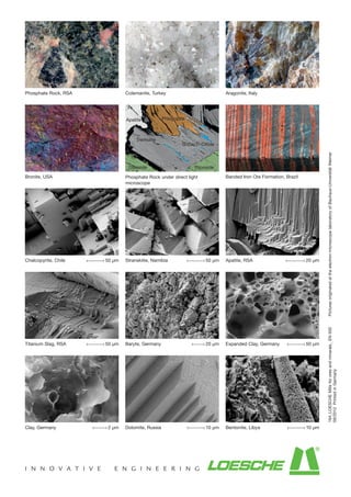
  • 1. 164_LOESCHEMillsfororesandminerals_EN500PicturesoriginatedattheelectronmicroscopelaboratoryofBauhaus-UniversitätWeimar 09/2012PrintedinGermany Phosphate Rock, RSA Colemanite, Turkey Aragonite, Italy Bronite, USA Phosphate Rock under direct light microscope Banded Iron Ore Formation, Brazil Chalcopyrite, Chile 50 µm Stranskiite, Namibia 50 µm Apatite, RSA 20 µm Titanium Slag, RSA 50 µm Baryte, Germany 20 µm Expanded Clay, Germany 50 µm Clay, Germany 2 µm Dolomite, Russia 10 µm Bentonite, Libya 10 µm Apatite Phlogopite Si-Ca-Ti-OXide Tremolite DiposideDiposide
  • 3. Loesche technology – always one step ahead 2 The company Loesche has more than 100 years of experience in the comminution of coal, cement raw material, clinker, slag and minerals. With consistently new developments, Loesche is always one step ahead. Since 1961 Loesche mills have been successfully used in the ore industry. 1961 Delivery of the first mill for phosphate rock, LM 12.20, Japan 1967 Commissioning of a Loesche mill, LM 12/850, for comminution of magnesite, Mitsuhahmi, Japan 1973 Delivery of the first Loesche mill for comminution of manganese dioxide, LM 9/760, Thessaloniki, Greece 1976 First use of a Loesche mill for comminution of baryte, LM 14/1120, Ijmuiden, Netherlands 1987 Installation of a Loesche mill for comminution of lithium feldspar, LM 13.2, Bikita, Zimbabwe 1993 Delivery of the first Loesche mill for comminution of copper matte, LM 31.2, Magna, USA 1993 Delivery of a Loesche overflow mill for titanium slag, LM 13.2, Vredenburg, RSA 1998 Installation of up to that point the largest Loesche mill for comminution of phosphate rock, LM 50.4, Phalabora, RSA 1999 Delivery of a Loesche mill for the test facility of Anglo Research for comminution of different ore types, LM 3.6, Johannesburg, RSA 2001 Delivery of a Loesche overflow mill for comminution of titanium slag, LM 13.2, Empagnini, RSA 2006 Commissioning of a Loesche mill for comminution of colemanite, LM 19. Loesche Mill Type LM 60.4, Ras al Khaima, United Arab Emirates, 2006
  • 4. 3 Loesche grinding technology is a dry milling process which offers significant advantages over conventional crushing and grinding technologies in ore beneficiation • Low specific energy consumption • Steep product particle size curve • Reduced product overgrinding • In-bed comminution • Selective comminution • Higher degree of liberation of the valuable minerals • Combining of the crushing and grinding process stages • Rapid response to changes in the feed composition • Optimisation of throughput through online monitoring • The grinding product has a positive effect on the down- stream processes • Compact design Loesche grinding technology is particularly suitable for users: • who aim to increase their recovery of respective ores and minerals by applying the Loesche grinding technology • who must reduce their operating costs • who are dependent on a limited or expensive energy supply • who operate or are planning ore processing in arid regions • who operate obsolete or inefficient grinding systems • whose processing plants no longer comply with the ecologi- cal requirements • whose space requirement for the building of complete plants or modernisation of plant parts is limited Loesche Mill Type LM 46.4, Lengerich, Germany, 2003 Loesche Mill Type LM 60.4, Ras al Khaima, United Arab Emirates, 2006
  • 5. Principle of operation 4 Loesche grinding technologies allow users to choose different comminution principles. The spectrum ranges from a combina- tion of compressive and shear stress right through to shear-free grinding, or pure compressive comminution. The grinding material is comminuted in the Loesche mill between the rotating grinding track and the stationary grinding rollers. There are two basic types of roller axis position in relation to the centre of rotation of the grinding plate. This gives rise to differ- ent comminution effects: • Compressive comminution with shear component • Pure compressive comminution. Generally speaking, Loesche mills operate with a compressive comminution system with a shear component. This effect is cre- ated by tapered rollers, whose axes are angled below 15° with respect to the horizontal grinding track. The roller axes do not intersect the centre of rotation of the grinding plate. With pure compressive comminution, the introduction of shear forces is deliberately avoided. This is achieved by tapered rollers, whose axes are angled in relation to the horizontal grinding track in such a way that the roller axis intersects exactly the centre of rotation of the grinding plate with its axis. The different comminution principles are matched to the respective ore characteristics in order to achieve optimum mineral liberation. If an ore reacts positively to shear stress, a combination of com- pressive and shear is used. The Loesche patented shear-free grinding is used where pure compressive comminution is desired. Through the use of shear- free grinding the percent-age of finest grain can be additionally reduced with regard to the already steep product particle size curve. At the same time the percentage of medium grain size fractions is increased. Further positive effects are additional energy savings and the minimisation of wear. The grinding product altered by shear-free grinding can reduce the amount of fines up to 50 % and thereby result in significant advantages for the downstream sorting processes. α´α
  • 6. 5 100 90 80 70 60 50 40 30 20 10 0 1 10 100 1000 particle size [µm] Accumulatedscreenunderflow[weight%] Compressive and shear stress Comparison of the Loesche comminution principles Shear-free grinding
  • 7. Advantages of the Loesche grinding process for ore beneficiation 6 Grinding is of central importance to the downstream sorting pro- cesses. The more complete the mineral liberation of the ground ore, the greater the chances of obtaining a good recovery. The Loesche grinding principle is based on in-bed comminution. Due to the fact that the particles have many points of contact with each other, the grinding force is directed through the grind- ing bed. This results in a better degree of liberation compared with conventional grinding technologies. Online monitoring of the operating pressure of the grinding rollers and thus of the grinding forces provides a controllable and consistent product fineness. Monitoring of the grinding forces in combination with in-bed comminution provides a selective ore comminution. Direct classifying after each grinding contact helps to avoid unwanted overgrinding and to achieve a steep product particle size curve. In addition to the energy benefits, this has above all positive effects on the downstream sorting processes. With a maximum feed grain size of 150 mm and grinding prod- ucts up to P80 of 20 µm, the Loesche mill combines the crushing and grinding process stages in a single aggregate. Accordingly, the Loesche mill can, depending on process management, substitute two to three crushing and grinding stages. As well as simplifying process management, the compact design of Loesche grinding technology reduces the “plant footprint”. In this way, the Loesche mill can be easily planned for incorpo- ration in existing plant concepts or, in the case of new planning concepts, can reduce the amount of surface area used. 100 90 80 70 60 50 40 30 20 10 0 100 1000 Particle size distribution of a Loesche Mill compared to a Ball Mill Accumulativescreenthroughput[weight%] Particle size [µm] Ball Mill Loesche Mill F F FF F
  • 8. 7 70 60 50 40 30 20 10 0 < 38 38 53 75 106 Degree of liberation Optimum flotation range Degreeofliberation[%] Particle size µm] Zn ore (as example) • SAG + Ball Mill • Loesche Mill The advantages of the Loesche grinding process over conven- tional grinding systems can be summarised as follows: • Controlled grinding; thus specific liberation of the valuable mineral • Selective comminution by means of in-bed comminution • Minimisation of product overgrinding • steeper product particle size curve – minimises the amount of finest grain – minimises the amount of coarse grain – thus improved fine-tuning of downstream sorting processes possible • Higher degree of liberation • Dry grinding product improves metering and conditioning of the following downstream process stages • Activation of particle surfaces Advantages for the downstream process The use of Loesche grinding technology delivers not only advantages in the grinding process but also in the downstream ore-sorting processes. These advantages can be put down to the grinding characteristics of the Loesche mill and thus the optimised grinding product. Flotation • Flotation kinetics is improved through the grinding products • The recovery can be increased thanks to the improved liberation of the valuable mineral • Improved grade recovery relation • The flotation times can be reduced, while recovery remains the same • Energy savings of up to 45% can be achieved compared with conventional crushing and grinding circuits • The operating costs are reduced by savings on personnel, energy and grinding auxiliaries • Reduction of specific wear • Use in arid or permafrost regions is possible • Water consumption is reduced • The Loesche grinding process is self-regulating such that the mill always runs at its optimum operating point • Improvement in the environmental balance sheet thanks to conservation of resources • Reduced consumption of flotation reagent thanks to low fines • Dry grinding product provides for precise metering and conditioning • Reduced mineral surface lining by finest grain and thus improved collector absorption
  • 9. 8 Density sorting: • Improved recovery thanks to a better degree of liberation at coarser feed size • Improved concentrate grade thanks to a reduced amount of finest particles in the feed Heap and agitator leaching: • Improved ore leaching solution contact thanks to higher liberation of valuable material and thus increased recovery • Improved leaching solution flow through the heap by reduced amount of fineness • Improved leaching kinetics Magnetic separation: • Higher recovery thanks to coarser feed size • Reduced losses of valuable mineral in the finest particle fraction Water management • Reduced water consumption • Reduced problem of slimes during filtration • Improved recovery of process water thanks to reduced water absorption at the slimes and faster sedimentation of the tailings Grade recovery curve Concentrate grade [g/t] Recovery [%] Loesche Mill Ball Mill 10 20[min 30t1 t2 t´1 t´2 Flotation kineticsRecovery [%] Retention time [min]; t Ball Mill Loesche Mill
  • 10. 9 Loesche Overflow Mill Type LM 13.2 SP, Namakwa Sands, South Africa, 1993
  • 11. Customer benefit and customer satisfaction 10 Quality and reliability from the outset are the internationally recognised advantages of Loesche grinding plants. Ever since 1928, when the Loesche mill was first introduced to the market, the principle of the vertical roller mill with rotating grinding track and individually guided rollers has proven to be particularly energy- and resource-conserving. These advantages of the Loesche mill are becoming increas- ingly more important in the face of increasing plant sizes and commitment to more economical use of resources, such as energy, water, etc. Furthermore, because of the high product rates for Loesche mills the investment costs are significantly lower compared to smaller grinding plants. From sales through to aftersales service, from project planning on schedule through to the handover of plants, Loesche is a competent partner to its customers. Our maxim is: “Every Loesche grinding plant is a reference plant!” The cornerstones of our competence include: • Customised plant concepts from planning through to com- missioning, based on our own knowledge and experience, paired with customer requirements • Individual problem solutions with optimised process technology • Close cooperation with suppliers of further processing equipment according to customer requirements • Customer service: plant optimisations and advice on new technical developments • Long-term commitment to deliver spare parts • Certification to EN ISO 9001: 2008. Central grinding plant for granulated blast furnance slag, Loesche Mill Type LM 35 2+2, Rouen, France, 2003
  • 12. 11 Loesche Mill Type LM 69.6 under construction, Idhan, UAE, 2009
  • 13. Layout and function of the Loesche mill 12 Layout The established basic principle of the modular system patented in 1970 is used for Loesche mills with two, three, four and six roller modules. Each roller module consists of the grinding roller, a rocker arm that transmits force to the roller by hydraulic spring loading, and the upper end of which the rocker arm is supported so that it can pivot. Large or small modules can be used in dif- ferent numbers (two, three, four and six) in identical mill sizes (grinding table diameter). In this way, customer-specific require- ments can be satisfied on a customised basis. Loesche technology is characterised by the following features: • Each roller is held by a locally secured rocker arm. • The roller-bearing-mounted rocker arm roller system is sup- ported and guided precisely in a pedestal with integrated spring assembly. • The facility to raise the rollers serves as a starting aid for the mill during startup with the grinding track filled. It is an integral part of the hydropneumatic spring assembly. • In each case two opposing rollers are connected to a com- mon hydraulic unit (except on 3-roller mills). • A virtually parallel grinding gap is maintained for the entire service life of the grinding parts between the grinding rollers and the grinding plates of the grinding table. • Via the hydraulic system the grinding force can be optimised in correspondence with the characteristics of the comminut- ing ores. Mill function, airflow mode The ore raw material is fed via an air lock 1 1110 2 12 3 13 4 14 5 15 6 16 7 17 8 18 9 19 20 21 22 23 24 25 26 27 28 and falls via the chute1 1110 2 12 3 13 4 14 5 15 6 16 7 17 8 18 9 19 20 21 22 23 24 25 26 27 28 onto the centre of the grinding tabel1 1110 2 12 3 13 4 14 5 15 6 16 7 17 8 18 9 19 20 21 22 23 24 25 26 27 28 . Free ferrous foreign objects are separated out from the feed material mag- netically before reaching the air lock 1 1110 2 12 3 13 4 14 5 15 6 16 7 17 8 18 9 19 20 21 22 23 24 25 26 27 28 and removed via a diverter gate. A metal detector operates in a similar way and ensures the separation of non-magnetic metal parts. The mate- rial to be ground moves on the grinding track towards the edge of the grinding table under the effect of centrifugal force and in this way passes under the hydropneumatically spring-loaded grinding rollers1 1110 2 12 3 13 4 14 5 15 6 16 7 17 8 18 9 19 20 21 22 23 24 25 26 27 28 . The material that has been drawn in is ground in the material bed in the gap between the rollers and grinding track. The rollers1 1110 2 12 3 13 4 14 5 15 6 16 7 17 8 18 9 19 20 21 22 23 24 25 26 27 28 are displaced upwards as they roll over the material bed1 1110 2 12 3 13 4 14 5 15 6 16 7 17 8 18 9 19 20 21 22 23 24 25 26 27 28 . As a result the functional unit consist- ing of rocker arm1 1110 2 12 3 13 4 14 5 15 6 16 7 17 8 18 9 19 20 21 22 23 24 25 26 27 28 , spring rod and pistons from the hydraulic cylinder1 1110 2 12 3 13 4 14 5 15 6 16 7 17 8 18 9 19 20 21 22 23 24 25 26 27 28 are moved. The piston displaces the hydraulic oil from the cylinder into the gas-filled bladder accumulator unit. Nitrogen-filled rubber bladders in the accumulator units are compressed and act as gas springs. The gas springs can be set to be harder or softer by selecting the gas pressure in relation to the hydraulic operating pressure, depending on the fracture behaviour of the material to be ground. The ground material is subjected to centrifugal force and rotates outwards and over the edge of the grinding table. In the area of the louvre ring1 1110 2 12 3 13 4 14 5 15 6 16 7 17 8 18 9 19 20 21 22 23 24 25 26 27 28 which surrounds the grinding table1 1110 2 12 3 13 4 14 5 15 6 16 7 17 8 20 21 22 23 24 25 26 27 the stream of hot gas1 1110 2 12 3 13 4 14 5 15 6 16 7 17 8 18 9 19 20 21 22 23 24 25 26 27 28 directed upwards captures the mixture of ground material and material as yet not completely ground and conveys this to the classifier 1 1110 2 12 3 13 4 14 5 15 6 16 7 17 8 18 9 19 20 21 22 23 24 25 26 27 28 . Depending on settings of the classifier 1 1110 2 12 3 13 4 14 5 15 6 16 7 17 8 18 9 19 20 21 22 23 24 25 26 27 28 it rejects coarse materials. This falls into the internal grit return cone 1 1110 2 12 3 13 4 14 5 15 6 16 7 17 8 20 21 22 23 24 25 26 27 and then onto the grinding table1 1110 2 12 3 13 4 14 5 15 6 16 7 17 8 18 9 19 20 21 22 23 24 25 26 27 28 for regrinding. The ground material passes from the classifier and is conveyed from the Loesche mill with the gas stream 1 1110 2 12 3 13 4 14 5 15 6 16 7 17 8 18 9 19 20 21 22 23 24 25 26 27 28 . Foreign matter and small amounts of coarse material fall through the louvre ring1 1110 2 12 3 13 4 14 5 15 6 16 7 17 8 18 9 19 20 21 22 23 24 25 26 27 28 into the ring channel 1 1110 2 12 3 13 4 14 5 15 6 16 7 17 8 18 9 19 20 21 22 23 24 25 26 27 28 as reject material. Scrapers 1 1110 2 12 3 13 4 14 5 15 6 16 7 17 8 18 9 19 20 21 22 23 24 25 26 27 28 connected to the grinding table transport foreign matter into the reject chute 1 1110 2 12 3 13 4 14 5 15 6 16 7 17 8 18 9 19 20 21 22 23 24 25 26 27 28 .
  • 14. 1 1110 2 12 3 13 4 14 5 15 6 16 7 17 8 18 9 19 20 21 22 23 24 25 26 27 28 1 1110 2 12 3 13 4 14 5 15 6 16 7 17 8 18 9 19 20 21 22 23 24 25 26 27 28 1 1110 2 12 3 13 4 14 5 15 6 16 7 17 8 18 9 19 20 21 22 23 24 25 26 27 28 1 1110 2 12 3 13 4 14 5 15 6 16 7 17 8 18 9 19 20 21 22 23 24 25 26 27 28 1 1110 2 12 3 13 4 14 5 15 6 16 7 17 8 18 9 19 20 21 22 23 24 25 26 27 28 1 1110 2 12 3 13 4 14 5 15 6 16 7 17 8 18 9 19 20 21 22 23 24 25 26 27 28 1 1110 2 12 3 13 4 14 5 15 6 16 7 17 8 18 9 19 20 21 22 23 24 25 26 27 28 1 1110 2 12 3 13 4 14 5 15 6 16 7 17 8 18 9 19 20 21 22 23 24 25 26 27 28 1 1110 2 12 3 13 4 14 5 15 6 16 7 17 8 18 9 19 20 21 22 23 24 25 26 27 28 1 1110 2 12 3 13 4 14 5 15 6 16 7 17 8 18 9 19 20 21 22 23 24 25 26 27 28 1 1110 2 12 3 13 4 14 5 15 6 16 7 17 8 18 9 19 20 21 22 23 24 25 26 27 28 1 1110 2 12 3 13 4 14 5 15 6 16 7 17 8 18 9 19 20 21 22 23 24 25 26 27 28 1 1110 2 12 3 13 4 14 5 15 6 16 7 17 8 18 9 19 20 21 22 23 24 25 26 27 28 1 1110 2 12 3 13 4 14 5 15 6 16 7 17 8 18 9 19 20 21 22 23 24 25 26 27 28 1 1110 2 12 3 13 4 14 5 15 6 16 7 17 8 18 9 19 20 21 22 23 24 25 26 27 28 1 1110 2 12 3 13 4 14 5 15 6 16 7 17 8 18 9 19 20 21 22 23 24 25 26 27 28 1 1110 2 12 3 13 4 14 5 15 6 16 7 17 8 18 9 19 20 21 22 23 24 25 26 27 28 1 1110 2 12 3 13 4 14 5 15 6 16 7 17 8 18 9 19 20 21 22 23 24 25 26 27 28
  • 15. 14 The grinding table is driven by an electric motor 1 1110 2 12 3 13 4 14 5 15 6 16 7 17 8 18 9 19 20 21 22 23 24 25 26 27 28 via an elas- tic coupling 1 1110 2 12 3 13 4 14 5 15 6 16 7 17 8 18 9 19 20 21 22 23 24 25 26 27 28 and the mill gearbox with vertical output 1 1110 2 12 3 13 4 14 5 15 6 16 7 17 8 18 9 19 20 21 22 23 24 25 26 27 28 . A segmental thrust bearing at the top of the gearbox absorbs the grinding forces. Before the mill motor is started, the grinding rollers1 1110 2 12 3 13 4 14 5 15 6 16 7 17 8 18 9 19 20 21 22 23 24 25 26 27 28 are lifted hydraulically from the grinding track. The mill can then be started at low starting torque not only empty, but also partially filled. The grinding parts are prevented from coming into metal- lic contact when the mill is empty or loaded by automatic lifting of the rollers via a level control. A so-called “auxiliary drive” for starting up a filled mill at low revolutions is not necessary! Mill function, overflow mode In the case of ores with specific grinding characteristics or coarse comminution, it might be beneficial to separate the grinding and classifying processes. Overflow mode is selected for such materials. In contrast to airflow mode, classifying in overflow mode takes place not in the classifier directly above the grinding chamber, but in an external classifier. The material is transported via corresponding conveying routes from the mill to the external classifier. The material ground by the grinding rollers is conveyed by the centrifugal forces of the rotating grinding table over the dam ring into the ring duct. As a result of the high circulation of material it is discharged from the ring duct not by means of a scraper, but instead in a free material flow via sloping chutes. Maintenance Worn grinding parts, tires and grinding track segments can be easily and quickly changed. The rollers are retracted out of the grinding chamber into a vertical position with a swinging-out cylinder. Complete rollers, tires and grinding plates are thus made accessible for lifting gear. During grinding the grinding parts wear out for the most part over the entire service life to such a uniform extent that mill throughput decreases only when the grinding parts are com- pletely worn. Partial wear can be compensated for by specific lining in the mill. This can be realised by removal of the grinding parts or insitu by means of a special welding unit. Loesche has the necessary expertise for welding insitu with appropriate welding apparatus. Hardfacing the grinding tire inside the mill Service drive
  • 16. Combined drying and grinding and classifying 15 Combined drying and grinding Ore raw material may be obtained with different moisture contents as a result of the upstream separation processes. However, when compared with a moist product, a dry grinding product allows for more exact metering and conditioning to the downstream sorting process. Hot gases are supplied to the combined drying and grinding process to evaporate the material moisture. Hot gases can either be used from on site sources or by using the Loesche hot gas generator. As soon as the ground material leaves the table for the area above the louvre ring, the water contained in the feed material evaporates spontaneously on contact with the hot-gas flow. Classifying Depending on the application, Loesche vertical roller grinding mills can be operated in so-called airflow or overflow mode. In both modes direct classifying after the grinding process elimi- nates the risk of product overgrinding. Airflow mode combines the functions of grinding and classify- ing in one aggregate. The air flow uplifts the material from the grinding chamber to the classifier. In the classifier above the grinding chamber the material ground to spec is separated from the coarse particles (grit), which can drop back onto the grinding table to be comminuted again or can be removed for further treatment. In overflow mode the ground material is discharged over the edge of the grinding table and classified in an external process. The grit is fed back into the grinding chamber. By isolating the classifying process from the grinding process, it is possible to provide for several classifying or sorting stages in order to recover intermediate products. Dynamic Loesche classifier (LSKS) The Loesche LSKS-type caged-rotor classifier operates with highly selective separation. It produces grain distributions of both narrow and wide bandwidths. By varying the process- technology setting parameters and thanks to appropriate built- in classifier components, it is possible to satisfy these differing demands made of the grain structure. The gas/particle flow rising from the mills is directed via a static guide vane assembly1 1110 2 12 3 13 4 14 5 15 6 16 7 17 8 18 9 19 20 21 22 23 24 25 26 27 28 to the classifying chamber. The gas/ solid-matter mixture flows, depending on the flap position, spe- cifically into the space between the guide vane assembly1 1110 2 12 3 13 4 14 5 15 6 16 7 17 8 18 9 19 20 21 22 23 24 25 26 27 28 and the concentric-running rotor with blades1 1110 2 12 3 13 4 14 5 15 6 16 7 17 8 18 9 19 20 21 22 23 24 25 26 27 28 . As it rotates, the rotor accelerates the supplied gas/solid-matter mixture tangentially. The centrifugal force generated in the pro- cess rejects oversized grain. The rotor speed and the gas flow with its flow direction deter- mine the desired separation diameter. This can be adjusted within wide limits. A unique feature of this classifier type is the continuous reclas- sifying of the particle flows rejected by the rotor. When they fly outwards under centrifugal force in the annular gap, they are blasted again by the gas flow directed upwards/inwards. Here agglomerated particles dissolve in such a way that they follow the product flow as individual grains and do not drop as appa- rent oversized grains with the grit back onto the grinding table. Layout: 1 1110 2 12 3 13 4 14 5 15 6 16 7 17 8 18 9 19 20 21 22 23 24 25 26 27 28 Grit cone 1 1110 2 12 3 13 4 14 5 15 6 16 7 17 8 18 9 19 20 21 22 23 24 25 26 27 28 Guide vane assembly 1 1110 2 12 3 13 4 14 5 15 6 16 7 17 8 18 9 19 20 21 22 23 24 25 26 27 28 Rotor with blades 1 1110 2 12 3 13 4 14 5 15 6 16 7 17 8 18 9 19 20 21 22 23 24 25 26 27 28 Rotor shaft 1 1110 2 12 3 13 4 14 5 15 6 16 7 17 8 18 9 19 20 21 22 23 24 25 26 27 28 Housing 1 1110 2 12 3 13 4 14 5 15 6 16 7 17 8 18 9 19 20 21 22 23 24 25 26 27 28 Material feed chute 1 1110 2 12 3 13 4 14 5 15 6 16 7 17 8 18 9 19 20 21 22 23 24 25 26 27 28 Product discharge 1 1110 2 12 3 13 4 14 5 15 6 16 7 17 8 18 9 1 20 21 22 23 24 25 26 27 28 1 1110 2 12 3 13 4 14 5 15 6 16 7 17 8 18 9 19 20 21 22 23 24 25 26 27 281 1110 2 12 3 13 4 14 5 15 6 16 7 17 8 18 9 19 20 21 22 23 24 25 26 27 28 1 1110 2 12 3 13 4 14 5 15 6 16 7 17 8 1 20 21 22 23 24 25 26 27 21 1110 2 12 3 13 4 14 5 15 6 16 7 17 8 18 9 19 20 21 22 23 24 25 26 27 28 1 1110 2 12 3 13 4 14 5 15 6 16 7 17 8 18 9 20 21 22 23 24 25 26 27 28 1 1110 2 12 3 13 4 14 5 15 6 16 7 17 8 18 9 19 20 21 22 23 24 25 26 27 28
  • 17. Sizing – model series – drives 16 Dimensioning parameters The following standard parameters are decisive in the sizing of Loesche mills: • GRINDING PRESSURE This lies between the minimum value for solid fuels and the maximum value for ores. • MATERIAL MOISTURE The Loesche mill can process material with moisture of up to 25%. • PRODUCT FINENESS In the case of air-classifying it is possible, depending on the customer requirement, to create product fineness figures of P80 of 500 μm to P80 of 20 μm. • DRIVE POWER The specific energy consumption during the grinding test is decisive for gearbox and motor power. In the development history of Loesche mills the sizes have been adapted to the constant demand for higher capacity and throughput figures. The modular construction of the mills also enables customer-specific solutions to be realised by combin- ing standard components. Model series • The mill sizes are identified according to the outer effective diameter of the grinding track in decimetres [dm]. • The identification is – separated by a point – followed by a digit. This digit indicates the number of rollers operating in the mill. • Loesche mills are modular in design. The units of rollers, rocker arms and rocker-related spring assembly compo- nents with their pedestal are the modules. They are arranged as required 2, 3, 4 and 6 times around a grinding table. • The number and size of the rollers is dependent on the required product rate in conjunction with the “Loesche load factor”, the product of the grindability, moisture and fine- ness factors. The required gas flow is decisive for sizing the housings of the mill and the classifier.
  • 18. 17 Drives An electric motor is used as the drive. It drives a planetary gear- box with bevel gears. The input shaft is horizontal, the output shaft operates vertically upwards. The drive is enclosed at the top by a horizontal output flange. The gearbox contains a seg- mental thrust bearing which absorbs the grinding forces in the housing at the top. Loesche mill gearboxes are developed in cooperation between Loesche GmbH and well-known gearbox manufacturers. The field service conditions under which the gearboxes must operate are matched to each other. Decades of field experience with Loesche mills determine the design of the (mill) gearboxes and their peripherals under all climatic condi- tions. Today’s modern gearboxes are, like Loesche mills, modular in design. Torque split provides for a reduction of rotating masses with simultaneous multiple use of engineering elements in gear- boxes of different sizes and power outputs. A lubrication unit ensures that the gear teeth, the shaft bearings and the segmental thrust bearing are supplied with sufficient oil. Filters and cooling systems condition the oil. Electrical and hydraulic monitoring instruments incorporated in the PLC ensu- re safe operation. In accordance with today’s state-of-the technology the modular construction principle of gearboxes allows further power incre- ases without the need to develop a new construction concept. The Loesche mill does not require a motor with increased star- ting torque. Because the rollers are hydraulically raised, the breakaway torque of the filled mill amounts to only 40% of the full-load torque. A “standard motor” can easily deliver this star- ting torque. The installed motor power is geared towards the mill’s energy demand and is determined in the Loesche technical centre duri- ng the grinding test. The closest matching commercially availa- ble motor is selected and recommended to the customer. Loesche mill gearbox
  • 19. Complete grinding plants 18 Complete grinding plants An ore grinding plant is featured on the following page. Grinding plants that use Loesche mills are characterised primarily by their simple design and layout. A grinding plant consists of the following process stages and components: • Material feeding • Grinding and classifying • Reject/circulation handling • Product separation • Mill fan • Hot gas generator (optional) • Process/measuring and control technology Complete grinding plants incorporate material storage hoppers and conveyor systems suitable for the ore industry as well as metering elements to the Loesche mill. Included downstream of the classifying processes is a filter system, which features, as well as the actual filter and the piping system, the product dischargea and process-air circuit assemblies. The Loesche grinding plant also features components for metal separation and Loesche’s own hot gas generators for drying purposes, if these are required for the process. Material which has not yet attained the desired product particle size is returned to the grinding process. Final product is intermediately stored in the hopper and is for- warded from there to the downstream processes. Complete Loesche grinding plant with mill and filter
  • 20. 19 Overflow and airflow modes The Loesche grinding plant is incorporated between the primary crusher and the downstream process in an ore beneficiation plant. There are essentially two different processes for commi- nuting ores with the Loesche mill. The difference being whether the recirculating load is conveyed in an internal or external circuit. When the ground ore leaves the grinding chamber after the grinding process under its own gravitational force, this is known as overflow mode. When the material is discharged by means of an air flow via a classifier, this is known as airflow mode. The choice of mode is determined by the properties of the material and the objective of the grinding process. Overflow mode In the overflow mode the classification and grinding processes are separate. The material is transported from the mill to the classifier via appropriate conveying systems. Prior to feeding the mill, the ore is classified in the pre- classifying stage. Ore already according to spec is separated in the pre-classifier and guided to the final classifying stage the dynamic classifier. Thereby overgrinding and unnecessary energy consumption are prevented. The coarse fractions of the pre-classifier and the dynamic classifier are fed to the mill. After the material has been ground it is discharged through the ring duct and re-fed to the pre-classifier, thereby the grinding classifying circuit is closed. The final product of the dynamic classifier is separated in the filter. Airflow mode In airflow mode grinding and classifying are combined in a single machine (Loesche mill with classifier). Within the mill and to the classifier the material is transported via airflow. The feed material from the primary crushing stage is directed after upstream metal separation into the grinding chamber of the Loesche mill. The ground material is directed with the upris- ing gas flow into the classifier. The grit drops back onto the grinding table and is comminuted again. Product of sufficient fineness passes the classifier and is separated in the filter. In both processes the finished grinding product is finally removed from the filters and fed to the downstream process via a product buffer. Both overflow and airflow modes are closed grinding/classify- ing circuits. By constant separation of the final product from the grinding process an overgrinding of the material can be avoided. Loesche overflow mill
  • 21.
  • 22.
  • 24. 23 Loesche overflow mill 1 Feed, crushing plant 2 Conveyor belt, mill feed 3 Overbelt magnet 4 Metal detector 5 2-way chute 6 Defective material collector 7 Conveyor belt, classifier charge 8 Static classifier 9 Dynamic classifier 10 Conveyor belt 11 Loesche mill 12 Discharge system 13 Conveyor belt circulation 14 Filter system 15 Filter fan 16 Stack 17 Product discharge 18 Recirculation gas line with dumper (optional) 19 Hot gas generator (optional) 20 Product storage Loesche airflow mill 1 Feed, crushing plant 2 Conveyor belt, mill feed 3 Overbelt magnet 4 Metal detector 5 2-way chute 6 Defective material collector 7 Gate 8 Loesche mill 9 Reject system 10 Conveyor belt, reject system 11 Filter system 12 Filter fan 13 Stack 14 Product discharge 15 Recirculation gas line with dumper (optional) 16 Hot gas generator (optional) 17 Product storage Downstream processes Downstream processes
  • 25. 1 1110 2 12 3 13 4 14 5 15 6 16 7 17 8 18 9 19 20 21 22 23 24 25 26 27 28 1 1110 2 12 3 13 4 14 5 15 6 16 7 17 8 18 9 19 20 21 22 23 24 25 26 27 28 1 1110 2 12 3 13 4 14 5 15 6 16 7 17 8 18 9 19 20 21 22 23 24 25 26 27 28 13 4 14 5 15 6 16 7 17 8 18 9 19 23 24 25 26 27 28 12 3 13 4 14 5 15 6 16 7 17 8 18 9 19 22 23 24 25 26 27 28 1 1110 2 12 3 13 4 14 5 15 6 16 7 17 8 18 9 19 20 21 22 23 24 25 26 27 28 1 1110 2 12 3 13 4 14 5 15 6 16 7 17 8 18 9 19 20 21 22 23 24 25 26 27 28 1 1110 2 12 3 13 4 14 5 15 6 16 7 17 8 18 9 19 20 21 22 23 24 25 26 27 28 1 1110 2 12 3 13 4 14 5 15 6 16 7 17 8 18 9 19 20 21 22 23 24 25 26 27 28 1 1110 2 12 3 13 4 14 5 15 6 16 7 17 8 18 9 19 20 21 22 23 24 25 26 27 28 Construction 1 1110 2 12 3 13 4 14 5 15 6 16 7 17 8 18 9 19 20 21 22 23 24 25 26 27 28 Burner 1 1110 2 12 3 13 4 14 5 15 6 16 7 17 8 18 9 19 20 21 22 23 24 25 26 27 28 Fuel 1 1110 2 12 3 13 4 14 5 15 6 16 7 17 8 18 9 19 20 21 22 23 24 25 26 27 28 Combustion air 1 1110 2 12 3 13 4 14 5 15 6 16 7 17 8 18 9 19 20 21 22 23 24 25 26 27 28 Burner muffle 1 1110 2 12 3 13 4 14 5 15 6 16 7 17 8 18 9 19 20 21 22 23 24 25 26 27 28 Spiral housing 1 1110 2 12 3 13 4 14 5 15 6 16 7 17 8 18 9 19 20 21 22 23 24 25 26 27 28 Perforated jacket 1 1110 2 12 3 13 4 14 5 15 6 16 7 17 8 18 9 19 20 21 22 23 24 25 26 27 28 Annular gap 1 1110 2 12 3 13 4 14 5 15 6 16 7 17 8 18 9 19 20 21 22 23 24 25 26 27 28 Protective casing 1 1110 2 12 3 13 4 14 5 15 6 16 7 17 8 18 9 19 20 21 22 23 24 25 26 27 28 Temperature control1 1110 2 12 3 13 4 14 5 15 6 16 7 17 8 18 9 19 20 21 22 23 24 25 26 27 28 Hot gas outlet Loesche hot gas generator 24 The perforated jacket combustion system developed by Loesche in the mid 1960’s consists of a combustion chamber of heat resistant steel with burner muffle, and is well known in the market under the name LOMA Hot Gas Generator. The LOMA Hot Gas Generator has been used worldwide for decades in many different types of thermal processes for optimization. Design and operation: • The combustion chamber consists of heat resistant steels – no refractory brickwork is necessary • When starting up the hot gas generator heat losses are minimised since it is not necessary to heat up refractory brickwork. A start at full load is therefore possible. • Very good thermal shock resistance and rapid load changes with only a short delay • High cooling rate of the combustion chamber prevents ther- mal overloading of following units.An EMERGENCY chimney stack is not necessary in EMERGENCY-OFF SITUATIONS and when starting and stopping. • Accessible within a short time for inspection • Low wear • Short installation times, low weight, small space require- ment. Can be installed in existing plants. Complete preas- sembly is carried out – also for larger LOMA combustion units. Loesche hot gas generators are used where hot gases are required for direct drying, e.g. in the cement, steel, industrial minerals, ore, wood, cattle food, agri-food and chemical indu- stries. Mode of operation The process gas stream which enters the spiral housing1 1110 2 12 3 13 4 14 5 15 6 16 7 17 8 18 9 19 20 21 22 23 24 25 26 27 28 cools both the protective jacket housing1 1110 2 12 3 13 4 14 5 15 6 16 7 17 8 18 9 19 20 21 22 23 24 25 26 27 28 and the perforated jacket 1 1110 2 12 3 13 4 14 5 15 6 16 7 17 8 18 9 19 20 21 22 23 24 25 26 27 28 . as a result of the flow pattern. The process gas enters the interior of the combustion chamber through the annular gap1 1110 2 12 3 13 4 14 5 15 6 16 7 17 8 18 9 19 20 21 22 23 24 25 26 27 28 and holes in the perforated jacket, and mixes there with the hot flue gases from combustion. At the same time the flame and hot flue gases are kept away from the perforated jacket. Heating media • Natural gas, bio gas, coke gas, blast furnace gas and other low calorific value gases • Light and heavy oils, wood and lignite dust LOMA Hot Gas Generator units are constantly being developed and conform to current technical standards. More than 600 hot gas generators (of this type) have been commissioned for a heat flow of between 100 kW and 64,000 kW. LOMA combustion unit type LF 25 with a natural gas burner, 2005
  • 26. Loesche rotary vane feeder 25 Feeding of Loesche CS mills is carried out via a rotary vane feeder in order to prevent false air ingress into the mill interior. Material is fed continuously from above via the inlet hopper into every vane pocket of the slowly rotating vane feeder. In order to reduce wear from the abrasive feed stock the peripheral speed is low and the filling level limited to 40%. Adjustable sealing strips on the rotor prevent any large gaps between the wearing plate of the housing and the rotor. The material is discharged downwards into the feed chute of the mill. Hot gas can be passed through the inside of the rotary feeder to prevent material caking. It is easy to dismantle for maintenance purposes.
  • 27. The Loesche test facility for raw materials testing, Research and Development Calibrated standard grinding tests for mill sizing Loesche has many years of experience in designing grinding mills. The most important prerequisite for correctly designed grinding mills is an exact knowledge of the physical properties of the materials to be ground. The most important characteristic values of a material to be ground are the Loesche grindability factor and the specific power demand in relation to a defined fineness. Depending on the geological formation of the material to be ground, materials with highly different properties are found in nature, even with materials which appear visually to be similar. Three well equipped laboratory LM 3.6 grinding mills are avai- lable in the Loesche test plant for performing standard grinding tests. Technological development through practical laboratory grinding tests One of the first steps in introducing new technologies is the practical laboratory test. Within the framework of our research and development projects the following actions are carried out: • New materials for grinding of future market requirements are examined • Optimised mill settings for special products are determined • Plant components and process configurations are opti- mised • New wear materials and concepts are tested Our test plant is constructed in such a way that various modes of operation and plant process configurations can be simulated in the tests. Fully-automatic operation with PLC LM 3.6 laboratory mill Analysis possibilities • Pure density determination with gas pycnometer • Determination of mass-related surface according to Blaine • Grain size analysis with Cilas laser granulometer • Sieve analyses with Alpine air-jet screening method • Sieve analyses with Retsch vibrating sieves • Grindability according to Hardgrove • Grindability according to Zeisel • Microscopy with Zeiss Stemi SV11 • Drying ovens for moisture determination • Coal testing (Cfix, volatile matter, ash content) 26
  • 28. Loesche – worldwide presence Loesche is an export-oriented company run by the owner, which was established in 1906 in Berlin. Today the company is internationally active with subsidiaries, representatives and agencies world- wide. Our engineers are constantly developing new ideas and individual concepts for grinding technologies and preparation processes for the benefit of our customers. Their competence is mainly due to our worldwide information management. This ensures that current knowledge and developments can also be used immediately for our own projects. The services of our subsidiaries and agencies are of key importance for analysis, processing and solving specific project problems for our customers. Please visit our homepage at www.loesche.com for up-to-date information on our overseas companies.