SlideShare a Scribd company logo
1 of 3
OE-254 Cut Sheet
NOTES:
*Make sure the area you choose is clear with a visible line ofsight.
*Before raising the antenna,inspect all piecesof equipmentinthe antenna kit.
1. Remove all components fromOE-254 bag.
(DIAGRAMBELOW SHOWSALL THE COMPONENTSTO A COMPLETE OE-254)
2. Place base plate,grovesfacingupwardsona leveledsurface.
3. Drive the stake of the mast and base assemblythroughthe centerhole of the baseplate withthe hammer.
4. Drive the two pin stakes through opposite corner holes of the baseplate.
5. Locate the position of the four guy stake assemblies at a maximum radius of 25 feet from the center of the baseplate and a 90 degree
angle between stakes.
6. Drive the four stakes at a 60-degree angle into the ground surface facing away from the mast.
(FIGURE 2 SHOWS AN AREIAL IMAGE OF YOUR STAKE
POSITIONING)
7. Assemble five lower mast sections by inserting the male ends into the
female ends.
8. Place the bottomsection of the assembly over the movable portion of the
mast and base assembly.
9. Slide a guy plate, color coded blue, onto the male end of the lower adapter
assembly.
10. Assemble the lower adapter assembly to the five lower mast sections.
11. Assemble five upper mast sections and join them with the six already
assembled.
12. Slide a guy plate, color coded red, onto the male end of the upper adapter
assembly.
13. Assemble the upperadapter assembly to the mast.
14. Turn each guy plate so that one hole is uppermost.
15. Attach the guy hooks,color coded blue, of the four lower guy ropes to the holes of the lower guy plate.
(FIGURE 3 IS A GRAPHIC DIAGRAM ON WHERE YOU SHOULD BE IN THE
PROCESS)
16. Extend the guy ropes to the anchorassemblies
17. Attach the free guy loop of the guy snubberto the anchor hooks.
* When attached this way, each guy rope can be pulled as taut as desired by
lengthening the guy loop.
18. Attach the upperfour guys,color coded red, to the red guy plate and anchor
assemblies in a similar manner.
19. Pull the four side guy ropes, two upper and two lower, make sure the cables are
tight then secure them.
* MAKE SURE THERE IS NO SLACK IN YOUR CABLE TO INCREASE SUPPORT AND STABILITY.
20. Acquire your feedcone assembly
21. Screw the insulating extension into the feedcone structure and assemble to the mast.
(FIGURE 4 BELOW IS THE STEP YOUR
CURRENTLY ON)
22. Assemble the, antenna elements by screwing Mast Sections AB-
24, MS-117A, and MS-116A.
*ONLY 1 OF EACH ANTENNA ELEMENT SHOULD BE USED FOR 1
COMPLETE ANTENNA.
23. Attach the antenna elements to the feed cone assembly by screwing the
male ends on MS-116A into the female sockets located on feed cone
assembly.
24. Install antenna tips on each of the antenna elements and secure by wrapping with electrical tape if available.
25. Locate the point on the upper pulling guy rope where it meets the guy stake.
* The lower pulling guy should be approximately one foot shorter than the upper pulling guy.
26. Tie a slip knot with the upperand lower pulling guys at that point and return to the base with the knot in hand.
27. Grasp the slip knot firmly in both hands pull the mast off the ground.
* If available, raise the mast head off the ground up to four feet by using some kind of support box, or concrete block.
28. Walk backwards to the rear guy stake until the mast is fully erect.
* Do not pull the lower pulling guy because it will automatically tighten during the lift up.
*NOW IT’S TIME TO SET UP YOUR RADIO
29. If your MT-6352 VRC (your mounting base)is
mounted inside of a vehicle your power cable should
already be hooked up to yourJ1 power in connector.
30. Grab your radio mount bracket and slide it into the base
plate. Make sure that all the connectors in the back of the
mount are aligned, and secure the mount with the safety
lock handle located at the mount of the mount.
31. Then depending on how may radios you are using,slide
each 1523-E/F radio into its designated slot. *Only if using
one radio slide it into the bottomsection of the mount know
as alpha slot due to its long range capabilities.
32. Take the antenna cable from OE-254 and connect it to
the J1 port on the AN-7238 (AMP)
33. Then connect yourW2 cable to your J2 port and turn the power on.
YOU HAVE NOW COMPLETED THE RADIO CONNECTION PART. NOW IT’S TIME TO START THE RETRANS PORTION.
BEFORE YOU START THIS PROCESS WHAT YOU NEED TO FIND OUT IS IF YOUR RETRANSMISSION IS
TRADITIONAL OR SAME NET. THE DIFFERENCE BETWEEN BOTH IS TRADITION RETANSMISSION CONSIST OF 2
DIFFERENT SINGLE CHANNEL (SC) FREQUENCIES OR FREQUENCY HOPPING (FH) NET IDS COMMUNICATING WITH
EACH OTHER. WHILE SAME NET RETRANSMISSION STATION CONSISTS OF ONE FREQUENCY HOPPING (FH) NET
ID BEING RELAYED THROUGH THE SYSTEM
TRADITIONAL RETRANSMISSION SETUP SAME NET RETRANSMISSION SETUP
- PROGRAM THE RT-1523’S ACCORDING TO YOUR
FREQUENCY PLAN
- ESTABLISH COMMUNICATIONS WITH BOTH
ENDS BEFORE INITIATING RETRANS MODE.
- CONNECT THE RT-1523’S AT THE AUD/DATA
PORT (RXMT) USING THE CX-13298 RXMT
CABLE AND ROTATE THE RT-1523 FUNCTION
KNOB TO RXMT.
- LOAD THE RT-1523’S WITH COMSEC, INPUT THE
NET ID, JULIANDATE, AND TIME.
- ESTABLISH COMMUNICATIONS WITH BOTH
ENDS BEFORE INITIATING RETRANS
- CONNECT THE RT-1523’S AT THE AUD/DATA
PORT (RXMT) USING THE CX-13298 RXMT
CABLE AND ROTATE THE RT-1523 FUNCTION
KNOB TO RXMT.
- PRESS THE DATA (NUMBER 4 ON THE NUMBER
PAD) BUTTON AND THEN THE CHANGE (CHG)
BUTTON (NUMBER 7 ON THE NUMBER PAD)
UNTIL ESIP RXMT PX OR TX IS DISPLAYED IN
THE SCREEN OF THE RECEIVING RT-1523
- ONE RADIO WILL BE SET TO ESIP RXMT PX
ANDTHE OTHER RADIOWILL BE SET TO ESIP
RXMT TX
*ONCE ALL OF THIS IS COMPLETED CHECK AND VERIFY THAT ALL CABLES ARE SECURE AND TIGHTENED.
**YOU ARE NOW FULLY MISSION CAPABLE!

More Related Content

What's hot

Basics Of Minilink Microwave Networks
Basics Of Minilink Microwave NetworksBasics Of Minilink Microwave Networks
Basics Of Minilink Microwave NetworksAtif Mahmood
 
Os rtos.ppt
Os rtos.pptOs rtos.ppt
Os rtos.pptrahul km
 
config_mini link
config_mini linkconfig_mini link
config_mini linkAmir Moradi
 
Routing over ericsson mini link
Routing over ericsson mini linkRouting over ericsson mini link
Routing over ericsson mini linkAhmed Nabeeh
 
Tele rf basic of drive test
Tele rf basic of drive test Tele rf basic of drive test
Tele rf basic of drive test MohaSyed
 
Ericsson commond list, BSS+NSS=OSS
Ericsson commond list, BSS+NSS=OSSEricsson commond list, BSS+NSS=OSS
Ericsson commond list, BSS+NSS=OSSMd Shameem
 
224698998 moshell-commands
224698998 moshell-commands224698998 moshell-commands
224698998 moshell-commandsAchmad Salsabil
 
Ericsson RBS 6000 & 3000 & 2000
Ericsson RBS 6000 & 3000 & 2000Ericsson RBS 6000 & 3000 & 2000
Ericsson RBS 6000 & 3000 & 2000ibrahimnabil17
 
dokumen.tips_ericsson-lte-throughput-troubleshooting-techniquesppt.ppt
dokumen.tips_ericsson-lte-throughput-troubleshooting-techniquesppt.pptdokumen.tips_ericsson-lte-throughput-troubleshooting-techniquesppt.ppt
dokumen.tips_ericsson-lte-throughput-troubleshooting-techniquesppt.pptLibaBali
 
1. oeb006910 e nodeb lte v100r008c10 product description issue 1.00
1. oeb006910 e nodeb lte v100r008c10 product description issue 1.001. oeb006910 e nodeb lte v100r008c10 product description issue 1.00
1. oeb006910 e nodeb lte v100r008c10 product description issue 1.00Ankit Mangla
 
3g counter & timer
3g counter & timer3g counter & timer
3g counter & timerTABREZ KHAN
 
Tank water level & monitoring solution based on the STM32L476 MCU
Tank water level & monitoring solution based on the STM32L476 MCUTank water level & monitoring solution based on the STM32L476 MCU
Tank water level & monitoring solution based on the STM32L476 MCUJulio César Carrasquel
 
Antenna hopping
Antenna hoppingAntenna hopping
Antenna hoppingmwasongwe
 

What's hot (20)

Basics Of Minilink Microwave Networks
Basics Of Minilink Microwave NetworksBasics Of Minilink Microwave Networks
Basics Of Minilink Microwave Networks
 
Emitir la orden preparatoria inicial
Emitir la orden preparatoria inicialEmitir la orden preparatoria inicial
Emitir la orden preparatoria inicial
 
Os rtos.ppt
Os rtos.pptOs rtos.ppt
Os rtos.ppt
 
Open VPX Tutorial
Open VPX TutorialOpen VPX Tutorial
Open VPX Tutorial
 
config_mini link
config_mini linkconfig_mini link
config_mini link
 
Routing over ericsson mini link
Routing over ericsson mini linkRouting over ericsson mini link
Routing over ericsson mini link
 
Tele rf basic of drive test
Tele rf basic of drive test Tele rf basic of drive test
Tele rf basic of drive test
 
Ericsson commond list, BSS+NSS=OSS
Ericsson commond list, BSS+NSS=OSSEricsson commond list, BSS+NSS=OSS
Ericsson commond list, BSS+NSS=OSS
 
Step by step to install tn6 p
Step by step to install tn6 pStep by step to install tn6 p
Step by step to install tn6 p
 
224698998 moshell-commands
224698998 moshell-commands224698998 moshell-commands
224698998 moshell-commands
 
Ericsson RBS 6000 & 3000 & 2000
Ericsson RBS 6000 & 3000 & 2000Ericsson RBS 6000 & 3000 & 2000
Ericsson RBS 6000 & 3000 & 2000
 
dokumen.tips_ericsson-lte-throughput-troubleshooting-techniquesppt.ppt
dokumen.tips_ericsson-lte-throughput-troubleshooting-techniquesppt.pptdokumen.tips_ericsson-lte-throughput-troubleshooting-techniquesppt.ppt
dokumen.tips_ericsson-lte-throughput-troubleshooting-techniquesppt.ppt
 
1. oeb006910 e nodeb lte v100r008c10 product description issue 1.00
1. oeb006910 e nodeb lte v100r008c10 product description issue 1.001. oeb006910 e nodeb lte v100r008c10 product description issue 1.00
1. oeb006910 e nodeb lte v100r008c10 product description issue 1.00
 
3g counter & timer
3g counter & timer3g counter & timer
3g counter & timer
 
coverage_enhancement
coverage_enhancementcoverage_enhancement
coverage_enhancement
 
Amos command
Amos commandAmos command
Amos command
 
GUNNERYv8
GUNNERYv8GUNNERYv8
GUNNERYv8
 
Tank water level & monitoring solution based on the STM32L476 MCU
Tank water level & monitoring solution based on the STM32L476 MCUTank water level & monitoring solution based on the STM32L476 MCU
Tank water level & monitoring solution based on the STM32L476 MCU
 
Antenna hopping
Antenna hoppingAntenna hopping
Antenna hopping
 
Mdmp Bctp.2
Mdmp Bctp.2Mdmp Bctp.2
Mdmp Bctp.2
 

Viewers also liked

Ut installation review
Ut installation reviewUt installation review
Ut installation reviewkyawzay htet
 
Earth station and satellite antenna
Earth station and satellite antennaEarth station and satellite antenna
Earth station and satellite antennaAndrew Huang
 
MPC of TWT based Transmitter
MPC of TWT based TransmitterMPC of TWT based Transmitter
MPC of TWT based TransmitterAbhishek Sutrave
 
Vsat basics - an ExploreGate tutorial
Vsat basics - an ExploreGate tutorialVsat basics - an ExploreGate tutorial
Vsat basics - an ExploreGate tutorialOrit Fredkof
 

Viewers also liked (6)

Ut installation review
Ut installation reviewUt installation review
Ut installation review
 
Earth station and satellite antenna
Earth station and satellite antennaEarth station and satellite antenna
Earth station and satellite antenna
 
Twta and sspa
Twta and sspaTwta and sspa
Twta and sspa
 
MPC of TWT based Transmitter
MPC of TWT based TransmitterMPC of TWT based Transmitter
MPC of TWT based Transmitter
 
Presentation on satellite antenna
Presentation on satellite antennaPresentation on satellite antenna
Presentation on satellite antenna
 
Vsat basics - an ExploreGate tutorial
Vsat basics - an ExploreGate tutorialVsat basics - an ExploreGate tutorial
Vsat basics - an ExploreGate tutorial
 

Similar to OE254

519710952-6366-MW-HOP-Installation-Guidelines-Bhartij.pdf
519710952-6366-MW-HOP-Installation-Guidelines-Bhartij.pdf519710952-6366-MW-HOP-Installation-Guidelines-Bhartij.pdf
519710952-6366-MW-HOP-Installation-Guidelines-Bhartij.pdfluckychandel2
 
Srt d85 w instructions
Srt d85 w   instructionsSrt d85 w   instructions
Srt d85 w instructionspaiko1
 
Simple regenerative receiver
Simple regenerative receiverSimple regenerative receiver
Simple regenerative receiverSudhir Kumar
 
QRP 7-10-14MHz antenna-mbef_antenna_assy_021422=9pages-.pdf
QRP 7-10-14MHz antenna-mbef_antenna_assy_021422=9pages-.pdfQRP 7-10-14MHz antenna-mbef_antenna_assy_021422=9pages-.pdf
QRP 7-10-14MHz antenna-mbef_antenna_assy_021422=9pages-.pdfivan ion
 
KMW1031KT Dual-Installation Guide
KMW1031KT Dual-Installation GuideKMW1031KT Dual-Installation Guide
KMW1031KT Dual-Installation Guidearworldprez
 
cisco-air-ant2566p4w-r-datasheet.pdf
cisco-air-ant2566p4w-r-datasheet.pdfcisco-air-ant2566p4w-r-datasheet.pdf
cisco-air-ant2566p4w-r-datasheet.pdfHi-Network.com
 
1. Heat Shrink Cable Termination (HV) - 11kV 33kV 3 Core XLPE BS6622 Cables
1. Heat Shrink Cable Termination (HV) - 11kV 33kV 3 Core XLPE BS6622 Cables1. Heat Shrink Cable Termination (HV) - 11kV 33kV 3 Core XLPE BS6622 Cables
1. Heat Shrink Cable Termination (HV) - 11kV 33kV 3 Core XLPE BS6622 CablesThorne & Derrick International
 
Install-mast-accessories.pptx
Install-mast-accessories.pptxInstall-mast-accessories.pptx
Install-mast-accessories.pptxShairenCapales
 
American Fibertek MRX986UTP User Manual
American Fibertek MRX986UTP User ManualAmerican Fibertek MRX986UTP User Manual
American Fibertek MRX986UTP User ManualJMAC Supply
 
TV GUIDE ON SCREEN.PDF
TV GUIDE ON SCREEN.PDFTV GUIDE ON SCREEN.PDF
TV GUIDE ON SCREEN.PDFJon Acheson
 
11kV 33kV Heat Shrink Terminations - Outdoor Armour Earthing Kits XLPE AWA Si...
11kV 33kV Heat Shrink Terminations - Outdoor Armour Earthing Kits XLPE AWA Si...11kV 33kV Heat Shrink Terminations - Outdoor Armour Earthing Kits XLPE AWA Si...
11kV 33kV Heat Shrink Terminations - Outdoor Armour Earthing Kits XLPE AWA Si...Thorne & Derrick International
 
Tempo Light, Heavy, Dual Screen Manuals
Tempo Light, Heavy, Dual Screen ManualsTempo Light, Heavy, Dual Screen Manuals
Tempo Light, Heavy, Dual Screen ManualsiMovR
 
Motorola solutions ap 5181 access point deployment guide (part no. 72 e-15222...
Motorola solutions ap 5181 access point deployment guide (part no. 72 e-15222...Motorola solutions ap 5181 access point deployment guide (part no. 72 e-15222...
Motorola solutions ap 5181 access point deployment guide (part no. 72 e-15222...Advantec Distribution
 
Argus LLPX310R-V4
Argus LLPX310R-V4Argus LLPX310R-V4
Argus LLPX310R-V4savomir
 
M·system vos2t-r (ing)
  M·system vos2t-r (ing)  M·system vos2t-r (ing)
M·system vos2t-r (ing)biotech666
 
Edwards Signaling 2452THS-1575-W Installation Manual
Edwards Signaling 2452THS-1575-W Installation ManualEdwards Signaling 2452THS-1575-W Installation Manual
Edwards Signaling 2452THS-1575-W Installation ManualJMAC Supply
 

Similar to OE254 (20)

519710952-6366-MW-HOP-Installation-Guidelines-Bhartij.pdf
519710952-6366-MW-HOP-Installation-Guidelines-Bhartij.pdf519710952-6366-MW-HOP-Installation-Guidelines-Bhartij.pdf
519710952-6366-MW-HOP-Installation-Guidelines-Bhartij.pdf
 
Srt d85 w instructions
Srt d85 w   instructionsSrt d85 w   instructions
Srt d85 w instructions
 
Simple regenerative receiver
Simple regenerative receiverSimple regenerative receiver
Simple regenerative receiver
 
Navassa 5.pdf
Navassa 5.pdfNavassa 5.pdf
Navassa 5.pdf
 
Hydraulic Cable Spiking Tool - Bowthorpe F-CSTE
Hydraulic Cable Spiking Tool - Bowthorpe F-CSTEHydraulic Cable Spiking Tool - Bowthorpe F-CSTE
Hydraulic Cable Spiking Tool - Bowthorpe F-CSTE
 
QRP 7-10-14MHz antenna-mbef_antenna_assy_021422=9pages-.pdf
QRP 7-10-14MHz antenna-mbef_antenna_assy_021422=9pages-.pdfQRP 7-10-14MHz antenna-mbef_antenna_assy_021422=9pages-.pdf
QRP 7-10-14MHz antenna-mbef_antenna_assy_021422=9pages-.pdf
 
KMW1031KT Dual-Installation Guide
KMW1031KT Dual-Installation GuideKMW1031KT Dual-Installation Guide
KMW1031KT Dual-Installation Guide
 
cisco-air-ant2566p4w-r-datasheet.pdf
cisco-air-ant2566p4w-r-datasheet.pdfcisco-air-ant2566p4w-r-datasheet.pdf
cisco-air-ant2566p4w-r-datasheet.pdf
 
Doc 1010
Doc 1010Doc 1010
Doc 1010
 
1. Heat Shrink Cable Termination (HV) - 11kV 33kV 3 Core XLPE BS6622 Cables
1. Heat Shrink Cable Termination (HV) - 11kV 33kV 3 Core XLPE BS6622 Cables1. Heat Shrink Cable Termination (HV) - 11kV 33kV 3 Core XLPE BS6622 Cables
1. Heat Shrink Cable Termination (HV) - 11kV 33kV 3 Core XLPE BS6622 Cables
 
Install-mast-accessories.pptx
Install-mast-accessories.pptxInstall-mast-accessories.pptx
Install-mast-accessories.pptx
 
American Fibertek MRX986UTP User Manual
American Fibertek MRX986UTP User ManualAmerican Fibertek MRX986UTP User Manual
American Fibertek MRX986UTP User Manual
 
TV GUIDE ON SCREEN.PDF
TV GUIDE ON SCREEN.PDFTV GUIDE ON SCREEN.PDF
TV GUIDE ON SCREEN.PDF
 
11kV 33kV Heat Shrink Terminations - Outdoor Armour Earthing Kits XLPE AWA Si...
11kV 33kV Heat Shrink Terminations - Outdoor Armour Earthing Kits XLPE AWA Si...11kV 33kV Heat Shrink Terminations - Outdoor Armour Earthing Kits XLPE AWA Si...
11kV 33kV Heat Shrink Terminations - Outdoor Armour Earthing Kits XLPE AWA Si...
 
Tempo Light, Heavy, Dual Screen Manuals
Tempo Light, Heavy, Dual Screen ManualsTempo Light, Heavy, Dual Screen Manuals
Tempo Light, Heavy, Dual Screen Manuals
 
FrameWRX Installation Instructions
FrameWRX Installation InstructionsFrameWRX Installation Instructions
FrameWRX Installation Instructions
 
Motorola solutions ap 5181 access point deployment guide (part no. 72 e-15222...
Motorola solutions ap 5181 access point deployment guide (part no. 72 e-15222...Motorola solutions ap 5181 access point deployment guide (part no. 72 e-15222...
Motorola solutions ap 5181 access point deployment guide (part no. 72 e-15222...
 
Argus LLPX310R-V4
Argus LLPX310R-V4Argus LLPX310R-V4
Argus LLPX310R-V4
 
M·system vos2t-r (ing)
  M·system vos2t-r (ing)  M·system vos2t-r (ing)
M·system vos2t-r (ing)
 
Edwards Signaling 2452THS-1575-W Installation Manual
Edwards Signaling 2452THS-1575-W Installation ManualEdwards Signaling 2452THS-1575-W Installation Manual
Edwards Signaling 2452THS-1575-W Installation Manual
 

OE254

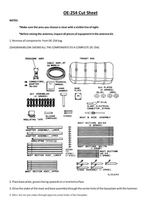
  • 1. OE-254 Cut Sheet NOTES: *Make sure the area you choose is clear with a visible line ofsight. *Before raising the antenna,inspect all piecesof equipmentinthe antenna kit. 1. Remove all components fromOE-254 bag. (DIAGRAMBELOW SHOWSALL THE COMPONENTSTO A COMPLETE OE-254) 2. Place base plate,grovesfacingupwardsona leveledsurface. 3. Drive the stake of the mast and base assemblythroughthe centerhole of the baseplate withthe hammer. 4. Drive the two pin stakes through opposite corner holes of the baseplate.
  • 2. 5. Locate the position of the four guy stake assemblies at a maximum radius of 25 feet from the center of the baseplate and a 90 degree angle between stakes. 6. Drive the four stakes at a 60-degree angle into the ground surface facing away from the mast. (FIGURE 2 SHOWS AN AREIAL IMAGE OF YOUR STAKE POSITIONING) 7. Assemble five lower mast sections by inserting the male ends into the female ends. 8. Place the bottomsection of the assembly over the movable portion of the mast and base assembly. 9. Slide a guy plate, color coded blue, onto the male end of the lower adapter assembly. 10. Assemble the lower adapter assembly to the five lower mast sections. 11. Assemble five upper mast sections and join them with the six already assembled. 12. Slide a guy plate, color coded red, onto the male end of the upper adapter assembly. 13. Assemble the upperadapter assembly to the mast. 14. Turn each guy plate so that one hole is uppermost. 15. Attach the guy hooks,color coded blue, of the four lower guy ropes to the holes of the lower guy plate. (FIGURE 3 IS A GRAPHIC DIAGRAM ON WHERE YOU SHOULD BE IN THE PROCESS) 16. Extend the guy ropes to the anchorassemblies 17. Attach the free guy loop of the guy snubberto the anchor hooks. * When attached this way, each guy rope can be pulled as taut as desired by lengthening the guy loop. 18. Attach the upperfour guys,color coded red, to the red guy plate and anchor assemblies in a similar manner. 19. Pull the four side guy ropes, two upper and two lower, make sure the cables are tight then secure them. * MAKE SURE THERE IS NO SLACK IN YOUR CABLE TO INCREASE SUPPORT AND STABILITY. 20. Acquire your feedcone assembly 21. Screw the insulating extension into the feedcone structure and assemble to the mast. (FIGURE 4 BELOW IS THE STEP YOUR CURRENTLY ON) 22. Assemble the, antenna elements by screwing Mast Sections AB- 24, MS-117A, and MS-116A. *ONLY 1 OF EACH ANTENNA ELEMENT SHOULD BE USED FOR 1 COMPLETE ANTENNA. 23. Attach the antenna elements to the feed cone assembly by screwing the male ends on MS-116A into the female sockets located on feed cone assembly.
  • 3. 24. Install antenna tips on each of the antenna elements and secure by wrapping with electrical tape if available. 25. Locate the point on the upper pulling guy rope where it meets the guy stake. * The lower pulling guy should be approximately one foot shorter than the upper pulling guy. 26. Tie a slip knot with the upperand lower pulling guys at that point and return to the base with the knot in hand. 27. Grasp the slip knot firmly in both hands pull the mast off the ground. * If available, raise the mast head off the ground up to four feet by using some kind of support box, or concrete block. 28. Walk backwards to the rear guy stake until the mast is fully erect. * Do not pull the lower pulling guy because it will automatically tighten during the lift up. *NOW IT’S TIME TO SET UP YOUR RADIO 29. If your MT-6352 VRC (your mounting base)is mounted inside of a vehicle your power cable should already be hooked up to yourJ1 power in connector. 30. Grab your radio mount bracket and slide it into the base plate. Make sure that all the connectors in the back of the mount are aligned, and secure the mount with the safety lock handle located at the mount of the mount. 31. Then depending on how may radios you are using,slide each 1523-E/F radio into its designated slot. *Only if using one radio slide it into the bottomsection of the mount know as alpha slot due to its long range capabilities. 32. Take the antenna cable from OE-254 and connect it to the J1 port on the AN-7238 (AMP) 33. Then connect yourW2 cable to your J2 port and turn the power on. YOU HAVE NOW COMPLETED THE RADIO CONNECTION PART. NOW IT’S TIME TO START THE RETRANS PORTION. BEFORE YOU START THIS PROCESS WHAT YOU NEED TO FIND OUT IS IF YOUR RETRANSMISSION IS TRADITIONAL OR SAME NET. THE DIFFERENCE BETWEEN BOTH IS TRADITION RETANSMISSION CONSIST OF 2 DIFFERENT SINGLE CHANNEL (SC) FREQUENCIES OR FREQUENCY HOPPING (FH) NET IDS COMMUNICATING WITH EACH OTHER. WHILE SAME NET RETRANSMISSION STATION CONSISTS OF ONE FREQUENCY HOPPING (FH) NET ID BEING RELAYED THROUGH THE SYSTEM TRADITIONAL RETRANSMISSION SETUP SAME NET RETRANSMISSION SETUP - PROGRAM THE RT-1523’S ACCORDING TO YOUR FREQUENCY PLAN - ESTABLISH COMMUNICATIONS WITH BOTH ENDS BEFORE INITIATING RETRANS MODE. - CONNECT THE RT-1523’S AT THE AUD/DATA PORT (RXMT) USING THE CX-13298 RXMT CABLE AND ROTATE THE RT-1523 FUNCTION KNOB TO RXMT. - LOAD THE RT-1523’S WITH COMSEC, INPUT THE NET ID, JULIANDATE, AND TIME. - ESTABLISH COMMUNICATIONS WITH BOTH ENDS BEFORE INITIATING RETRANS - CONNECT THE RT-1523’S AT THE AUD/DATA PORT (RXMT) USING THE CX-13298 RXMT CABLE AND ROTATE THE RT-1523 FUNCTION KNOB TO RXMT. - PRESS THE DATA (NUMBER 4 ON THE NUMBER PAD) BUTTON AND THEN THE CHANGE (CHG) BUTTON (NUMBER 7 ON THE NUMBER PAD) UNTIL ESIP RXMT PX OR TX IS DISPLAYED IN THE SCREEN OF THE RECEIVING RT-1523 - ONE RADIO WILL BE SET TO ESIP RXMT PX ANDTHE OTHER RADIOWILL BE SET TO ESIP RXMT TX *ONCE ALL OF THIS IS COMPLETED CHECK AND VERIFY THAT ALL CABLES ARE SECURE AND TIGHTENED. **YOU ARE NOW FULLY MISSION CAPABLE!