Reforço de armaduras de betão armado anti punçoamento
•
0 likes•1,113 views

El peso de una losa de hormigón soportado por una columna genera una tensión de esfuerzo cortante en la propia losa. Si este esfuerzo es suficiente y no se ha previsto un refuerzo adicional, puede hacer que la columna vaya “penetrando” en la losa. Este mismo esfuerzo cortante de penetración se produce en la base sobre la que descansa la columna. Aunque es posible liberar el esfuerzo cortante de penetración reforzando el hormigón en puntos localizados, ya sea con vigas de sujeción o ampliando la cabecera de las columnas, la construcción de losas planas ofrece múltiples ventajas. Un espacio de cabecera consistente puede reducir la altura general de un edificio y suponer un ahorro importante de tiempo y material.

Recommended
Recommended
More Related Content
What's hot
What's hot (20)
Similar to Reforço de armaduras de betão armado anti punçoamento
Similar to Reforço de armaduras de betão armado anti punçoamento (20)
More from CORTARTEC
More from CORTARTEC (11)
Recently uploaded
Recently uploaded (20)
Reforço de armaduras de betão armado anti punçoamento
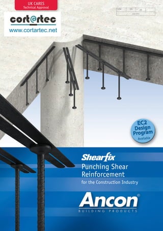
- 1. UK CARES Technical Approval CI/SfB (29) June 2012 Punching Shear Reinforcement for the Construction Industry Et6
- 2. Shearfix Punching Shear Reinforcement The weight of a slab supported on a column induces shear stresses in the slab. These stresses, if sufficient and where additional reinforcement has not been provided, would result in the column ‘punching’ through the slab. This punching shear is similarly induced in the footing on which the column bears. Although punching shear can be relieved by localised thickening of the concrete with downstand beams and enlarged column heads, the construction of flat slabs offers many advantages. A consistent head space can reduce the overall height of a building and provide significant time and material savings. Used within a slab to provide additional reinforcement around columns, Ancon Shearfix is the ideal solution to the design and construction problems associated with punching shear. The system consists of doubleheaded studs welded to flat rails, positioned around the column head or base. The shear load from the slab is transferred through the studs into the column. Contents Ancon Shearfix Design Sheet Comparison with Shear Links 4 Typical Rail Arrangements 10 System Components 5 Installation Procedure 10 Design Information: BS EN 1992-1-1:2004 Applications 11 6 Other Ancon Products 11 Design Program 7 Design and Technical Support 2 4 8 Tel: +44 (0) 114 275 5224 www.ancon.co.uk 9
- 3. Established, trusted name in concrete reinforcement Technical Approval TA7-5041 Free EC2 design program & technical support In-house manufacture from CARES-approved B500C rebar Full material traceability In-house, traceable batch testing Rounded rail ends for safer handling ISO 9001, ISO 14001 & OHSAS 18001 3
- 4. Shearfix Punching Shear Reinforcement Ancon Shearfix Used within a slab to provide additional reinforcement around columns, Ancon Shearfix is the ideal solution to the design and construction problems associated with punching shear. The system consists of double-headed studs welded to flat rails, positioned around the column head or base. The shear load from the slab is transferred through the studs into the column. Shearfix is suitable for all column shapes and is easy to install either ‘top down’ or ‘bottom up’, depending on user preference. Technical Approval Shearfix has been evaluated by UK CARES for use in reinforced concrete slabs and footings designed in accordance with BS EN 1992 (Eurocode 2). Although British Standard BS 8110 has now been withdrawn, shear reinforcement can be safely designed and detailed to EC2 where a structure, including the flexural reinforcement of its floor slabs, has been designed to this previous design code. Comparison with Shear Links Ancon Shearfix offers many advantages over loose shear links. Links can be timeconsuming to both design and install. A Shearfix system is easily detailed with Ancon’s free calculation program which generates a layout drawing for inclusion in the building plans and, rather than being installed individually, these studs are supplied to site welded to rails at the appropriate spacing. When comparing links with studs, research has shown that any additional material costs incurred when purchasing a prefabricated stud system, such as Shearfix, are generally far outweighed by the savings from a significantly reduced fixing time; these systems being up to ten times quicker to install (source: British Cement Association: Prefabricated punching shear reinforcement for reinforced concrete flat slabs. BCA, Camberley, 2001). Details for Specifying/Ordering Shearfix systems are designed to suit the specific load conditions at individual columns and are therefore manufactured to order. To specify and order an Ancon Shearfix system, download the free design program at www.ancon.co.uk or contact Ancon for technical support. Project Management Please contact Ancon if you would like help in creating a Shearfix schedule and a programme for delivery to suit progress on site. If advised at the time of ordering, pallets can be packed in priority order e.g by pour number. Corner column 4 Ancon’s ‘Products for Structural Concrete’ division offers a dedicated service to the concrete sector. Contact the team on +44 (0) 114 275 5224 with your Shearfix enquiry.
- 5. System Components Rail The Ancon Shearfix system comprises double-headed studs welded to flat rails. It is manufactured to suit the specific requirements of each application. The quantity of each component, the dimensions and spacings, and the layout pattern around the column are determined by calculation. Ancon provides free software to determine the optimum system design (see pages 6-7). Shearfix Studs Studs are manufactured in five diameters (10, 12, 16, 20 and 25mm) from CARES-approved B500C reinforcing bar. The heads are hot forged to three times the diameter of the bar. Studs are manufactured in virtually any length to suit the depth of slab, but are normally formed in increments of 5mm within the 1001000mm range. The bar used in this system has a characteristic yield strength of 500N/mm2. The first and last stud from each production batch is tested in-house to ensure the correct mechanical properties are maintained. Shearfix Rails The studs are welded to the rail at the centres determined by Ancon’s software or a design calculation. The rail performs no structural function but ensures stud alignment and positioning within the slab. Shearfix rails are manufactured from strips of steel which are 16mm wide x 3mm thick on studs up to 16mm in diameter and 20mm x 5mm on the larger two stud diameters. The rails feature rounded ends to reduce the risk of injury during handling. The gap between the strips allows for the passage of concrete during pouring and also enables the rail to be nailed through spacers to formwork when fixed ‘bottom up’ i.e. prior to all other reinforcement. Orthogonal Layout Double-headed Stud 10, 12, 16, 20 and 25mm diameters Radial Layout Product Identification Each rail of studs carries an identification code generated by the Ancon design program. To ensure the products and documentation can be cross-checked, these 16 digit reference codes are used throughout the process from design to installation. They appear on the calculation summary sheet, the DXF layout file and on each physical rail when delivered to site. Rails also include other references such as column number or floor level if provided at the time of ordering. ‘Top down’ installation. Rail is tied to the main reinforcement Spacer Bars (Optional) Spacer bars should be used with ‘top down’ fixing of an orthogonal rail layout, when rails run parallel to T1 reinforcement. The spacer bars are tied to the main T2 reinforcement where it is necessary to raise the level of the studs as if placed on T1 bars. 5
- 6. Shearfix Punching Shear Reinforcement Design Information: BS EN 1992-1-1:2004 The design of punching shear reinforcement should be carried out in accordance with the recommendations contained in BS EN 1992-1-1:2004. Shearfix designed to BS EN 1992 can also be applied to structures designed to BS 8110. The shear stress in the concrete is calculated at the column face and at the basic control perimeter (2d from the column face) to determine whether punching shear reinforcement is required. 2. 0d u1 ≤1 .5 d ≤ If reinforcement is required, the position of the outer control perimeter at which shear reinforcement is no longer needed (uout) is then calculated. Studs are arranged to start between 0.3d to 0.5d from the column face to within 1.5d of the outer control perimeter (uout); intermediate studs are positioned at 0.75d centres. The Ancon software defaults to a stud start point of 0.5d, although 0.3d is available as an option. Uout 1.5d max 0.3-0.5d u0 2.0d 0.75d 0.75d 0.75d A radial layout will normally provide the most cost-effective solution and rails can be arranged with either 30º or 45º between them. The tangential spacing between studs is kept to within 1.5d for studs within the basic control perimeter (u1) and 2d for studs outside the basic control perimeter; additional secondary rails are added as necessary to comply with this requirement. For internal, edge and corner columns where lateral stability does not depend on frame action between slabs and columns, and where adjacent spans differ by less than 25%, the recommended β values from BS EN 1992 can be applied to the design shear load VEd. Internal columns can also have moments applied in two directions in which case the β value is calculated, but for all other cases and for all re-entrant corner columns the design effective shear stress Veff should be entered which must include a value for β calculated in accordance with the guidance within BS EN 1992. Ineffective shear perimeter Openings in the slab Where there are openings in the slab within 6d of the column face a section of the slab will be ineffective and the perimeter lengths will be reduced. A series of rectangular openings can be added around each column using the Ancon design program which then calculates the required punching shear reinforcement. Opening Design Manual An Ancon Shearfix manual to EC2 is available. Contact Ancon for a copy. Any opening within 6d of column face must be considered U0 U1 2.0d Uout Face of loaded area = 0.3d to 0.5d 0.75d max. 0.75d max. 0.75d max. = 0.3d to 0.5d d Stud length Stud diameter Bottom cover 6 1.5d max. Top reinforcement Slab depth Top cover
- 7. Design Program Shearfix is designed to suit the specific requirements of each application. Ancon provides a free design program to simplify the specification and ordering of a Shearfix system. This easy-to-use program allows the optimum system design to be determined and generates a printable data sheet and a DXF file of the specified layout. Solutions can be created for all column sizes, shapes and locations including columns offset from edges and corners. Screen shot of a circular column offset from one edge, with a radial stud layout The program allows analysis to BS EN 1992 (Eurocode 2), BS 8110-1 and AS 3600. Where there are openings close to the column, a section of the slab will be ineffective and perimeters will need to be reduced; the Ancon design program allows these reductions to be applied to each perimeter. The program requires the following information: • Column shape (circular, rectangular or ‘L’ shape) • • Column dimensions • Dimension to concrete edge (for offset corner and edge columns) • • • • • • Slab thickness The DXF file generated The datasheet generated Column location (interior, edge, external corner, re-entrant corner) Concrete grade Reinforcement size and spacing Cover to reinforcement Shear load Applied moments This free program can be downloaded from www.ancon.co.uk or emailed on request. Contact Ancon on +44 (0) 114 275 5224 or info@ancon.co.uk. Technical Alliance with Bentley Systems In addition to the Ancon design program, the Shearfix design method has been integrated into RAM Concept, the market leading modelling tool for reinforced and posttensioned concrete floor slabs supplied by Bentley Systems. An alliance between Ancon and Bentley means users of RAM Concept can perform an automated punching shear analysis and detail shear stud rails in their building models. This enhanced functionality saves precious time at the design stage. Screen shot of a rectangular column at a re-entrant corner, with a radial stud layout The datasheet generated The DXF file generated 7
- 8. Shearfix Punching Shear Reinforcement Design and Technical Support In addition to the Shearfix design program shown on page 7, Ancon’s Technical Services Team offers free design and technical support. A design sheet is available which allows engineers to summarise the critical details of their project and request technical assistance with a Shearfix design. This form is shown on page 9. Guidance for Completion of BS EN 1992 (EC2) Design Sheet To ensure we receive all necessary design information Ancon requires the design information for each column to be compiled together. Unfortunately we are unable to offer a Shearfix design service based upon sets of separate drawings; the design sheet on the following page has been developed for the transfer of this information. Following receipt of the design information for each application you would like us to consider, calculation sheets will be returned to you detailing the required Shearfix rails. Loads Please note, that whilst there is a column on the design sheet for moments, these cannot be used in all applications. For different column types the following options are avaliable for specifying loads: Column Type Load Specification Options for EC2 Interior Specify VEd and Moments or Specify VEd with set factor of 1.15 or Specify Veff - Specify VEd with set factor of 1.4 or Specify Veff Corner - Specify VEd with set factor of 1.5 or Specify Veff Re-entrant Corner - - or Specify Veff N N z Mz Reinforcement in direction z Edge My z y z y z y z y Reinforcement in direction y Rail Arrangements Ancon provides solutions in either orthogonal or radial layouts, therefore please remember to indicate your preference on the design sheet. In the absence of this information we will provide what we consider to be the best i.e. most economical solution for each case which will inevitably mean a mix of the two in the overall design. Reinforcement Please indicate the reinforcement diameter and spacing on the sheet. Where additional reinforcement is being used, please provide both sizes i.e. for main reinforcement of Ø16mm @ 200mm spacings plus additional reinforcement of Ø20mm @ 200mm spacings, please write 16 + 20 @ 200. Edge Distances Edge distances are restricted to three times the effective depth where the effective depth is: slab depth - top cover - ( T1 + T2 ) 2 8
- 9. Rail Layout (tick one) . . . . . . . . . mm Moments** kNm Mz My Concrete cover bottom VEd (kN) Ultimate Load ULS Column Type (A1, A2...) (see below) Column Dimension (mm) yxz Edge Distance (mm) d* c* y A1 z Column Type edge y A2 d* z y A3 c* z edge d* d* z edge y A4 c* edge y A5 edge y A6 d* d* edge y A7 c* y A8 Orthogonal Page 1 of____ c* edge d* z vy void Void Position and Size y vz Voids (mm) Reinforcement (Please supply drawings in direction to clarify positions of voids) z Size Position bar Ø spacing vy vz y z * Maximum 3 x effective depth. ** Mz moments act in the columns y direction i.e. horizontally across the columns when orientated as shown below. Please refer to page 8 for more information. If left blank, standard factors will be applied. Your Column Reference Note: Refer to page 8 for information on moments and possible load combinations. Concrete strength C . . . . . . /. . . . . . . Veff (kN) Effective Load ULS . . . . . . . . . mm Concrete cover top Slab depth Reinforcement in direction y bar Ø spacing Email . . . . . . . . . . . . . . . . . . . . . . . . . . . . . . . . . . . . . . . . . . . . . . . . . . Date. . . . . . . . . . . . . . . . . . . . . . . . . . . . . . . . . . . . . . . . . . . . . . . . . . . OR Tel. . . . . . . . . . . . . . . . . . . . . . . . . . . . . . . . . . . . . . . . . . . . . . . . . . . . . ................................................. Best solution per column Radial Company . . . . . . . . . . . . . . . . . . . . . . . . . . . . . . . . . . . . . . . . . . . . . . . Project address.. . . . . . . . . . . . . . . . . . . . . . . . . . . . . . . . . . . . . . . . . . . . . . . . . . . . . . . . . mm Contact name . . . . . . . . . . . . . . . . . . . . . . . . . . . . . . . . . . . . . . . . . . . Project name . . . . . . . . . . . . . . . . . . . . . . . . . . . . . . . . . . . . . . . . . . . . Please refer to the additional guidance sheet before completing this form. Shearfix Punching Shear Reinforcement to BS EN 1992 (EC2) - Design Information edge
- 10. Shearfix Punching Shear Reinforcement Typical Rail Arrangements Shearfix is suitable for all column shapes and locations. Some typical arrangements are shown here. Radial Layouts Orthogonal Layouts Installation Procedure Ancon Shearfix is quick and simple to install. It can be fitted either ‘top down’ (after all other reinforcement) or ‘bottom up’ (prior to other reinforcement). ‘Top down’ Fixing • Fix all main reinforcement in position • • ‘Top down’ fixing Place Shearfix rails around the column to the layout detailed on job drawings by passing the studs through the reinforcement grid and resting the carrier rails on the top layer of reinforcement. Use spacer bars where required in orthogonal layouts - see page 5 for details Tie rails with wire to main reinforcement and pour concrete ‘Bottom up’ Fixing • Tie rails with wire to concrete spacers in order to maintain cover • • Hammer nails through gap in rails to fix the system to formwork • 10 Place rail and spacer units around the column to the layout detailed on job drawings Fix main reinforcement in position and pour concrete taking care not to displace the studs ‘Bottom up’ fixing
- 11. Applications Other Ancon Products Reinforcing Bar Couplers The use of reinforcing bar couplers can provide significant advantages over lapped joints. Design and construction of the concrete can be simplified and the amount of reinforcement required can be reduced. The Ancon range includes parallel threaded, tapered threaded and mechanically bolted couplers. Photo: University of Derby Reinforcement Continuity Systems Reinforcement Continuity Systems are an increasingly popular means of maintaining continuity of reinforcement at construction joints in concrete. Ancon Eazistrip is approved by UK CARES and consists of pre-bent bars housed within a galvanised steel casing. Once installed, the protective cover is removed and the bars are straightened. Markeaton Street, Derby, UK Insulated Balcony Connections Ancon Isolan connectors join external concrete balconies to internal concrete floor slabs. Used to minimise cold bridging, they provide continuity to the thermal insulation. Standard systems, comprising rigid CFC-free polystyrene insulation and duplex stainless steel shear reinforcement, suit most depths of cantilever and simply supported balconies. Conventional reinforcing bars are used to provide the tension and compression reinforcement. Kings Dock Mill, Liverpool, UK Shear Load Connectors Ancon DSD and ESD Shear Load Connectors are used to transfer shear across expansion and contraction joints in concrete. They are more effective at transferring load and allowing movement to take place than standard dowels, and can be used to eliminate double columns at structural movement joints in buildings. Channel and Bolt Fixings Ancon offers a wide range of channels and bolts in order to fix stainless steel masonry support, restraints and windposts to structural frames. Cast-in channels and expansion bolts are used for fixing to the edges of concrete floors and beams. Special Fabrications Ancon designs and manufactures high integrity steel components for a wide range of industries including Civil Engineering, Building, Infrastructure, Water Treatment, Nuclear and Mining. Projects are supplied worldwide and range from small-scale residential developments to major infrastructure projects. Victoria Point, Melbourne, Australia 11
- 12. Masonry Support Systems Lintels Masonry Reinforcement Windposts and Parapet Posts Wall Ties and Restraint Fixings Channel and Bolt Fixings Tension and Compression Systems Insulated Balcony Connectors Shear Load Connectors Punching Shear Reinforcement Reinforcing Bar Couplers Reinforcement Continuity Systems Stainless Steel Fabrications Flooring and Formed Sections Refractory Fixings These products are available from: The construction applications and details provided in this literature are indicative only. In every case, project working details should be entrusted to appropriately qualified and experienced persons. Whilst every care has been exercised in the preparation of this document to ensure that any advice, recommendations or information is accurate, no liability or responsibility of any kind is accepted in respect of Ancon Building Products. With a policy of continuous product development Ancon Building Products reserves the right to modify product design and specification without due notice. © Ancon Building Products 2012 ISO 9001: 2008 FM 12226 ISO 14001: 2004 EMS 505377 OHSAS 18001: 2007 OHS 548992