Roof Drainage Design for 292 ft by 124 ft Pitch Roof
•
3 likes•1,429 views

This document convers the design of gutters and downspouts/downpipes for roof drainage. The design includes sizing of the gutters and downspouts. The rain data used is as per National Building Code of Canada, 2010.

Recommended
More Related Content
What's hot
What's hot (20)
Viewers also liked
Viewers also liked (20)
Similar to Roof Drainage Design for 292 ft by 124 ft Pitch Roof
Similar to Roof Drainage Design for 292 ft by 124 ft Pitch Roof (20)
Recently uploaded
Recently uploaded (20)
Roof Drainage Design for 292 ft by 124 ft Pitch Roof
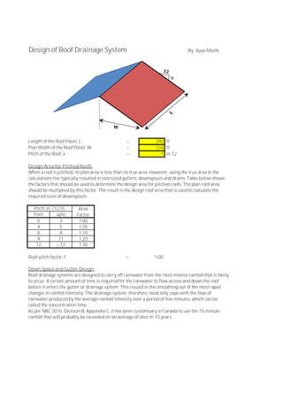
- 1. Design of Roof Drainage System By: Ayaz Malik Length of the Roof Panel, L = 292 ft Plan Width of the Roof Panel, W = 124 ft Pitch of the Roof, x = 1 in 12 Design Area for Pitched Roofs When a roof is pitched, its plan area is less than its true area. However, using the true area in the calculations has typically resulted in oversized gutters, downspouts and drains. Table below shows the factors that should be used to determine the design area for pitched roofs. The plan roof area should be multiplied by this factor. The result is the design roof area that is used to calculate the required sizes of downspouts. from upto 0 3 1.00 4 5 1.05 6 8 1.10 9 11 1.20 12 > 12 1.30 Roof-pitch factor, F = 1.00 Down Spout and Gutter Design Roof drainage systems are designed to carry off rainwater from the most intense rainfall that is likely to occur. A certain amount of time is required for the rainwater to flow across and down the roof before it enters the gutter or drainage system. This resulst in the smoothing out of the most rapid changes in rainfall intensity. The drainage system, therefore, need only cope with the flow of rainwater produced by the average rainfall intensity over a period of few minutes, which can be called the concentration time. As per NBC 2010, Division B, Appendix C, it has been customoary in Canada to use the 15-minute rainfall that will probably be exceeded on an average of once in 10 years. Area Factor Pitch, in. /12 in. x
- 2. Assumption: · Rainfall intensity is measured over a 15-minute period. It is recorded in mm/hour as the resulting accumulation, as if the intensity remained constant for a full hour. · It is assumed that during a rainfall with an intensity of 1 in. per hour, each in 2 of downspout can drain 1200 ft2 of roof. If the intensity is doubled, the downspout capacity is halved, or 600 ft 2 , if it is tripled the capacity is one-third, and so on. Downspout Design: Length of gutter per downspout = 40 ft (Note: each downspout should drain a maximum of 50 ft. of gutter) Plan Area of Roof, A = 4960 ft2 Roof Area to be drained, A x F = 4960 ft2 As per NBC 2010, Division B, Appendix C, Table C-2, for Fort McMurray, Rainfall intensity = 13.00 mm/15 min. = 52.00 mm/ hour = 2.05 in./hour For rainfall intensity of 2.05 in./hour, we have Area drained per in2 of downspout = 586.15 ft2 /in2 Required area of each downspout = 8.46 in2 (Governs) Minimum recommended area of each downspout = 7.00 in2 From the table provided in the end, we have following design choices: 1- 4 in. Dia. Plain Round 2- 4 in. Corrugated Round 3- 4 in. Plain Rectangular 4- 4 in. Corrugated Rectangular Gutter Design Ratio of Gutter depth to width, M = 0.50 Area to be drained, A = 4960.00 ft2 Rainfall intensity,I = 2.05 in./hour Length of the Gutter, L = 40 ft I x A = 10154 ft2 . in./hour In the chart provided in the end, find the vertical line representing L, proceed vertically along this line to its intersection with the oblique line representing M, then move horizontally to intersect the vertical line representing IA. The point of intersection gives the required width of the gutter. Width of the gutter (from chart) = 8 in. Depth of the gutter = 4 in.
- 4. Dimensions of Standard Downspouts